Product / HFS
Halton HFS – Reguleringsspjæld til statisk tryk
The static pressure control damper HFS is designed to be used in combination with static pressure measurement unit MSS to maintain the desired constant duct pressure.
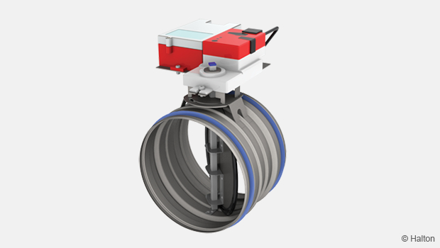
Overview
Terminated as of 1st December 2021
-> replaced with Halton Max One Circular (MOC)
- Til kanaltrykstyring
- Reguleringsspjældet til statisk tryk Halton HFS er designet til at blive brugt sammen med den statiske trykmålingsenhed Halton MSS for at opretholde det ønskede konstante tryk i kanalen.
- Automatisk slukkefunktion kan vælges, tæthed opfylder EN 1751, klasse 4 krav
- Klassificering af kabinettets tæthed: EN 1751, klasse C
- Cirkulær kanaltilslutning udstyret med integrerede gummipakninger
- Galvaniseret ståldesign
Modeller og tilbehør
- Model med forlænget aktuatorplatform til isoleringsarbejde på stedet.
- Model med fabriksmonteret isolering med eksternt metaldæksel
- Integreret luftstrømsmålingsenhed (manuel eller med 0…10 V outputsignal) som tilbehør
- Et udvalg af lyddæmpermodeller
Dimensioner og væg
Halton HFS/G, MU=NA

| NS | L | L1 | ØD |
| 200 | 145 | 70 | 199 |
| 250 | 145 | 70 | 249 |
| 315 | 145 | 70 | 314 |
| 400 | 245 | 175 | 399 |
| 500 | 245 | 175 | 499 |
HFS/E, MU=NA, model med forlænget aktuatorrække

| NS | L | L1 | ØD |
| 200 | 145 | 70 | 199 |
| 250 | 145 | 70 | 249 |
| 315 | 145 | 70 | 314 |
| 400 | 245 | 175 | 399 |
| 500 | 245 | 175 | 499 |
HFS/G, MU=A, model med manuel luftstrømsmåling

| NS | L | L1 | ØD |
| 200 | 470 | 398 | 199 |
| 250 | 470 | 398 | 249 |
| 315 | 470 | 398 | 314 |
| 400 | 625 | 553 | 399 |
| 500 | 625 | 553 | 499 |
HFS/G, MU=B, model med luftstrømsmålingsenhed (0…10 V)

| NS | L | L1 | ØD |
| 200 | 470 | 398 | 199 |
| 250 | 470 | 398 | 249 |
| 315 | 470 | 398 | 314 |
| 400 | 625 | 553 | 399 |
| 500 | 625 | 553 | 499 |
HFS/I, MU=A, isolering og manuel måling af luftstrøm

| NS | L | L1 | ØD |
| 200 | 465 | 393 | 199 |
| 250 | 465 | 393 | 249 |
| 315 | 465 | 393 | 314 |
| 400 | 675 | 603 | 399 |
| 500 | 675 | 603 | 499 |
HFS/I, MU= B, med isolering og luftstrømsmålingsenhed (0…10 V)

| NS | L | L1 | ØD |
| 200 | 465 | 393 | 199 |
| 250 | 465 | 393 | 249 |
| 315 | 465 | 393 | 314 |
| 400 | 675 | 603 | 399 |
| 500 | 675 | 603 | 499 |
Vægt
Halton HFS/G, MU=NA
| NS | kg |
| 200 | 2,36 |
| 250 | 2,74 |
| 315 | 3,35 |
| 400 | 4,58 |
| 500 | 6,14 |
Materialer
| Del | Materiale | Bemærking |
| Kabinet | Galvaniseret stål | |
| Dæmperblad | Galvaniseret stål | |
| Aksel | Forzinket stål | |
| Lejer | Plast | |
| Klingepakning | EPDM-gummi | |
| Kanalpakning | 1C-polyurethenblanding | |
| Måleprobe | Aluminium | |
| Udvendig isolering | Mineraluld | Model HFS/I |
| Ekstra beklædning | Galvaniseret stål | Model HFS/I |
Kanaltilslutningspakninger er vulkaniseret til beklædningen.
Funktion
Den statiske trykdæmper HFS opretholder det ønskede konstante kanaltryk, baseret på et statisk trykmålingssignal fra MSS-enheden (0…10 V).
Halton HFS funktioner
- Til forsynings- og udstødningsinstallationer
- Komplet nedlukningsfunktion
- Statisk tryk sat mellem 0…300 Pa (se MSS specifikationer).
- Maksimal trykforskel over dæmperen på 500 Pa
- Driftsområde: omgivelsestemperatur fra 0 til 50°C
- Relativ luftfugtighed < 95%, ikke-kondenserende
En optimal og stabil drift sikres ved hjælp af den statiske trykmålingsenhed Halton MSS. De angivne sikkerhedsafstande skal anvendes. Brug ikke andre trykmålingsenheder for at sikre korrekt kontrolnøjagtighed.
Halton MSS-enheden har flere trykmåleområder, 0…100 Pa, 0…200 Pa (standard), 0…500 Pa og 0…1000 Pa.
Luftstrømsmåling kan foretages manuelt ved hjælp af model HFS-A og manometer.
Med model Halton HFS-B er den faktiske luftstrømshastighed tilgængelig som 0…10 VDC eller 2…10 VDC-signal.
Halton HFS reguleringsspjældet indeholder en trykregulator (PC), der styrer spjældmotoren (FG) baseret på feedbacksignalet fra Halton MSS tryksenderen (PE), således at den indstillede værdi bliver realiseret.

Product Models
Halton HFS reguleringsspjæld til statisk tryk fås i flere forskellige versioner.
Klingepakningen giver lufttæt slukkefunktioner, og udvendig isolering bruges til at dæmpe udstrålet lyd ud i rummet og reducere varmeoverførslen. Isoleringsmodellen er dækket med et metalkabinet
| Model | Funktion | Tæthed |
| HFS/G, MU=NA | Statisk trykkontrol med klingepakning. | EN 1751, klasse 4 og C |
| HFS/E, MU=NA | Statisk trykkontrol med forlænget aktuatorplatform til isoleringsarbejde på stedet. | EN 1751, klasse 4 og C |
| HFS/G, MU=A | Statisk trykkontrol og manuel luftstrømsmålingsenhed med klingepakning. | EN 1751, klasse 4 og C |
| HFS/I, MU=A | Statisk trykkontrol og manuel luftstrømsmålingsenhed med klingepakning og 50 mm isolering. |
EN 1751, klasse 4 og C |
| HFS/G, MU= B | Statisk trykkontrol med luftstrømsmålingsenhed (udgangssignal 0…10 VDC) og klingepakning. |
EN 1751, klasse 4 og C |
| HFS/I, MU=B | Statisk trykkontrol med luftstrømsmålingsenhed (udgangssignal 0…10 VDC), klingepakning og 50 mm i isolering. |
EN 1751, klasse 4 og C |
Halton HFS reguleringsspjældet indeholder en trykregulator (PC), der styrer spjældmotoren (FG) baseret på feedbacksignalet fra Halton MSS tryksenderen (PE), således at den indstillede værdi bliver realiseret.

Trykreguleringsspjæld med manuel luftstrømsmåling

Trykreguleringsspjæld med luftstrømsmålingsenhed
Kontrolenhedt (CU)
Alle Halton HFS-modeller er udstyret med trykregulator Belimo VRP-STP og aktuator NM24A-V (CU=EP). Når modellen Halton HFS/S-D-B vælges, har Halton HFS en integreret luftstrømsmålingsenhed (MSD) og en analog signaltransmitter for målt luftstrøm.
Det indstillede punkt kan justeres lokalt med potentiometer eller via fjernstyring med 2-10 Vdc signal.
Se Halton MSS og Halton MSD teknisk data fra HIT-sektionen for de relevante data.
Sound Attenuators
SOUND ATTENUATORS (SA)
Sound attenuators are available with optional outlet diameters with mineral wool (MW) or polyester fibre (PEF) insulation materials and with 600 mm and 1000 mm lengths. Optionally the attenuator can be equipped with an access panel for cleaning and inspection purposes.
H1…H8 Attenuator without access panel
H11…H18 Attenuator with access panel
The connection (D1) is female type for direct connection to the HFS pressure control damper. The duct connection (D2) is male type and either damper size or one size larger. Technical information is based on bigger of the duct connections (D2).
| DIAMETER D1 |
MATERIAL | LENGTH mm |
ACCESS PANEL | |
| H1 | D1 = D2 | MW | 600 | No |
| H2 | D1 = D2 | MW | 1000 | No |
| H3 | D1 = D2 | PEF | 600 | No |
| H4 | D1 = D2 | PEF | 1000 | No |
| H5 | D1 | MW | 600 | No |
| H6 | D1 | MW | 1000 | No |
| H7 | D1 | PEF | 600 | No |
| H8 | D1 | PEF | 1000 | No |
| H11 | D1 = D2 | MW | 600 | Yes |
| H12 | D1 = D2 | MW | 1000 | Yes |
| H13 | D1 = D2 | PEF | 600 | Yes |
| H14 | D1 = D2 | PEF | 1000 | Yes |
| H15 | D1 | MW | 600 | Yes |
| H16 | D1 | MW | 1000 | Yes |
| H17 | D1 | PEF | 600 | Yes |
| H18 | D1 | PEF | 1000 | Yes |
Attenuator dimensions

The picture above describes supply air installation. In exhaust installation the airflow direction is vice versa, from D2 to D1.
| D1/D2 | D1/D2 | Nominal length |
L mm |
L2 mm |
W mm |
H mm |
MW Weight kg |
PEF Weight kg |
| 160/160 | 125/160 | 600 | 626 | 22 | 282 | 214 | 6.5 | 5.7 |
| 1000 | 1036 | 22 | 282 | 214 | 9.8 | 8.6 | ||
| 200/200 | 160/200 | 600 | 626 | 22 | 341 | 254 | 8.2 | 7.2 |
| 1000 | 1036 | 22 | 341 | 254 | 12.3 | 10.7 | ||
| 250/250 | 200/250 | 600 | 626 | 32 | 392 | 304 | 10.0 | 8.8 |
| 1000 | 1036 | 32 | 392 | 304 | 14.8 | 12.8 | ||
| 315/315 | 250/315 | 600 | 626 | 32 | 458 | 369 | 12.3 | 10.7 |
| 1000 | 1036 | 32 | 458 | 369 | 18.0 | 15.4 | ||
| 400/400 | 315/400 | 600 | 626 | 57 | 519 | 455 | 18.9 | 16.9 |
| 1000 | 1036 | 57 | 519 | 455 | 27.6 | 24.1 | ||
| 500/500 | 400/500 | 600 | 626 | 57 | 702 | 555 | 28.6 | 24.2 |
| 1000 | 1036 | 57 | 702 | 555 | 39.1 | 36.1 | ||
| 500/630 | 600 | 626 | 67 | 832 | 685 | 32.3 | 28.4 | |
| 1000 | 1036 | 67 | 832 | 685 | 50.3 | 43.8 |
Attenuation data
Material, Mineral wool (MW), frequency band (Hz)
| L = 600 | L = 1000 | |||||||||||||||
| D2 | 63 | 125 | 250 | 500 | 1k | 2k | 4k | 8k | 63 | 125 | 250 | 500 | 1k | 2k | 4k | 8k |
| 160 | 8 | 10 | 13 | 25 | 37 | 39 | 28 | 20 | 9 | 12 | 21 | 35 | 44 | 50 | 46 | 30 |
| 200 | 9 | 15 | 13 | 22 | 33 | 34 | 25 | 17 | 9 | 11 | 21 | 36 | 45 | 50 | 33 | 19 |
| 250 | 6 | 7 | 11 | 18 | 27 | 27 | 18 | 14 | 8 | 9 | 19 | 29 | 41 | 40 | 21 | 16 |
| 315 | 5 | 5 | 11 | 15 | 19 | 15 | 12 | 8 | 7 | 7 | 18 | 25 | 38 | 28 | 18 | 12 |
| 400 | 3 | 2 | 9 | 14 | 20 | 15 | 9 | 7 | 4 | 6 | 15 | 22 | 34 | 22 | 13 | 12 |
| 500 | 4 | 6 | 7 | 10 | 15 | 11 | 8 | 5 | 5 | 8 | 13 | 28 | 44 | 40 | 25 | 18 |
| 630 | 2 | 3 | 8 | 17 | 25 | 20 | 16 | 12 | 4 | 6 | 16 | 22 | 27 | 22 | 19 | 11 |
Material, Polyester fibre (PEF), frequency band (Hz)
| L = 600 | L = 1000 | |||||||||||||||
| D2 | 63 | 125 | 250 | 500 | 1k | 2k | 4k | 8k | 63 | 125 | 250 | 500 | 1k | 2k | 4k | 8k |
| 160 | 8 | 10 | 12 | 17 | 30 | 24 | 26 | 20 | 12 | 13 | 17 | 25 | 37 | 40 | 39 | 30 |
| 200 | 6 | 8 | 10 | 18 | 28 | 26 | 23 | 17 | 9 | 12 | 17 | 28 | 40 | 41 | 34 | 23 |
| 250 | 6 | 7 | 9 | 16 | 22 | 22 | 18 | 12 | 9 | 10 | 15 | 24 | 34 | 36 | 27 | 19 |
| 315 | 5 | 6 | 10 | 17 | 20 | 17 | 13 | 8 | 8 | 10 | 15 | 25 | 31 | 28 | 20 | 13 |
| 400 | 2 | 3 | 8 | 11 | 17 | 13 | 8 | 6 | 4 | 6 | 12 | 19 | 27 | 21 | 11 | 10 |
| 500 | 4 | 6 | 7 | 10 | 14 | 11 | 8 | 5 | 5 | 8 | 10 | 17 | 24 | 19 | 10 | 9 |
| 630 | 2 | 3 | 6 | 9 | 12 | 10 | 7 | 5 | 4 | 6 | 9 | 14 | 21 | 17 | 10 | 9 |
Installation
Safety distances
Install the unit into ductwork in such a way that the air flow direction through the unit is as indicated with the arrow in the unit casing.
The pressure control damper is installed taking into account the recommended safety distances for accurate and stable control.
Minimum safety distances of all HFS models

Bend T-branch; supply

T-branch; exhaust Sound attenuator
Static pressure measurement unit MSS should be installed in a ductwork in a place where static pressure is most suitable. Usually the place is in supply and exhaust duct 3/4 of ductwork length. Also safety distance before MSS unit must be observed.
Minimum safety distance between HFS and MSS

Supply air

Exhaust air
AIR FLOW MEASUREMENT WITH MSD
The pressure control damper with air flow measurement unit is installed taking into account the required safety distances. Install the unit into ductwork in such a way that the air flow direction through the unit is as indicated with the arrow in the unit casing.
Wiring
The wiring shall be carried out in accordance with local regulations and by professional technicians. For the power supply of all control options, a safety-isolating transformer shall be used.
Degree of protection
- Actuator NM24A-V: IP54
- Pressure controller VRP-STP: IP40
- Flow controller VRD3: IP40
The wiring instructions are presented for following applications:
1 A HFS; CU=EP Constant zone pressure control, set point adjusted locally
1 B HFS; CU=EP Constant zone pressure control, set point adjusted remotely
1 C HFS; CU=EP Overriding controls
2 A. HFS-B; CU=EP Constant zone pressure control with air flow measurement unit
Control unit
CU Description Note
EP Belimo VRD2 + NM24A-V 10 Nm
| MODEL | WIRE SIZING |
| HFS/x-NA, HFS/x-A | 8.1 VA |
| HFS/x-B | 11.6 VA |
1. HFS; CU=EP – duct pressure control

1.A. Typical duct pressure control local pressure set point.

1.B. Set point adjusted externally
1. HFS; CU=EP – duct pressure control with override controls
| OVERRIDE | A | B |
| CLOSED | Off | On |
| Pressure control |
Off | Off |
| OPEN | On | Off |

1.C. Duct pressure control with over-riding controls
CODE DESCRIPTION
Halton Delivered by Halton
3rd party Delivered by a third party
1 (^) 24 VAC system neutral
2 (~) 24 VAC live
3 (w1) 2…10 VDC pressure set point signal input when set point adjusted remotely
5 (U5) 2…10 VDC pressure feedback signal output
6 y Override input
7 z Override input
*) Jumper 2-4 factory-fitted for potentiometer set point; remove if 2…10-VDC input w1 is used
**) Diode 1N 4007
2. HFS-B; CU=EP – duct pressure control with air flow measurement unit

2.A. Duct pressure control with air flow measurement
CODE DESCRIPTION
Halton Delivered by Halton
3rd party Delivered by a third party
VRP-STP pressure controller
1 (^) 24 VAC system neutral
2 (~) 24 VAC live
3 (w1) 2…10 VDC pressure set point signal input when set point adjusted remotely
5 (U5) 2…10 VDC pressure feedback signal output
6 y Override input
7 z Override input
*) Jumper 2-4 factory-fitted for potentiometer set point; remove if 2…10-VDC input w1 is used
**) Diode 1N 4007
VRD3 air flow measurement
1 (^) 24 VAC system neutral
2 (~) 24 VAC live
5 (U5) 2…10 VDC pressure feedback signal output (actual airflow rate)
The output signal 5 (U5) can be used to control an eventual exhaust airflow control damper.
Pressure transmitter connection between HFS and MSS

Connector cable between HFS and MSS
Length of the cable for pressure measurement unit MSS provided with HFS is 0.7 m. Needed extension connection cable is supplied by 3rd party.
Code Wire
1 24 VAC system voltage
2 Neutral
3 0…10 VDC pressure measurement signal
Commissioning
Setting duct pressure
The pressure controller has a set point potentiometer for pressure set point adjustment.
Local setting
The pressure controller VRP-STP includes a potentiometer for static pressure set point adjustment (range: 30…100% of the selected MSS unit pressure range).
An example:
- Needed constant pressure set point is 120 Pa
- Choose pressure range of 0…200 Pa in MSS
- Adjust the set point potentiometer Dp% to 60% (=120 Pa / 200 Pa)
Remote setting
Set point can be set externally from building management system, air pressure range 0-100% corresponding to control signal range of 2-10 Vdc. Local set point potentiometer shall be set to 100%.
Defining measured duct pressure level
The actual measured static pressure level can be defined by the controller feedback signal (U5).
| SIGNAL | FORMULA | PRESSURE TRANSMITTER RANGE |
| 2…10 VDC | Pst = 100 Pa * (U5-2) / 8 | 100 Pa |
| Pst = 200 Pa * (U5-2) / 8 | 200 Pa | |
| Pst = 500 Pa * (U5-2) / 8 | 500 Pa | |
| Pst = 1000 Pa * (U5-2) / 8 | 1000 Pa |
The actual duct static pressure can also be read from the picture:

Static pressure and output signal
A = Pressure transmitter range 0…100 Pa
B = Pressure transmitter range 0…200 Pa

Static pressure and output signal
A = Pressure transmitter range 0…500 Pa
B = Pressure transmitter range 0…1000 Pa
Defining the measured airflow
With model HFS/ A air flow can be defined manually using integrated air flow measurement unit MSD.
Connect the measurement tubes to the manometer and read the pressure difference. The airflow rate is calculated using the formula below or by reading the airflow rate directly from the diagram.

K- factor
| D | k |
| 200 | 27.8 |
| 250 | 43.98 |
| 315 | 72.3 |
| 400 | 127.0 |
| 500 | 200 |
With model HFS/B air flow can be defined using integrated air flow measurement unit (MSD + VRD3). The actual measured airflow rate (qv) can be defined by the controller feedback signal (U5) and the nominal airflow (qv_nom) of the airflow measurement unit (VRD3).
| SIGNAL | FORMULA | CONTROLLER TYPE AND MODE |
TERMINALS SYSTEM NEUTRAL |
TERMINALS SIGNAL |
| 0…10 VDC | qv = qv_nom * U5 / 10 | HFS / B Mode 0 … 10 V |
1 (GND) | 5 (U5) |
| 2…10 VDC | qv = qv_nom * (U5 – 2) / 8 | HFS / B Mode 2 … 10 V |
1 (GND) | 5 (U5) |
Nominal airflow rates of the HFS are presented in the table below.
| NS | qv_nominal |
| 200 | 340 l/s (1226 m3/h) |
| 250 | 538 l/s (1936 m3/h) |
| 315 | 885 l/s (3188 m3/h) |
| 400 | 1555 l/s (5600 m3/h) |
| 500 | 2449 l/s (8818 m3/h) |
Specification
The static pressure control damper shall be made of galvanised steel. An additional airflow measurement probe is made of aluminium.
The tightness of the control damper in closed position shall conform to standard EN1751 class 4 and casing tightness to EN1751 class C.
Duct connection shall include integral airtight rubber gaskets.
The control damper section shall contain pressure controller and damper actuator and optionally airflow measurement. The damper shall be used in combination with MSS pressure measurement unit.
The damper shall be equipped with a sound attenuator in order to meet the sound level requirement for the room. As an optional extra, the sound attenuator shall have an access panel for cleaning purposes.
Product Code
HFS/S-D-MU
S = Construction
G Standard unit with blade gasket
E Standard unit with blade gasket and extended motor bed (for on-site insulation work)
I Unit with blade gasket and 50 mm insulation (only for models MU=A or MU=B)
D = Duct connection size
200, 250, 315, 400, 500
MU= Measurement unit
NA Not assigned
A Air flow measurement unit MSD (manual)
B Air flow measurement unit MSD+VRD3, electrical (0…10V)
Specifics and accessories
CU= Control unit
EP VRP-STP+NM24A-V
SA = Sound attenuator, connection sizes
NA Not assigned
H1 L = 600 mm; Outlet = inlet; Mineral wool
H2 L = 1000 mm; Outlet = inlet; Mineral wool
H3 L = 600 mm; Outlet = inlet; Polyester fiber
H4 L = 1000 mm; Outlet = inlet; Polyester fiber
H5 L = 600 mm; Outlet > Inlet; Mineral wool
H6 L = 1000 mm; Outlet > inlet; Mineral wool
H7 L = 600 mm; Outlet > inlet; Polyester fiber
H8 L = 1000 mm; Outlet > inlet; Polyester fiber
H11 L = 600 mm; Outlet = inlet; Mineral wool; Access panel
H12 L = 1000 mm; Outlet = inlet; Mineral wool; Access panel
H13 L = 600 mm; Outlet = inlet; Polyester fiber; Access panel
H14 L = 1000 mm; Outlet = inlet; Polyester fiber; Access panel
H15 L = 600 mm; Outlet > Inlet; Mineral wool; Access panel
H16 L = 1000 mm; Outlet > inlet; Mineral wool; Access panel
H17 L = 600 mm; Outlet > inlet; Polyester fiber; Access panel
H18 L = 1000 mm; Outlet > inlet; Polyester fiber; Access panel
Code example
HFS/G-200-B, CU=EP, SA=NA
Downloads
"*" indicates required fields