Product / CFD02
CFD-02TM 高温管道风闸
CFD-02TM高温管道风闸可直接用螺栓固定/夹紧在墙壁和地板上,或用螺栓固定在钢支撑框架/管道系统上。
概览
- 已成功测试能在400°C高温下运行2小时
- 经证明,在叶片关闭的情况下,该设计能够承受因压力瞬
变而产生的6000帕斯卡的重复荷载,达到780万次循环 - 风闸已根据UL555和BS476 PT20进行了2小时的耐火试验
- 叶片挠度测试在4000Pa, 400℃下持续1小时
- 100000次循环测试(自动运行)—— 耐久性测试
- 根据ASTM E2226 15b,在防火测试后进行UL风闸软管
流量测试 - 独立低需求SIL 4额定值
规格
Flamgard Calidair管道风闸设计严格,用于调节交通隧道中的气流。他们确保在隧道中流通的空气对旅客来说是安全的,不会产生过多废气。通常情况下,隧道风阀控制着隧道内的气体流量。
在紧急火灾情况下,重要的一点是,风闸不仅用于通风,而且用于控制火灾和相关的烟雾和热气。隧道火灾会产生严重的烟雾,如果没有可靠的通风,可能会导致隧道内人员因吸入烟雾而危及生命。 管道风闸可在紧急情况下使用,将这些有毒烟雾从关键区域排出,并在关闭时提供防火屏障。
高度定制的控制配置,实现最优的风阀有效截面,确保在紧凑现场条件下的最佳使用,改善空气流动,最大限度地减少压降。执行机构的位置也可以修改,以实现最佳的可进入性,便于调试和维护。
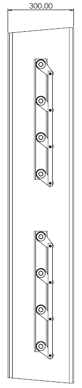
Dimensions
Casing
The damper casing is formed from 3.0 mm thick sheet steel into a rigid channel section to ensure proper alignment of blades and shafts. Damper units in excess of 2550mm width or 1900mm height shall be manufactured as a multiple assembly. Damper insertion depth is 300mm.
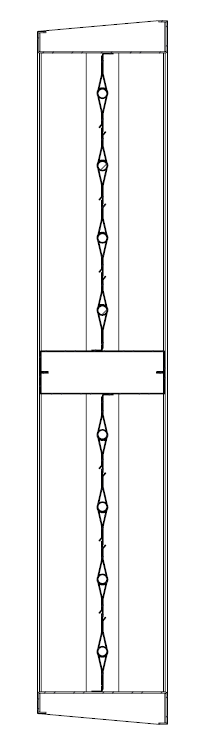
Blades
The blades are a formed double-skin aerofoil section of 2.0 mm sheet metal. Blade stops at the top and bottom of the casing and sprung side seals provide excellent low leakage characteristics. As an option, the blade ends can be capped and fitted with blade edge seals.
Shafts
Continuous shafts are Ø 20mm. The blades are plug welded at each end.
Linkage
Parallel action linkage consisting of drive levers connected by flat bar link bars, driven through stainless steel pins. All linkage is contained within the depth of the damper casing.
Bearings
Phosphor bronze self-lubricated ‘Oilite’ flanged bushes.
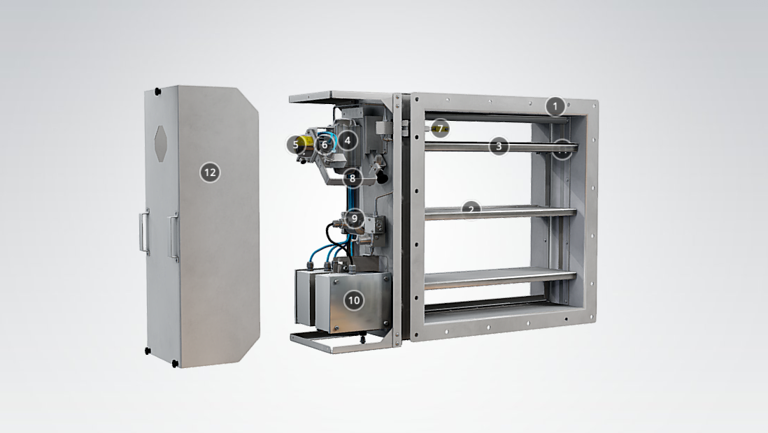
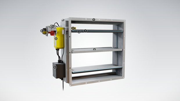
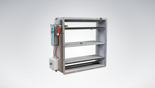
CFD-02TM General Drawings
Material and Finishing
| Part | Material | Finishing |
| Case | Mild Steel | Painted or Galvanised |
| Case | Stainless Steel – 1.4307 (304L) Stainless Steel – 1.4404 (316L) |
– |
| Blades | Mild Steel | Galvanised |
| Blades | Stainless Steel – 1.4307 (304L) Stainless Steel – 1.4404 (316L) |
– |
| Shafts | Stainless Steel – 1.4307 (304L) Stainless Steel – 1.4404 (316L) |
– |
| Bearings | Phosphor Bronze ‘Oilite’ (Self Lubricating) | – |
Product Models and Accessories
- Damper can be supplied with either a pneumatic or electric actuator depending on requirements
- The damper frame can be supplied with lifting eyes in each vertical side channel. These are provided for lifting the unit safely and without damage
- Actuators can be offset from the damper using a “pantograph” arrangement
- Thermal jacket can be supplied to protect the actuator from high a temperature environment.
Operation Principle
The CFD-02TM dampers utilize a parallel or opposed linkage system to open and close the damper units and can be normally open or normally closed depending upon the requirement. The airflow through the Flamgard Calidair damper is bi-directional and the orientation can be vertical or horizontal.
Weights
Weights for specific sizes are issued on the quotation documents.
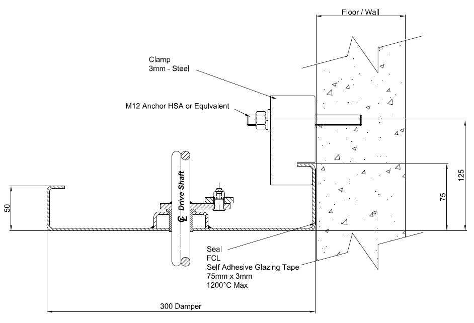
Installation
- Suitable clamps and wall anchors should be used to support the damper to the concrete surface.
- The wall anchors (bolts) and wall clamps are to be suitable to support the weight of the damper and for the mounting surface. They should also be suitable for the site conditions and location and design limits for high temperature applications. As a guide, wall clamps and anchors are to be at 200mm spacing around the damper mounting flange. The wall anchor bolts are to be installed as per manufacturers guidelines and set at the correct distance from the concrete opening.
- When mounting to a concrete surface, dampers cannot be ‘hung’ from the ceiling. For vertical or horizontal mounting to concrete surfaces.
- Gasket, suitable for the high temperature and leakage requirements, should be installed between the mounting surface and the damper to provide a seal.
- The joining plates to join modular dampers are supplied for direct mounting to the flanges of the damper. These can be sealed after damper assembly using suitable fire rated sealant to enhance the leakage performance.
- If the actuators are off-set from the damper, on a pantograph arrangement, an angle bracket is fitted to allow clamping of the pantograph to the wall/floor and to add support for the off-set weight of the actuator.
- The damper flanges are extended on each corner of damper assembly to provide a direct fixation of the damper at each corner to the wall. This provides additional support and also aids with installation.
Downloads
-
CFD-02TM – High temperature tunnel damper
Data
en
-
CFD -02TM – Korkean lämpötilan ilmavirtasäädin tunneliin
Data
fi
-
CFD-02TM – Registre de tunnel haute température
Data
fr
-
CFD-02TM – Tunnelklappe für hohe Temperaturen
Data
de
-
CFD-02TM 高温管道风闸
Data
cn
-
Halton-Flamgard CFD-02TM datasheet 2021
Data
English