Product / BDH
BDH 抗爆阀
Halton BDH 抗爆阀可以在海上、路上、重工业通风系统中防止超压。
概览
- 爆轰(冲击)型压力波冲击管试验
- 爆燃(爆炸)型压力波冲击管试验
- 冲击管测试符合GSA TS01和ASTM F 1642-04(2010)
- 碎片(钢球和木板条投掷物)冲击测试
- 碎片冲击试验符合ASTM E 1886-13a和ASTM E 1996-14a
- 根据EN 1751进行空气动力学测试
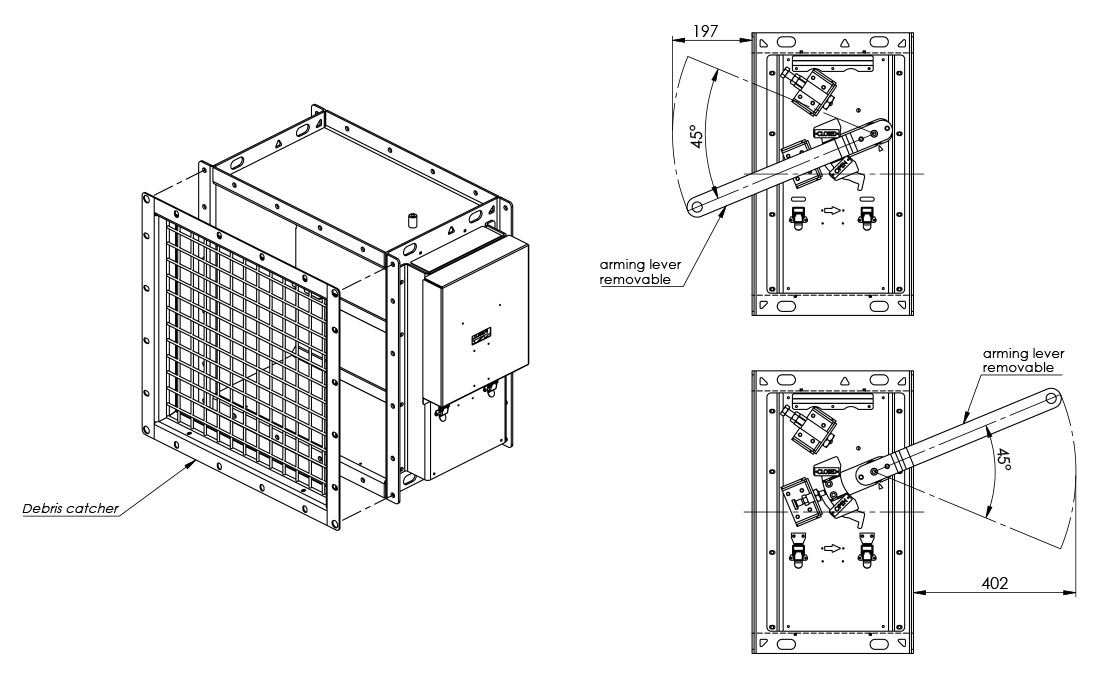
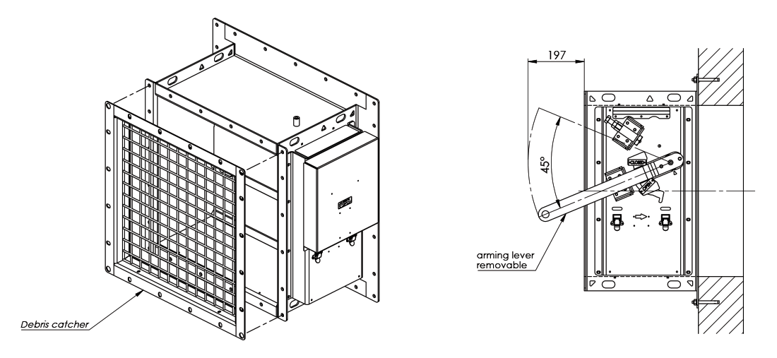
- 叶片角度的正常开启位置为45度
- 符合ATEX认证
- 建议最大风速为10 m/s
- 最大冲击波压力为1.0 bar
- 不锈钢抗爆阀的正常工作温度为 -60 ºC ~ +80 ºC
- 碳钢抗爆阀的正常工作温度为 -20 ºC ~ +80 ºC
规格
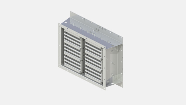
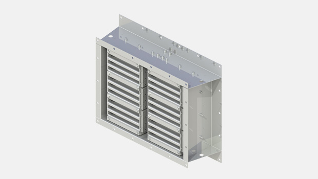
Halton BDH 抗爆阀可以在海上、路上、重工业通风系统中防止超压产生。BDH 抗爆阀可安装在矩形管道或墙壁开口中。当叶片处于开启位置时,该装置不会造成明显的压力损失、噪音或扰流。BDH有一个可调节的报警机制,以应对不同的风速和关闭压力要求。在抗爆阀外侧可以看到一个打开-关闭指示器。
不需要外部电源来运行抗爆阀。如果发生爆炸事件,压力波会关闭叶片。 有一个锁定机构,防止叶片在负相位打开。发生爆炸事件后,叶片保持锁定在关闭位置,直到重置(启用)抗爆阀。
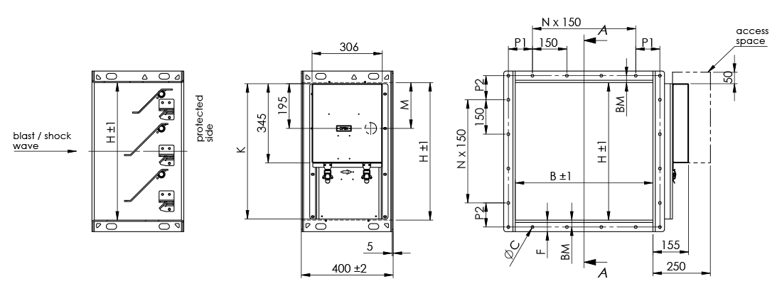
Dimensions and Material Thickness
BDH blast protection dampers are available for rectangular ducts and wall openings. Width B is 300-1200 mm, 25 mm division. Height H is 200-1200 mm, 50 mm division. Modular construction is available for larger sizes.
As a standard, flange width and bolt hole drilling are according to ISO 15138 standard.
Frame depth is 400 mm, frame thickness is 5 mm.
Blade thickness is 5 mm, blade shaft diameter is 25 mm. Blades are bolted to shafts.
The damper has 1-6 blades. In a multiblade damper (2-6 blades), blades are connected via linkage and operate in parallel. Linkage thickness is 8 mm.
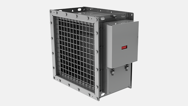
The debris catcher is a diameter of 6 mm wire. The open area between wires is 40 x 40 mm.
General BDH drawings
| H | M | K |
|---|---|---|
| 1200 | 200 | 1190 |
| 1150 | 200 | 1140 |
| 1100 | 200 | 1090 |
| 1050 | 200 | 1040 |
| 1000 | 200 | 990 |
| 950 | 200 | 940 |
| 900 | 200 | 890 |
| 850 | 200 | 840 |
| 800 | 200 | 790 |
| 750 | 200 | 740 |
| 700 | 200 | 690 |
| 650 | 200 | 640 |
| 600 | 200 | 590 |
| 550 | 200 | 540 |
| 500 | 200 | 490 |
| 450 | 250 | 440 |
| 400 | 200 | 435 |
| 350 | 200 | 435 |
| 300 | 50 | 440 |
| 250 | 50 | 435 |
| 200 | 50 | 435 |
| Damper size BxH | Opening size steel wall / duct coaming (max) BxH |
|---|---|
| 300×300 | 300×300 |
| 400×400 | 400×400 |
| 500×500 | 500×500 |
| 600×600 | 600×600 |
| 700×700 | 700×700 |
| 800×800 | 800×800 |
| 900×900 | 900×900 |
| 1000×1000 | 1000×1000 |
| 1100×1100 | 1100×1100 |
| 1200×1200 | 1200×1200 |
Flange dimensions according to ISO 15138
| DIMENSIONS | ØC | Bolt | P1, P2 | BM | F |
|---|---|---|---|---|---|
| If longest side < 350 | 10 | M8 | 75…150 | 20 | 40 |
| If longest side 351…1000 | 12 | M10 | 75…150 | 30 | 50 |
| If longest side > 1001 | 14 | M12 | 75…150 | 40 | 80 |
General BDH drawings for concrete wall
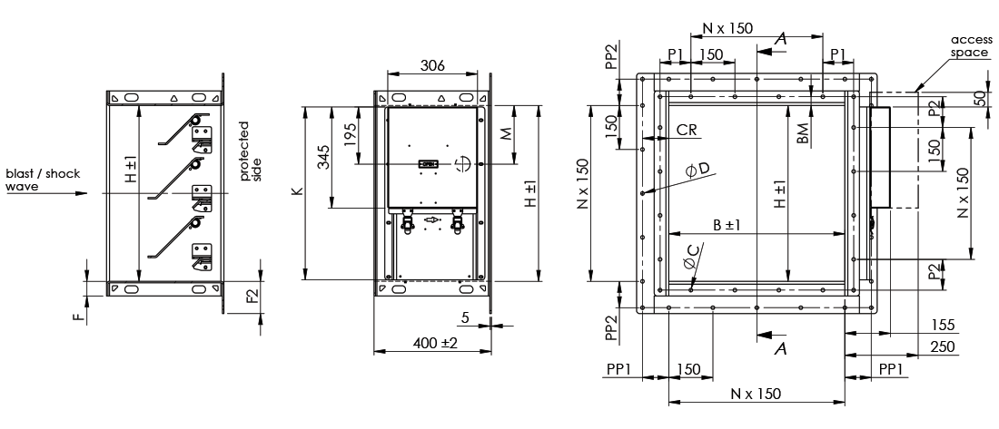
| H | M | K |
|---|---|---|
| 1200 | 200 | 1190 |
| 1150 | 200 | 1140 |
| 1100 | 200 | 1090 |
| 1050 | 200 | 1040 |
| 1000 | 200 | 990 |
| 950 | 200 | 940 |
| 900 | 200 | 890 |
| 850 | 200 | 840 |
| 800 | 200 | 790 |
| 750 | 200 | 740 |
| 700 | 200 | 690 |
| 650 | 200 | 640 |
| 600 | 200 | 590 |
| 550 | 200 | 540 |
| 500 | 200 | 490 |
| 450 | 250 | 440 |
| 400 | 200 | 435 |
| 350 | 200 | 435 |
| 300 | 50 | 440 |
| 250 | 50 | 435 |
| 200 | 50 | 435 |
| Damper size BxH | Opening size concrete wall BxH |
|---|---|
| 300×300 | 300×300 |
| 400×400 | 400×400 |
| 500×500 | 500×500 |
| 600×600 | 600×600 |
| 700×700 | 700×700 |
| 800×800 | 800×800 |
| 900×900 | 900×900 |
| 1000×1000 | 1000×1000 |
| 1100×1100 | 1100×1100 |
| 1200×1200 | 1200×1200 |
Flange dimensions according to ISO 15138
| DIMENSIONS | ØC | Bolt | P1, P2 | BM | F | P1, P2 | CR | F2 |
|---|---|---|---|---|---|---|---|---|
| If longest side < 350 | 10 | M8 | 75…150 | 20 | 40 | 75…150 | 75 | 95 |
| If longest side 351…1000 | 12 | M10 | 75…150 | 30 | 50 | 75…150 | 90 | 110 |
| If longest side > 1001 | 14 | M12 | 75…150 | 40 | 80 | 75…150 | 105 | 145 |
Material and Finishing
| PART | MATERIAL | FINISHING |
|---|---|---|
| Frame | Carbon steel | Painted or hot-dip galvanised |
| Frame | Stainless steel EN 1.4404 (AISI 316L) |
– |
| Blades | Carbon steel | Hot-dip galvanised |
| Blades | Stainless steel EN 1.4404 (AISI 316L) |
– |
| Setting, closing and locking mechanism | Stainless steel EN 1.4404 (AISI 316L) and some parts EN 1.4305 (AISI 303) or similar |
– |
| Maintenance-free bearings | Stainless steel EN 1.4404 (AISI 316L) |
– |
| Shafts | Stainless steel EN 1.4404 (AISI 316L) |
– |
| Debris catcher | Carbon steel | Hot-dip galvanised |
| Debris catcher | Stainless steel EN 1.4404 (AISI 316L) |
– |
Product Models and Accessories
Arming tool to open the damper, at least one tool per building.
Debris catcher to prevent large objects from entering the protected area.
Mesh finger guard for personnel safety to prevent touching armed blades. Can be installed on the protected side, exposed side or both.
Weights
Standard Halton Marine BDH dampers (kg)
| H / HEIGHT (mm) |
B / WIDTH (mm) | |||||||||
|---|---|---|---|---|---|---|---|---|---|---|
| 300 | 400 | 500 | 600 | 700 | 800 | 900 | 1000 | 1100 | 1200 | |
| 200 | 41 | 43 | 46 | 49 | 52 | 55 | 57 | 60 | 63 | 66 |
| 300 | 52 | 56 | 60 | 63 | 67 | 71 | 75 | 79 | 83 | 87 |
| 400 | 63 | 68 | 73 | 78 | 83 | 88 | 93 | 98 | 103 | 108 |
| 500 | 74 | 80 | 86 | 92 | 99 | 105 | 111 | 117 | 123 | 129 |
| 600 | 85 | 92 | 100 | 107 | 114 | 122 | 129 | 136 | 143 | 151 |
| 700 | 96 | 105 | 113 | 122 | 130 | 138 | 147 | 155 | 164 | 172 |
| 800 | 107 | 117 | 126 | 136 | 146 | 155 | 165 | 174 | 184 | 193 |
| 900 | 122 | 133 | 143 | 154 | 165 | 175 | 186 | 197 | 207 | 218 |
| 1000 | 133 | 145 | 157 | 168 | 180 | 192 | 204 | 216 | 227 | 239 |
| 1100 | 144 | 157 | 170 | 183 | 196 | 209 | 222 | 235 | 248 | 260 |
| 1200 | 155 | 169 | 183 | 197 | 211 | 226 | 240 | 254 | 268 | 282 |
Standard Halton Marine BDH dampers for concrete wall (kg)
| H / HEIGHT (mm) |
B / WIDTH (mm) | |||||||||
|---|---|---|---|---|---|---|---|---|---|---|
| 300 | 400 | 500 | 600 | 700 | 800 | 900 | 1000 | 1100 | 1200 | |
| 200 | 44 | 47 | 50 | 53 | 56 | 59 | 62 | 65 | 68 | 71 |
| 300 | 55 | 60 | 64 | 68 | 72 | 76 | 80 | 84 | 89 | 93 |
| 400 | 67 | 72 | 78 | 83 | 88 | 94 | 99 | 104 | 110 | 115 |
| 500 | 79 | 85 | 92 | 98 | 105 | 111 | 118 | 124 | 131 | 137 |
| 600 | 90 | 98 | 106 | 113 | 121 | 129 | 136 | 144 | 152 | 159 |
| 700 | 102 | 111 | 120 | 129 | 137 | 146 | 155 | 164 | 173 | 181 |
| 800 | 114 | 124 | 134 | 144 | 154 | 164 | 174 | 184 | 193 | 203 |
| 900 | 129 | 140 | 151 | 162 | 173 | 185 | 196 | 207 | 218 | 229 |
| 1000 | 141 | 153 | 165 | 177 | 190 | 202 | 214 | 227 | 239 | 251 |
| 1100 | 152 | 166 | 179 | 193 | 206 | 219 | 233 | 246 | 260 | 273 |
| 1200 | 164 | 179 | 193 | 208 | 222 | 237 | 252 | 266 | 281 | 295 |
Installation
The damper can be installed vertically outside of the building wall or between duct flanges. Also, horizontal installation is possible on the duct, floor or roof but only in the top-down blast direction.
The wall (or floor/roof) material can be concrete or steel.
For concrete wall installation, a wide-flange version is used and the damper is installed using anchor bolts.
For steel wall installation, the damper is installed using bolts or by welding.
Detailed installation information is available in the BDH installation, operation and maintenance manual.
Downloads
-
BDH – Blast protection damper
Data
en
-
BDH – Räjähdyspelti
Data
fi
-
BDH – Clapet anti-souffle
Data
fr
-
BDH – Explosionsschutzklappe
Data
de
-
BDH 抗爆阀
Data
cn
-
Halton BDH datasheet 2023
Data
English -
ATEX Certificate for Halton BDH
Data
English -
EAC Certificate for Halton FDA, FDB2, FDO, FDH, FCE, UTA, UTG, BDH, BRD, BLD
Data
Русский (ru)