Product / FDB2
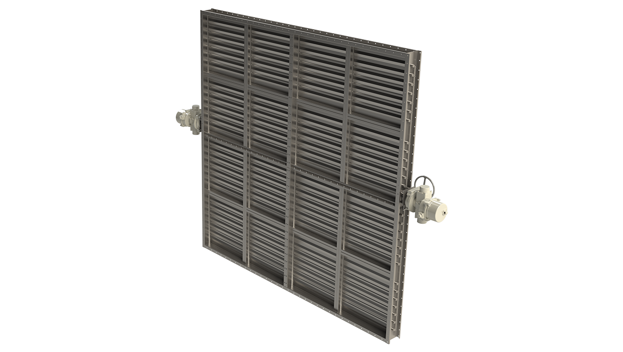
FDB2 用于高要求应用的 A0(A60) 防火隔烟阀
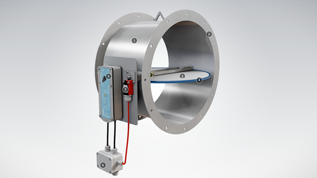
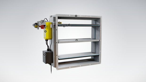
Halton FDB2 防火隔烟阀是世界上最畅销的船舶用防火隔烟阀。


概述
- 获得各类著名船级社的型式认可:A0 级无绝缘,A15-A60 适当绝缘
- 可进行 ATEX 认证。通过冲击测试。
- 风叶包含硅胶(温度可达 300 ºC),防止正常环境下泄漏,以及热膨胀石墨密封条(150 ºC 以上有效),
在起火状况下使风闸紧密度可增加 50%。闭合的阀符合防泄漏等级 3 的要求 (EN1751:1998)。测试尺寸为 1000×1000 mm。 - 标称熔断温度为 50 ºC、74 ºC 或 100 ºC。可选其它
温度。 - 专利双层风叶结构,重量轻巧
- 自动、气动或手动执行器可选
- 阀门结构可适应的最大管道压力为 5000 Pa,最大
空气流速为 15 m/s - 特定风闸可提供SIL 2安全认证
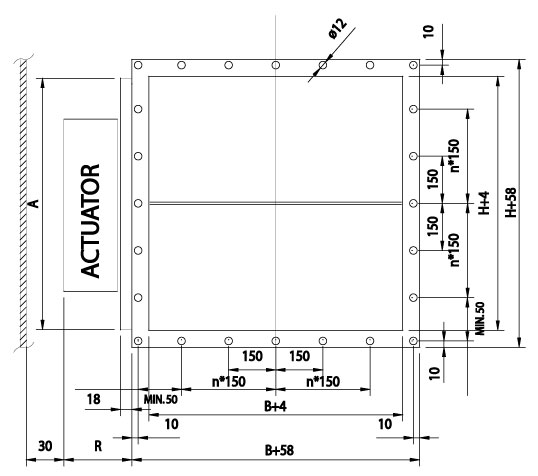
Dimensions
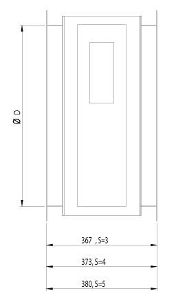
FDB2 fire dampers meet international standards for both rectangular (width B 100-1200 mm and height H 100-1600 mm, 1 mm division) and circular ducts (Ø100-1250 mm). Modular constructions are available for bigger sizes. Non-standard dimensions and flange drilling available on request. Standard flange width 27 mm. Flanges and drilling also available according to ISO 15138 standards. Frame thickness 3 mm or 3-5 mm according to SOLAS. Also 6, 8 and 10 mm frame thicknesses are available on request. Blades are made of two sheets, each of them being 1 mm thick (sandwich design).
Frame thickness according to SOLAS
| DIMENSIONS | S |
| If B or H > 100, but < 449 | 3 |
| If B or H > 450 but < 649 | 4 |
| If B or H > 650 | 5 |
Frame thickness according to SOLAS, Edition Dec. 2015
| DIMENSIONS | S |
| If A < 0.075 m2 | 3 |
| If A > 0.075 and A < 0.45 m2 | 4 |
| If A > 0.45 m2 | 5 |
Actuator effect in dimensions
| ACTUATOR | R | A | |
| Electrical (EL) | BF230, BF24, BF120 | 100 | H<300 = 300, H>300 =H |
| Pneumatic (PNR) | Pneumatic rotating actuator AT100 | 170 | H<300 = 300, H>300 =H |
| Pneumatic (PNR) | Pneumatic rotating actuator AT200 | 190 | H<350 = 350, H>350 =H |
| Spring (SP) | Spring | 140 | H |
The above table contains only some examples of actuators and their effect on dimensions.
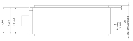
FDB2 general drawings
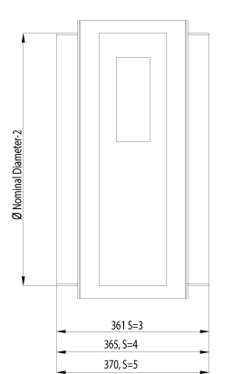
FDB2 circular connections
FDB2 general drawing, top
FDB2 general drawing, circular with connection flanges
| DAMPER HEIGHT | TOTAL DEPTH WITH BLADES OPEN |
| < 250 mm | 210 mm |
| > 250 mm < 300 mm | 250 mm |
| > 300 mm < 349 mm | 210 mm |
| > 350 mm | 240 mm |
Material and Finishing
| PART | MATERIAL | FINISHING |
| Frame | Carbon steel | Painted or galvanized |
| Frame | Stainless steel EN 1.4301 (AISI304), EN 1.4404 (AISI316L), EN 1.4432 (AISI316L) | – |
| Blades | Steel | Galvanized |
| Blades | Stainless steel EN 1.4301 (AISI304), EN 1.4404 (AISI316L), EN 1.4432 (AISI316L) | – |
| Maintenance-free bearings |
Stainless steel EN 1.4404 (AISI316L) | – |
| Shafts | Stainless steel EN 1.4404 (AISI316L) | – |
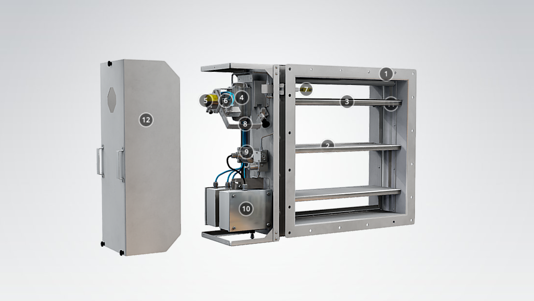
Product Models and Accessories
Halton FDB2 is available with following actuators:
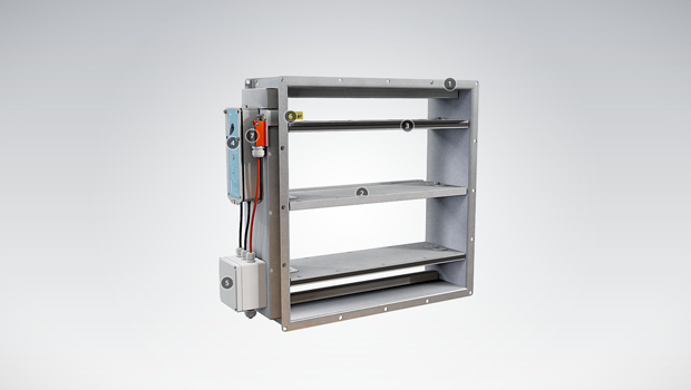
- FDB2-EL: Electrical spring return motor; standard actuators being 24 V or 230 V or 120 V. The motor contains built-in open-closed limit switches. Separate junction box included in the EL-model. A wide range of Ex actuators available, including a one second closing time function as an option.
- FDB2-PNR: Pneumatic rotating actuator
- FDB2-SP: Manual spring-actuated damper with fusible link
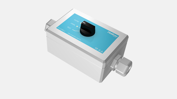
DOT: manual override function available for PNR and EL models.
HSO: Halton Smart Override function for HVAC damper black-start available for PNR and EL models. With automatic reset function when power and/or pneumatic air supply is reinstated.
A wide range of accessories available.
Operation Principle
In the event of a temperature rise in ductwork:
- FDB2-EL: fusible link releases and cuts off operating voltage to the spring return motor, allowing the spring to close the damper blades. The fire damper opens automatically when the fuse has been changed and the operating voltage to the motor is re-established.
- FDB2-PNR: fusible link releases and cuts off operating pressure to the spring return actuator, allowing springs to close the damper blades. The fire damper opens automatically when the fuse has been changed and the pneumatic air supply is re-established.
- FDB2-SP: fusible link releases allowing the spring to close the damper blades. When the fuse has been changed, the fire damper must be reset into open position manually.
Weights
Weights of standard Halton Marine FDB2 dampers without an actuator (kg)
| H/HEIGHT (mm) |
B / WIDTH (mm) | |||||||||||
| 100 | 200 | 300 | 400 | 500 | 600 | 700 | 800 | 900 | 1000 | 1100 | 1200 | |
| 100 | 5 (5) | 7(7) | 9(9) | 10(10) | 12(13) | 14(15) | 15(22) | 17(25) | 19(27) | 20(30) | 22(32) | 24(35) |
| 200 | 7(7) | 9(9) | 11(11) | 12(12) | 14(16) | 16(18) | 18(26) | 20(28) | 22(31) | 23(34) | 25(36) | 27(39) |
| 300 | 9(9) | 11(11) | 13(13) | 15(15) | 17(19) | 19(21) | 21(30) | 23(32) | 25(35) | 27(38) | 29(41) | 31(43) |
| 400 | 11(11) | 13(13) | 15(15) | 17(17) | 20(22) | 22(24) | 24(33) | 26(36) | 28(39) | 30(42) | 32(45) | 34(48) |
| 500 | 13(16) | 16(19) | 18(22) | 21(25) | 23(27) | 25(30) | 28(38) | 30(41) | 32(44) | 35(47) | 37(50) | 39(54) |
| 600 | 15(18) | 18(21) | 20(24) | 23(27) | 25(30) | 28(33) | 30(41) | 33(45) | 35(48) | 38(51) | 40(55) | 43(58) |
| 700 | 18(25) | 21(28) | 23(32) | 26(35) | 29(39) | 32(42) | 34(46) | 37(50) | 40(53) | 42(57) | 45(60) | 48(64) |
| 800 | 20(27) | 23(31) | 25(35) | 28(38) | 31(42) | 34(46) | 37(50) | 40(53) | 43(57) | 46(61) | 49(64) | 51(68) |
| 900 | 22(31) | 25(35) | 28(39) | 32(42) | 35(46) | 38(50) | 41(54) | 44(58) | 47(62) | 50(66) | 53(70) | 56(74) |
| 1000 | 24(33) | 27(37) | 31(41) | 34(45) | 37(50) | 40(54) | 44(58) | 47(62) | 50(66) | 53(70) | 57(74) | 60(78) |
| 1100 | 26(36) | 30(41) | 33(45) | 37(49) | 40(54) | 44(58) | 47(62) | 51(67) | 54(71) | 58(75) | 61(79) | 65(84) |
| 1200 | 28(39) | 32(44) | 36(48) | 39(52) | 43(57) | 46(61) | 50(66) | 54(70) | 57(75) | 61(79) | 65(84) | 68(88) |
| 1300 | 31(42) | 35(47) | 38(52) | 42(56) | 46(61) | 50(66) | 54(70) | 58(75) | 62(80) | 65(84) | 69(89) | 73(94) |
| 1400 | 32(45) | 37(50) | 41(55) | 45(59) | 49(64) | 53(69) | 57(74) | 61(79) | 65(84) | 69(88) | 73(93) | 77(98) |
| 1500 | 35(48) | 39(53) | 43(58) | 48(63) | 52(68) | 53(73) | 60(78) | 65(83) | 69(89) | 73(94) | 77(99) | 82(104) |
| 1600 | 36(51) | 41(56) | 45(61) | 50(66) | 54(72) | 59(77) | 63(82) | 67(87) | 72(92) | 76(98) | 81(103) | 85(108) |
| D2 ØD | WEIGHT |
| (mm) | kg |
| 100 | 8 (8) |
| 125 | 8 (8) |
| 160 | 12 (12) |
| 200 | 13 (13) |
| 250 | 19 (19) |
| 315 | 20 (20) |
| 400 | 27 (27) |
| 500 | 35 (43) |
| 630 | 46 (62) |
| 800 | 62 (89) |
| 1000 | 83 (118) |
| 1250 | 113 (162) |
(Frame thickness according to SOLAS)
Examples of actuator weights: FDB2-EL GGA 326.1E 2,3 kg, GNA 326.1E 1,3 kg, BF230 +3,2 kg, BLF230 +1,7 kg, ExMax/Redmax +3,5 kg, CSQP +3 kg ,
FDB2-PNR AT100 +2,1 kg, AT100 as AISI316 4,4 kg, AT200 +3,2kg, AT200 as AISI316 +6,2 kg, FDB2-SP +1 kg. Control enclosure +4 kg.
Installation
Installation and maintenance instructions are with each fire damper delivery. Copies of Operation and Maintenance manuals are available from Halton Marine Sales offices and distributors.
Product Code
| (S)=Shape of Connection | |||||||
| (A) Circular on one side | |||||||
| (C ) Circular on two sides | |||||||
| (R) Rectangular | |||||||
| (W)=Width | |||||||
| 100-1200 | |||||||
| (H)=Height | |||||||
| 100-1600 | |||||||
| (D)=Diameter | |||||||
| 100-1250 | |||||||
| (FA)=Fire Approval | |||||||
| (C1) ABS American Bureau of Shipping | |||||||
| (C2) MED Marine Equipment Directive | |||||||
| (C3) LRS Lloyds Register | |||||||
| (C4) DNV-GL | |||||||
| (C5) BV Bureau Veritas | |||||||
| (C9) RMRS Russian Maritime Register | |||||||
| (EX)=Atex Class | |||||||
| (NA) No | |||||||
| (X1) ATEX certified damper [please fill] | |||||||
| (SF)=Flange Option | |||||||
| (H0) Eurovent flange in circular connections | |||||||
| (H1) Eurovent flange + loose flange in circular connections | |||||||
| (HA) Eurovent flanges | |||||||
| (HB) Eurovent flanges + counter flanges (2 sides) | |||||||
| (HC) Eurovent flanges + counter flange (1 side) | |||||||
| (N0) ISO15138 flange drilling in circular connection | |||||||
| (N1) ISO15138 flange drilling + Loose flange in circular connection | |||||||
| (NA) Circular connections without flanges | |||||||
| (NR) ISO15138 flange drilling | |||||||
| (FS)=Frame Dimensioning | |||||||
| (HS) Manual dimensioning | |||||||
| (SO) SOLAS dimensioning | |||||||
| (S1) SOLAS dimensioning (supplement 2015) | |||||||
| (MA)=Material | |||||||
| (AS) Stainless steel 1 mm EN1.4404 | |||||||
| (CS) Carbon steel 1 mm | |||||||
| (LS) Stainless steel 1 mm EN1.4432 | |||||||
| (SS) Stainless steel 1 mm EN1.4301 | |||||||
| (FM)=Frame Material | |||||||
| (A3) Stainless steel 3 mm EN1.4404 | |||||||
| (A4) Stainless steel 4 mm EN1.4404 | |||||||
| (A5) Stainless steel 5 mm EN1.4404 | |||||||
| (C3) Carbon steel 3 mm | |||||||
| (C4) Carbon steel 4 mm | |||||||
| (C5) Carbon steel 5 mm | |||||||
| (L3) Stainless steel 3 mm EN1.4432 | |||||||
| (L4) Stainless steel 4 mm EN1.4432 | |||||||
| (L5) Stainless steel 5 mm EN1.4432 | |||||||
| (S3) Stainless steel 3 mm EN1.4301 | |||||||
| (S4) Stainless steel 4 mm EN1.4301 | |||||||
| (S5) Stainless steel 5 mm EN1.4301 | |||||||
| (FI)=Finishing | |||||||
| (HG) Hot galvanized | |||||||
| (NA) Acid treatment | |||||||
| (PN) Standard painting grey RAL7001 | |||||||
| (PX) Special Painting C5-M ISO12944 | |||||||
| (IN)=Insulation | |||||||
| (N) No | |||||||
| (Y) A60 insulation on actuator side | |||||||
| (RE)=Actuator | |||||||
| (E1) Electric – Belimo, BF24-2-HL | |||||||
| (E3) Electric – Belimo, BF230-2-HL | |||||||
| (E7) Electric – Belimo, BF120-HL | |||||||
| (E8) Electric – Belimo, NF24A-SR | |||||||
| (E9) Electric – Belimo, NF24A-SR-S2 | |||||||
| (E10) Electric – Belimo, SF24A-SR | |||||||
| (E11) Electric – Belimo, SF24A-SR-S2 | |||||||
| (I1) InMax – Schischek, 15-SF | |||||||
| (I2) InMax – Schischek, 15-SF VAS | |||||||
| (I3) InMax – Schischek, 15-SF1 VAS | |||||||
| (I4) InMax – Schischek, 8-SF-1 | |||||||
| (I6) InMax – Schischek, 15-SF-1 | |||||||
| (I9) InMax – Schischek, 5.10-SF | |||||||
| (I10) InMax – Schischek, 5.10-SF VAS | |||||||
| (I11) InMax – Schischek, 8-SF-1 VAS | |||||||
| (K0) Electric – Belimo, BFN24.1 | |||||||
| (K2) Electric – Belimo, BFN230.1 | |||||||
| (P0) Pneumatic – Air Torque, AT101, Aluminium | |||||||
| (P3) Pneumatic – Air Torque, AT104, AISI316 | |||||||
| (Q1) Pneumatic – Air Torque, AT201, Aluminium | |||||||
| (Q2) Pneumatic – Air Torque, AT204, AISI316 | |||||||
| (S1) Spring | |||||||
| (T1) Electric – Belimo, BF24-T-2.1HL | |||||||
| (T3) Electric – Belimo, BF230-T-2.1HL | |||||||
| (Z2) Electric (EX) – Schischek, ExMax 15-SF | |||||||
| (Z3) Electric (EX) – Schischek, ExMax 5-10SF | |||||||
| (Z4) Electric (EX), Schischek, ExMax 15-SF VAS | |||||||
| (Z5) Electric (EX) – Schischek, ExMax 15-SF1 VAS | |||||||
| (Z6) Electric (EX) – Schischek, ExMax 8-SF1 | |||||||
| (Z7) Electric (EX) – Schischek, ExMax 15-SF1 | |||||||
| (Z10) Electric (EX) – Schischek, ExMax 5.10-SF VAS | |||||||
| (Z11) Electric (EX) – Schischek, ExMax 8-SF1 VAS | |||||||
| (C1) Electric – Elodrive, CSQP-05A1E 24V | |||||||
| (C2) Electric – Elodrive, CSQP-05A2E 120/230V | |||||||
| (C3) Electric – Elodrive, CSQP-10A1E 24V | |||||||
| (C4) Electric – Elodrive, CSQP-10A2E 120/230V | |||||||
| (C5) Electric – Elodrive, CSQP-15A1E 24V – Blocked | |||||||
| (C6) Electric – Elodrive, CSQP-15A2E 120/230V – Blocked | |||||||
| (FU)=Fuse | |||||||
| 144 °C | |||||||
| 100 °C | |||||||
| 95 °C | |||||||
| 74 °C | |||||||
| 72 °C | |||||||
| 70 °C | |||||||
| 65 °C | |||||||
| 50 °C | |||||||
| (AC)=Accessories | |||||||
| (E1) Junction box – Ensto, Plastic, IP66 & 67 | |||||||
| (E2) EX junction box – Cooper, GRP, IP66, T6 | |||||||
| (E4) Cable connectors – Wieland & Hensel | |||||||
| (L2) Limit switch 2 pcs – Bernstein, Plastic, IP66, Mechanical | |||||||
| (L4) EX Limit switch 2 pcs – Bartec, Plastic, IP66, Mechanical | |||||||
| (L5) EX Limit switch 4 pcs – Bartec, Plastic, IP66, Mechanical | |||||||
| (L6) EX Magnetic switch 2 pcs – Elobau, AISI6118, Magnetic | |||||||
| (L7) EX Magnetic switch 4 pcs – Elobau, AISI6118, Magnetic | |||||||
| (L8) EX Magnetic switch 2 pcs – Pepperl & Fuchs, AISI303, Inductive | |||||||
| (L9) EX Magnetic switch 4 pcs – Pepperl & Fuchs, AISI303, Inductive | |||||||
| (M1) Solenoid valve – SMC, Aluminium, 24 VDC | |||||||
| (M2) Solenoid valve – SMC, Aluminium, 230 VAC | |||||||
| (M3) EX solenoid valve – ASCO, Brass, 24 VDC | |||||||
| (M4) EX solenoid valve – ASCO, Brass, 230 VAC | |||||||
| (M5) EX solenoid valve – Bifold, AISI316, 24 VDC | |||||||
| (P1) Manual pneumatic valve – SMC, Aluminium | |||||||
| (P2) Manual pneumatic valve – Bifold, AISI316 | |||||||
| (S3) Limit switch open/Close – Belimo, SN2, Mechanical | |||||||
| (SC) Cover box – Stainless steel | |||||||
| (ST) Pneumatic tubing & fittings – AISI316 | |||||||
| (ED) Manual over-ride handle – Halton DOT or HV-SKU | |||||||
| (O1) Smart override handle – Halton, HSO Schischek | |||||||
| (O2) Smart override handle – Halton, HSO Pneumatic | |||||||
| Code example | |||||||
| FD3/R-1300-1200,FA=C1,SF=HA,FS=SO,MA=CS,FM=C5,FI=HG,RE=Z2,FU=50,ZT=N,AC=E2 | |||||||
Downloads
-
FDB2 – A0(A60) Fire and gas damper
Data
en
-
FDB2 A0(A60) Kaasutiivis palopelti
Data
fi
-
FDB2 – A0(A60) Clapet coupe-feu et gaz
Data
fr
-
FDB2 – A0(A60) Brand- und Gasschutzklappe
Data
de
-
FDB2 用于高要求应用的 A0(A60) 防火隔烟阀
Data
cn
-
Halton FDB2 datasheet 2022
Data
English -
ABS Certificate for Halton FDB2
Data
English -
ATEX Certificare for FDB2, FEX, FDL, FDO, FDA
Data
English -
BV Certificate for Halton FDB2
Data
English -
CCS Certificate for Halton FDB2
Data
简体中文 (zh) -
DNV Certificate for Halton FDB2
Data
English -
EAC Certificate for Halton FDA, FDB2, FDO, FDH, FCE, UTA, UTG, BDH, BRD, BLD
Data
Русский (ru) -
EC Type Examination Certificate for Halton FDB2
Data
English -
LR Certificate for Halton FDB2
Data
English -
LR Transport Canada Certificate for Halton FDB2
Data
English -
RMRS Certificate for Halton FDB2
Data
Русский (ru) -
TR CU – SAFE Certificate for Halton FDB2, FDL, FEX, UTG, UTX, UTP, UTN, UTT, BLD, BRD
Data
Русский (ru) -
Halton Marine Oy MED Quality System Module D Certificate
Data
English -
SIL 2 Safety Assessment Certificate
Data
English