Product / UTA
UTA – Kaasutiivis sulkupelti
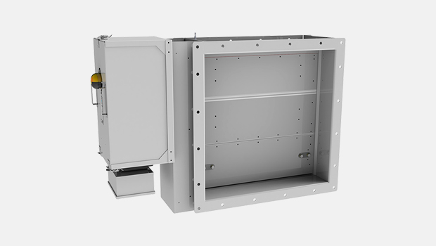
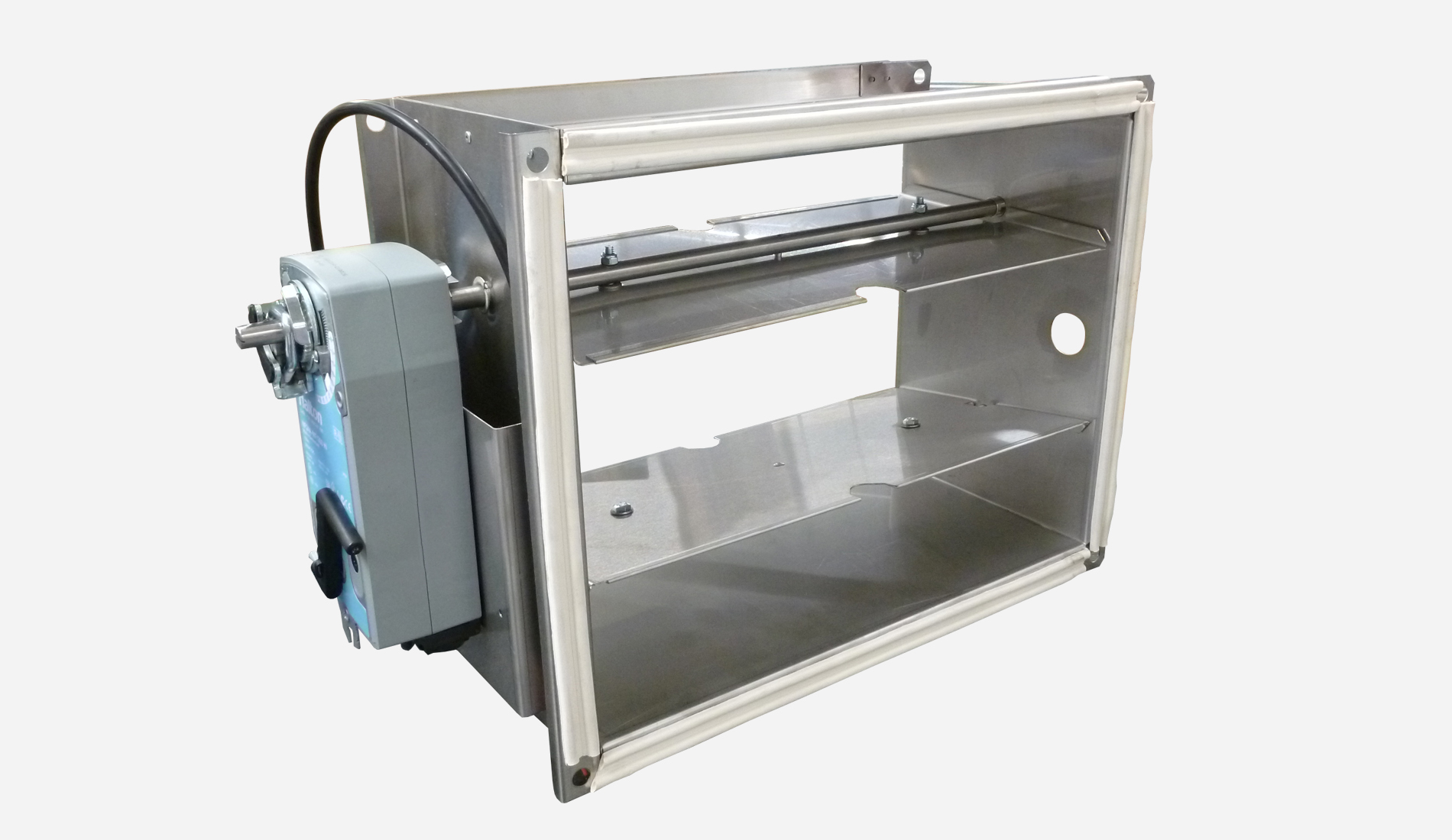
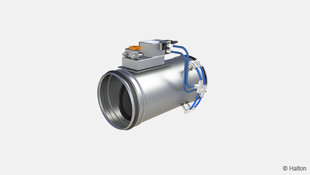
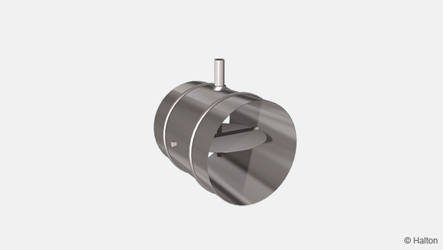
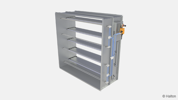
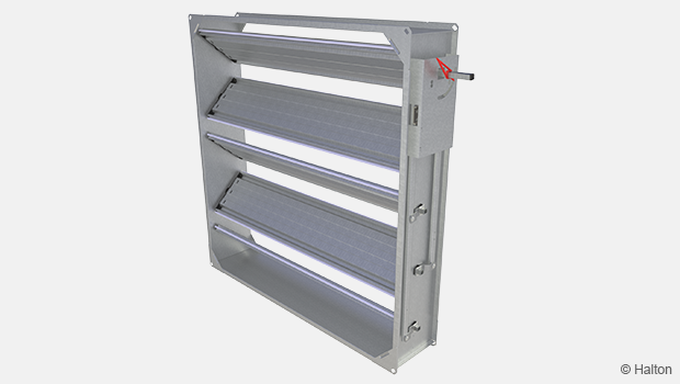
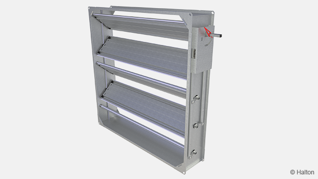
Halton UTA dampers are used to shut-off and balance airflow rates in high pressure ductwork.
Overview
- For shut-off and balancing of air intake and exhaust ducts
- A closed damper fulfils the requirement of leakage class 3 (EN1751:2014) for size ≥ 300×300 mm (stainless steel seals) and for size ≥ 150×150 mm (silicon seals)
- Classification of casing leakage (EN1751:2014) class C
- The outer frame of galvanized, painted or stainless steel. Blades of galvanized or stainless steel with double sheet construction. Blades contain stainless steel spring seals for low leakage. Silicon sealing as an option
- Earthing stud as standard
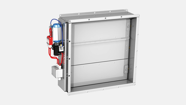
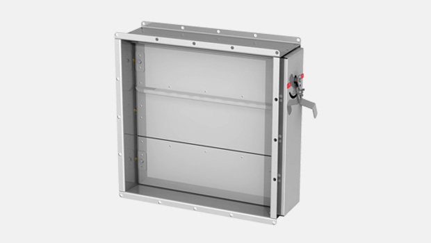
- Electrical, pneumatical or manual operation system available
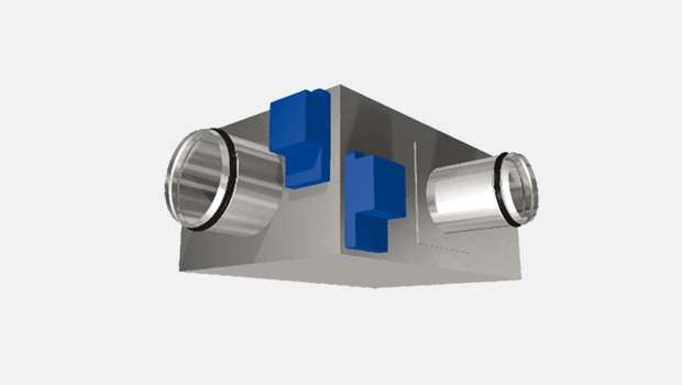
- UTA dampers can be supplied with connection pieces for round duct
- Maximum duct pressure for damper construction 5000 Pa and maximum air velocity of 15 m/s
- The normal operating temperature for the damper is from -50 ºC to +80 ºC. Actuator and component selection can affect this temperature range. Other temperatures available on request
- Available as ATEX certified
- SIL 2 safety assessment certificate available for the damper on specific terms
Specification
Halton UTA dampers are used to shut-off and balance airflow rates in high pressure ductworks. Dampers meet international standards for rectangular and round ducts. In the open position, the blades face the direction of flow and do not cause a significant pressure loss. The UTA is used as a shut-off, gas and balancing damper in applications where tightness and reliability are important.
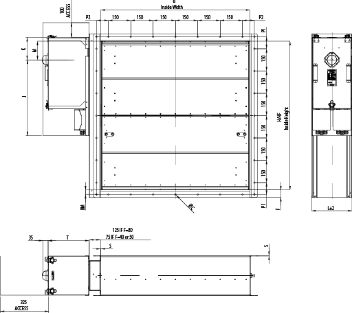
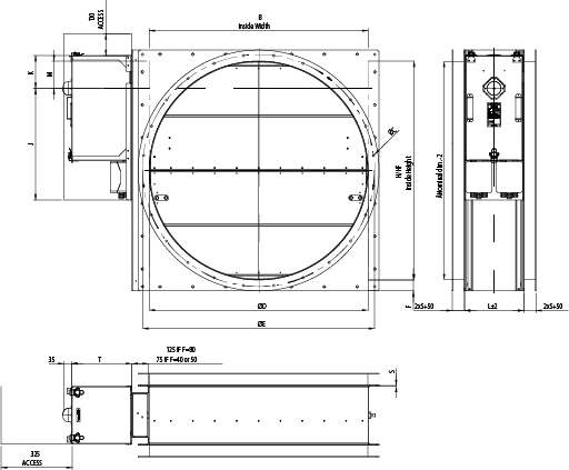
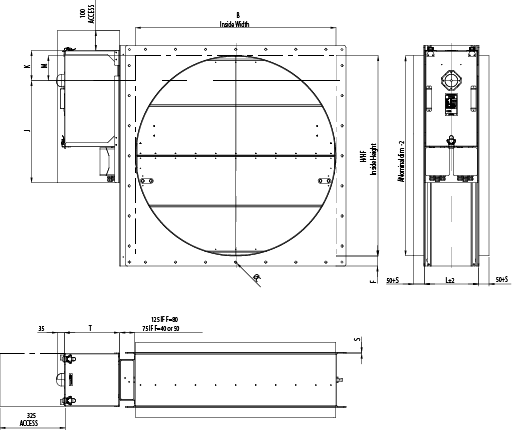
Dimensions and Material Thickness
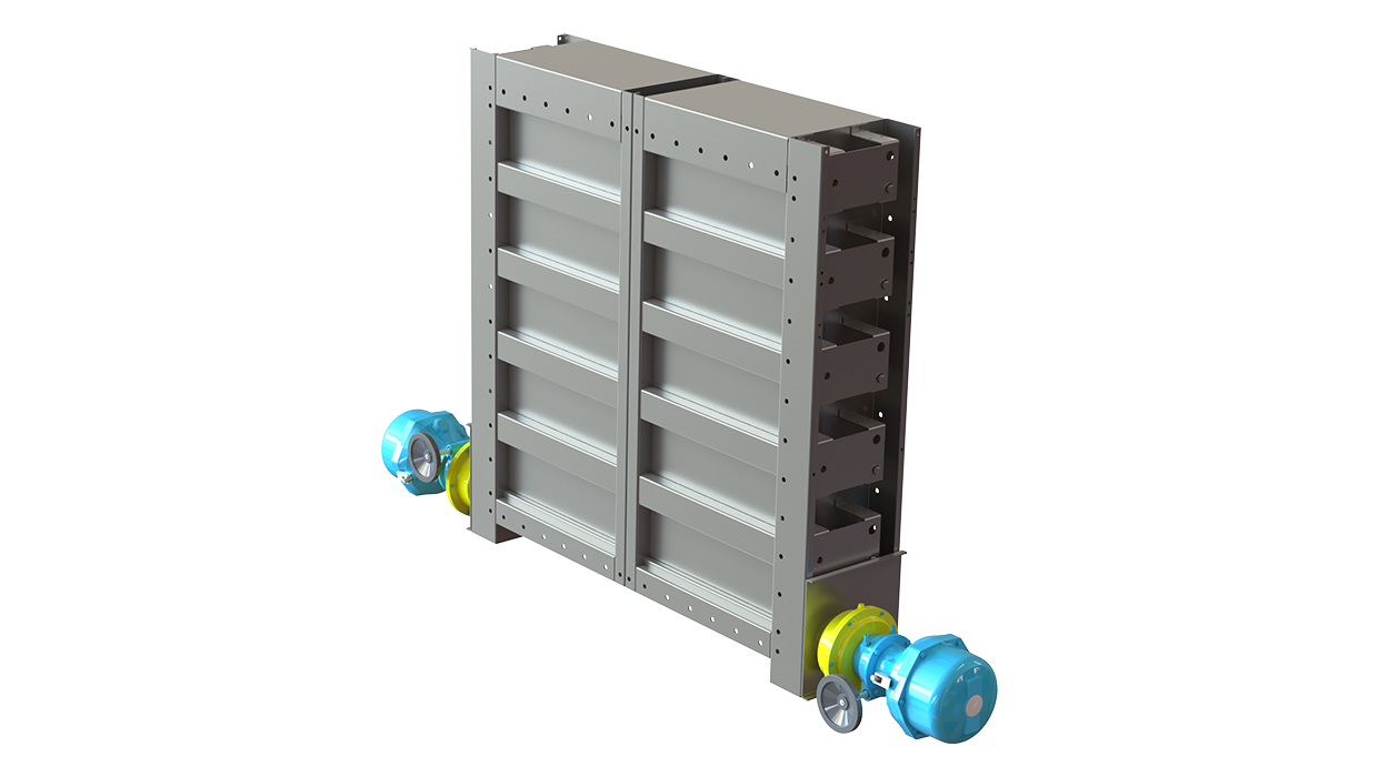
UTA dampers meet international standards for both rectangular (width B 100-1200 mm with 25 mm division and height H 100-1600 mm with 50 mm division) and circular ducts (Ø200-1250 mm). Modular constructions up to 2500×2600 mm available. For bigger sizes, contact Halton Marine.
Non-standard dimensions and flange drilling available on request. Standard flanges and drilling according to ISO 15138 standards. Frame thickness 3 or 5 mm. Blades are made of two sheets, each of them being 1 mm thick (sandwich design).
UTA, general drawings
| Actuator | J | K | T |
| AT100 | 430 | 150 | 145 |
| AT100 + Halton smart override | 510 | 150 | 255 |
| AT200 | 510 | 150 | 165 |
| AT200 + Halton smart override | 510 | 150 | 275 |
| AT300 | 510 | 180 | 190 |
| AT300 + Halton smart override | 510 | 180 | 300 |
| Belimo BF | 430 | 150 | 125 |
| Belimo BF (Damper height<200) | 430 | 90 | 125 |
| Schischek S | 430 | 150 | 145 |
| Schischek S (Damper height<200) | 430 | 90 | 145 |
| Schischek S + Halton smart override | 440 | 220 | 235 |
| Schischek M | 510 | 150 | 175 |
| Schischek M + Halton smart override | 440 | 220 | 165 |
| H Normal height |
HF Free height |
M Drive |
| 100 | 100 | 50 |
| 150 | 150 | 75 |
| 200 | 200 | 100 |
| 250 | 250 | 125 |
| 300 | 250 | 125 |
| 350 | 250 | 125 |
| 400 | 400 | 100 |
| 450 | 450 | 125 |
| 500 | 500 | 125 |
| 550 | 500 | 125 |
| 600 | 600 | 100 |
| 650 | 650 | 125 |
| 700 | 700 | 125 |
| 750 | 750 | 125 |
| 800 | 800 | 100 |
| 850 | 850 | 125 |
| 900 | 900 | 125 |
| 950 | 950 | 125 |
| 1000 | 1000 | 125 |
| 1050 | 1050 | 125 |
| 1100 | 1100 | 125 |
| 1150 | 1150 | 125 |
| 1200 | 1200 | 125 |
| 1250 | 1250 | 125 |
| 1300 | 1300 | 125 |
| 1350 | 1350 | 125 |
| 1400 | 1400 | 125 |
| 1450 | 1450 | 125 |
| 1500 | 1500 | 125 |
| 1550 | 1500 | 125 |
| 1600 | 1500 | 125 |
| Material Thickness |
Depth |
| 5 | L |
| 3 | 270 |
| 5 | 275 |
Flange dimensions according to ISO 15138
| Dimensions | Ø C | F | P1 | P2 | BM |
| If the longest side < 350 | 10 | 40 | 75…150 | 75…150 | 20 |
| If the longest side 351…1000 | 12 | 50 | 75…150 | 75…150 | 30 |
| If the longest side > 1001 | 14 | 80 | 75…150 | 75…150 | 40 |
Flange dimensions according to ISO 15138
| Nominal duct size (Ø D) |
Bolt circle (Ø E) | Bolt hole size | No. of bolts |
| 100 | 145 | 10 | 4 |
| 125 | 170 | 10 | 4 |
| 150 | 195 | 10 | 4 |
| 160 | 205 | 10 | 4 |
| 200 | 245 | 10 | 8 |
| 250 | 295 | 10 | 8 |
| 275 | 320 | 10 | 8 |
| 300 | 345 | 10 | 8 |
| 315 | 360 | 10 | 8 |
| 355 | 400 | 10 | 8 |
| 400 | 459 | 12 | 8 |
| 450 | 509 | 12 | 12 |
| 500 | 559 | 12 | 12 |
| 560 | 619 | 12 | 12 |
| 600 | 659 | 12 | 16 |
| 630 | 689 | 12 | 16 |
| 700 | 759 | 12 | 16 |
| 710 | 769 | 12 | 16 |
| 800 | 859 | 12 | 24 |
| 900 | 959 | 12 | 24 |
| 1000 | 1059 | 12 | 24 |
| 1120 | 1209 | 14 | 24 |
| 1200 | 1289 | 14 | 32 |
| 1250 | 1339 | 14 | 32 |
| 1400 | 1489 | 14 | 32 |
| Actuator | J | K | T |
| AT100 | 430 | 150 | 145 |
| AT100 + Halton smart override | 510 | 150 | 255 |
| AT200 | 510 | 150 | 165 |
| AT200 + Halton smart override | 510 | 150 | 275 |
| AT300 | 510 | 180 | 190 |
| AT300 + Halton smart override | 510 | 180 | 300 |
| Belimo BF | 430 | 150 | 125 |
| Belimo BF (Damper height<200) | 430 | 90 | 125 |
| Schischek S | 430 | 150 | 145 |
| Schischek S (Damper height<200) | 430 | 90 | 145 |
| Schischek S + Halton smart override | 440 | 220 | 235 |
| Schischek M | 510 | 150 | 175 |
| Schischek M + Halton smart override | 440 | 220 | 165 |
| H Normal height |
HF Free height |
M Drive |
| 100 | 100 | 50 |
| 150 | 150 | 75 |
| 200 | 200 | 100 |
| 250 | 250 | 125 |
| 300 | 250 | 125 |
| 350 | 250 | 125 |
| 400 | 400 | 100 |
| 450 | 450 | 125 |
| 500 | 500 | 125 |
| 550 | 500 | 125 |
| 600 | 600 | 100 |
| 650 | 650 | 125 |
| 700 | 700 | 125 |
| 750 | 750 | 125 |
| 800 | 800 | 100 |
| 850 | 850 | 125 |
| 900 | 900 | 125 |
| 950 | 950 | 125 |
| 1000 | 1000 | 125 |
| 1050 | 1050 | 125 |
| 1100 | 1100 | 125 |
| 1150 | 1150 | 125 |
| 1200 | 1200 | 125 |
| 1250 | 1250 | 125 |
| 1300 | 1300 | 125 |
| 1350 | 1350 | 125 |
| 1400 | 1400 | 125 |
| 1450 | 1450 | 125 |
| 1500 | 1500 | 125 |
| 1550 | 1500 | 125 |
| 1600 | 1500 | 125 |
Material and Finishing
| PART | MATERIAL | FINISHING |
| Frame | Carbon steel | Painted or galvanized |
| Frame | Stainless steel EN 1.4301 (AISI304), EN 1.4404 (AISI316L), EN 1.4432 (AISI316L) | Painted as an option |
| Blades | Steel | Galvanized |
| Blades | Stainless steel EN 1.4301 (AISI304), EN 1.4404 (AISI316L), EN 1.4432 (AISI316L) | – |
| Maintenance-free bearings |
Oil bronze. Stainless steel EN 1.4404 (AISI316L) available as an option. | – |
| Shafts | Stainless seel EN 1.4404 (AISI316L) | – |
Frame material thickness 3 or 5 mm.
Product Models
Halton UTA is available with following actuators:
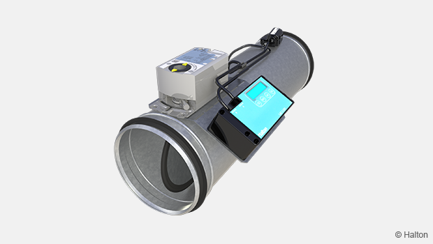
- UTA-EL: Electrical spring return actuator; standard actuators being 24 VAC/DC or 230 VAC or 120 VAC. Depending on the choice of actuator, the actuator might contain built-in open-closed limit switches. A wide range of Ex actuators available, including a one second closing time function as an option (for limited sizes).
- UTA-PNR: Pneumatic rotating actuator
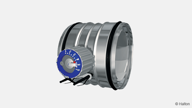
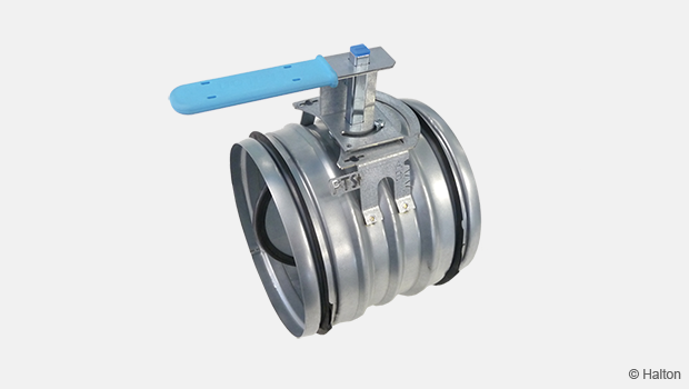
- UTA-MAN: Manual handle
HSO: Halton Smart Override function for HVAC damper black-start available for PNR and EL models. With automatic reset function when power and/or pneumatic air supply is reinstated.
A wide range of accessories available.
Weights
Weights of standard Halton UTA dampers (kg) without an actuator. Frame thickness 3 mm.
| HEIGHT (mm) |
B / WIDTH (mm) | |||||||||||
| 100 | 200 | 300 | 400 | 500 | 600 | 700 | 800 | 900 | 1000 | 1100 | 1200 | |
| 100 | 7,5 | 10,3 | 13,2 | 16,0 | 18,8 | 21,7 | 24,5 | 27,4 | 30,2 | 33 | 35,9 | 38,7 |
| 200 | 10,8 | 13,6 | 16,5 | 19,3 | 22,2 | 25,0 | 27,8 | 30,7 | 33,5 | 36,4 | 39,2 | 42,0 |
| 300 | 14,1 | 17,0 | 19,8 | 22,7 | 25,5 | 28,3 | 31,2 | 34,0 | 36,9 | 39,7 | 42,5 | 45,4 |
| 400 | 18,7 | 22,0 | 25,3 | 28,6 | 31,9 | 35,2 | 38,5 | 41,8 | 45,1 | 48,4 | 51,6 | 54,9 |
| 500 | 22,5 | 25,8 | 29,1 | 32,4 | 35,7 | 39,0 | 42,3 | 45,6 | 48,8 | 52,1 | 55,4 | 58,7 |
| 600 | 27,1 | 30,9 | 34,6 | 38,3 | 42,1 | 45,8 | 49,6 | 53,3 | 57,0 | 60,8 | 64,5 | 68,3 |
| 700 | 30,9 | 34,6 | 38,4 | 42,1 | 45,9 | 49,6 | 53,3 | 57,1 | 60,8 | 64,6 | 68,3 | 72,0 |
| 800 | 35,5 | 39,7 | 43,9 | 48,1 | 52,3 | 56,5 | 60,7 | 64,8 | 69,0 | 73,2 | 77,4 | 81,6 |
| 900 | 39,3 | 43,5 | 47,7 | 51,9 | 56,1 | 60,2 | 64,4 | 68,6 | 72,8 | 77,0 | 81,2 | 85,4 |
| 1000 | 43,1 | 47,3 | 51,5 | 55,6 | 59,8 | 64,0 | 68,2 | 72,4 | 76,6 | 80,8 | 85,0 | 89,2 |
| 1100 | 47,7 | 52,3 | 57,0 | 61,6 | 66,2 | 70,9 | 75,5 | 80,2 | 84,8 | 89,4 | 94,1 | 98,7 |
| 1200 | 51,5 | 56,1 | 60,7 | 65,4 | 70,0 | 74,7 | 79,3 | 83,9 | 88,6 | 93,2 | 97,9 | 102,5 |
| 1300 | 56,1 | 61,2 | 66,2 | 71,3 | 76,4 | 81,5 | 86,6 | 91,7 | 96,8 | 101,9 | 107,0 | 112,1 |
| 1400 | 59,8 | 64,9 | 70,0 | 75,1 | 80,2 | 85,3 | 90,4 | 95,5 | 100,6 | 105,7 | 110,7 | 115,8 |
| 1500 | 63,6 | 68,7 | 73,8 | 78,9 | 84,0 | 89,1 | 94,2 | 99,3 | 104,3 | 109,4 | 114,5 | 119,6 |
| 1600 | 67,4 | 72,5 | 77,6 | 82,7 | 87,8 | 92,9 | 97,9 | 103,0 | 108,1 | 113,2 | 118,3 | 123,4 |
| D2 ØD (mm) |
WEIGHT kg |
| 100 | 9 |
| 125 | 10 |
| 160 | 14 |
| 200 | 18 |
| 250 | 22 |
| 315 | 25 |
| 400 | 38 |
| 500 | 47 |
| 630 | 59 |
| 800 | 86 |
| 1000 | 109 |
| 1250 | 148 |
Flanges according to ISO 15138.
Weights of standard Halton UTA dampers (kg) without an actuator. Frame thickness 5 mm.
| HEIGHT (mm) |
B / WIDTH (mm) | |||||||||||
| 100 | 200 | 300 | 400 | 500 | 600 | 700 | 800 | 900 | 1000 | 1100 | 1200 | |
| 100 | 9,0 | 13,2 | 17,5 | 21,7 | 26,0 | 30,2 | 34,5 | 38,7 | 42,9 | 47,2 | 51,4 | 55,7 |
| 200 | 13,7 | 18,0 | 22,2 | 26,5 | 30,7 | 34,9 | 39,2 | 43,4 | 47,7 | 51,9 | 56,2 | 60,4 |
| 300 | 18,5 | 22,7 | 26,9 | 31,2 | 35,4 | 39,7 | 43,9 | 48,2 | 52,4 | 56,7 | 60,9 | 65,2 |
| 400 | 24,5 | 29,2 | 33,9 | 38,5 | 43,2 | 47,9 | 52,6 | 57,3 | 62,0 | 66,7 | 71,4 | 76,1 |
| 500 | 29,6 | 34,3 | 39,0 | 43,7 | 48,4 | 53,1 | 57,8 | 62,5 | 67,2 | 71,9 | 76,6 | 81,3 |
| 600 | 35,7 | 40,8 | 46,0 | 51,1 | 56,2 | 61,4 | 66,5 | 71,7 | 76,8 | 82,0 | 87,1 | 92,3 |
| 700 | 40,8 | 46,0 | 51,1 | 56,3 | 61,4 | 66,6 | 71,7 | 76,9 | 82,0 | 87,2 | 92,3 | 97,5 |
| 800 | 46,9 | 52,5 | 58,0 | 63,6 | 69,2 | 74,8 | 80,4 | 86,0 | 91,6 | 97,2 | 102,8 | 108,4 |
| 900 | 52,0 | 57,6 | 63,2 | 68,8 | 74,4 | 80,0 | 85,6 | 91,2 | 96,8 | 102,4 | 108,0 | 113,6 |
| 1000 | 57,2 | 62,8 | 68,4 | 74,0 | 79,6 | 85,2 | 90,8 | 96,4 | 102,0 | 107,6 | 113,2 | 118,8 |
| 1100 | 63,2 | 69,3 | 75,3 | 81,4 | 87,4 | 93,5 | 99,5 | 105,6 | 111,6 | 117,7 | 123,7 | 129,7 |
| 1200 | 68,4 | 74,5 | 80,5 | 86,6 | 92,6 | 98,7 | 104,7 | 110,7 | 116,8 | 122,8 | 128,9 | 134,9 |
| 1300 | 74,4 | 80,9 | 87,4 | 93,9 | 100,4 | 106,9 | 113,4 | 119,9 | 126,4 | 132,9 | 139,4 | 145,9 |
| 1400 | 79,6 | 86,1 | 92,6 | 99,1 | 105,6 | 112,1 | 118,6 | 125,1 | 131,6 | 138,1 | 144,6 | 151,1 |
| 1500 | 84,8 | 91,3 | 97,8 | 104,3 | 110,8 | 117,3 | 123,8 | 130,3 | 136,8 | 143,3 | 149,8 | 156,3 |
| 1600 | 90,0 | 96,5 | 103,0 | 109,5 | 116,0 | 122,5 | 129,0 | 135,5 | 142,0 | 148,5 | 155,0 | 161,4 |
| D2 ØD (mm) |
WEIGHT kg |
| 100 | 12 |
| 125 | 13 |
| 160 | 19 |
| 200 | 24 |
| 250 | 26 |
| 315 | 36 |
| 400 | 54 |
| 500 | 68 |
| 630 | 84 |
| 800 | 121 |
| 1000 | 154 |
| 1250 | 212 |
Flanges according to ISO 15138.
Installation
Installation on wall or roof.
At wall installation the blade orientation must always be in horizontal plane.
Installation and maintenance instructions are with each damper delivery. Copies of Operation and Maintenance manuals are available from Halton Marine Sales offices and distributors.
Product Code
(S)=Shape of Connection
(A) Circular on one side
(C) Circular on both sides
(R) Rectangular
(W)=Width
100-1200
(H)=Height
100-1200
(D)=Diameter
100-1200
(SM)=Blade Seal Material
(SI) Silicon
(AS) Stainless Steel EN1.4404
(EX)=Atex Certification
(NA) No
(X1) ATEX Certified damper [please fill]
(SF)=Flange Option
(AS) Stainless steel 1 mm EN1.4404
(CS) Carbon steel 1 mm
(LS) Stainless steel 1 mm EN1.4432
(SS) Stainless steel 1 mm EN1.4301
(MA)=Material Blades
(AS) Stainless steel 1 mm EN1.4404
(CS) Carbon steel 1 mm
(LS) Stainless steel 1 mm EN1.4432
(SS) Stainless steel 1 mm EN1.4301
(FM)=Frame Material
(A3) Stainless steel 3 mm EN1.4404
(A5) Stainless steel 5 mm EN1.4404
(C3) Carbon steel 3 mm
(C5) Carbon steel 5 mm
(L3) Stainless steel 3 mm EN1.4432
(L5) Stainless steel 5 mm EN1.4432
(S3) Stainless steel 3 mm EN1.4301
(S5) Stainless steel 5 mm EN1.4301
(FI)=Finishing
(HG) Hot galvanized
(NA) Acid treatment
(PN) Standard Painting grey RAL7001
(PX) Special Painting C5-M ISO12944
(BM)=Bearing Material
(BR) Phosphor-bronze-iolite
(AS) Stainless steel EN1.4404
(RE)=Actuator
(E1) Electric – Belimo, BF24-2-HL
(E3) Electric – belimo, BF230-2-HL
(E7) Electric – Belimo, BF120-HL
(E12) Electric – Belimo, EF230A-S2
(E13) Electric – Belimo, EF24A-S2
(C5) Electric – Elodrive, CSQP-15A1E 24V – Blocked
(C6) Electric – Elodrive, CSQP-15A2E 120/230V – Blocked
(I1) InMax – Schischek, 15-SF
(I2) InMax – Schischek, 15-SF VAS
(I3) InMax – Schischek, 15-SF1 VAS
(I4) InMax – Schischek, 8-SF
(I5) InMax – Schischek, 30-SF3
(I6) InMax – Schischek, 15-SF1
(I7) InMax – Schischek, 50-SF3
(I8) InMax – Schischek, 8-SF VAS
(P0) Pneumatic – Air Torque, AT101, Aluminium
(P3) Pneumatic – Air Torque, AT104, AISI316
(P4) Pneumatic – Air Torque, AT201 FA, Aluminium
(P5) Pneumatic – Air Torque, AT204 FA, AISI316
(Q5) Pneumatic -Air Torque, AT301 FA, Aluminium
(Q6) Pneumatic – Air Torque, AT304 FA, AISI316
(Q7) Pneumatic – Air Torque, AT351 FA, Aluminium, Module
(Q8) Pneumatic – Air Torque, AT404 FA, AISI316, Aluminium, Module
(U0) Pneumatic – Air Torque, AT301 FA STR, Aluminium
(U1) Pneumatic – Air Torque, AT304 FA STR, AISI316
(U2) Pneumatic – Air Torque, AT351 FA STR, Aluminium, Module
(U3) Pneumatic – Air Torque, AT404 FA STR, AISI316, Module
(Z2) Electric (EX) – Schischek, ExMax 15-SF
(Z4) Electric (EX) – Schischek, ExMax 15-SF VAS
(Z5) Electric (EX) – Schischek, ExMax 15-SF1 VAS
(Z6) Electric (EX) – Schischek, ExMax 8-SF
(Z7) Electric (EX) – Schischek, ExMax 15-SF1
(Z6) Electric (EX) – Schischek, ExMax 8-SF VAS
(Y1) Electric (EX) – Schischek, ExMax 30-SF3
(Y3) Electric (EX) – Schischek, ExMax 50-SF3
(MA) Manual
(AC)=Accessories
(E1) Junction box – Ensto, Plastic, IP66 & 67
(E2) EX junction box – Malux, GRP, IP66, T6
(L2) Limit switch 2 pcs – Bernstein, Plastic, IP65, Mechanical
(L4) EX Limit switch 2 pcs – Bartec, Plastic, IP66, Mechanical
(L5) EX Limit switch 4 pcs – Bartec, Plastic, IP66, Mechanical
(L6) EX Magnetic switch 2 pcs – Elobau, AISI6118, Magnetic
(L7) EX Magnetic switch 4 pcs – Elobau, AISI6118, Magnetic
(L8) EX Magnetic switch 2 pcs – Pepperl & Fuchs, AISI303, Inductive
(L9) EX Magnetic switch 4 pcs – Pepperl & Fuchs, AISI303, Inductive
(M1) Solenoid valve – SMC, Aluminium, 24 VDC
(M2) Solenoid valve – SMC, Aluminium, 230 VAC
(M3) EX solenoid valve – ASCO, Brass, 24 VDC
(M4) EX solenoid valve – ASCO, Brass, 230 VAC
(M5) EX solenoid valve – Bifold, AISI316, 24 VDC
(P1) Manual pneumatic valve – SMC, Aluminium
(P2) Manual pneumatic valve – Bifold, AISI316
(S3) Limit switch open/Close – Belimo, SN2, Mechanical
(SC) Cover box – Stainless steel
(ST) Pneumatic tubing & fittings – AISI316
(HO) Manual override handle – Halton, DOT
following choices are automatically included in (HO)
(O1) Manual override handle – Schischek, HV-SKU
(O2) Smart override handle – Halton, HSO
(O3) Smart override handle – Halton, HSO
(O4) Smart override handle – Halton, HSO
Code example
UTA1/R-100-100,SM=SI,EX=NA,SF=NR,MA=AS,FM=A3,FI=NA,BM=AS,RE=P0,ZT=Y,AC=E1,HO
Downloads
-
UTA – Gastight shut-off damper
Data
en
-
UTA – Kaasutiivis sulkupelti
Data
fi
-
UTA – Registre d’arrêt et d’équilibrage du débit d’air
Data
fr
-
UTA – Gasdichte Absperrklappe
Data
de
-
Halton UTA datasheet 2022
Data
English -
ATEX Certificate for Halton UTA, UTG, BLD, BRD
Data
English -
EAC Certificate for Halton FDA, FDB2, FDO, FDH, FCE, UTA, UTG, BDH, BRD, BLD
Data
Русский (ru) -
SIL 2 Safety Assessment Certificate
Data
English
ABD – Automaattinen säätöpelti (CE)
product
ABD – Automaattinen tasapainotuspelti
product
CID -01 – Täysin tiivis eristyspelti
product
Halton HFD – Ilmavirran säätöyksikkö
product
Halton Max MOC – Ilmamääräsäädin (VAV)
product
Halton Max MUC – Ultraääni ilmamääräsäädin (VAV)
product
Halton PRA – ilmavirran hallintapelti
product
Halton PTS – Ilmavirran säätöpelti (yksiläppäinen)
product
Halton RMC – Vakioilmavirtasäädin (CAV)
product
Halton UKV – Ilmavirran säädin
product
Halton UTK – Sälepelti
product
Halton UTT – Sälepelti
product
UTA – Kaasutiivis sulkupelti
product
UTG – Gastight shut-off damper
product
UTP – Tasapainotuspelti
product