Product / RXP
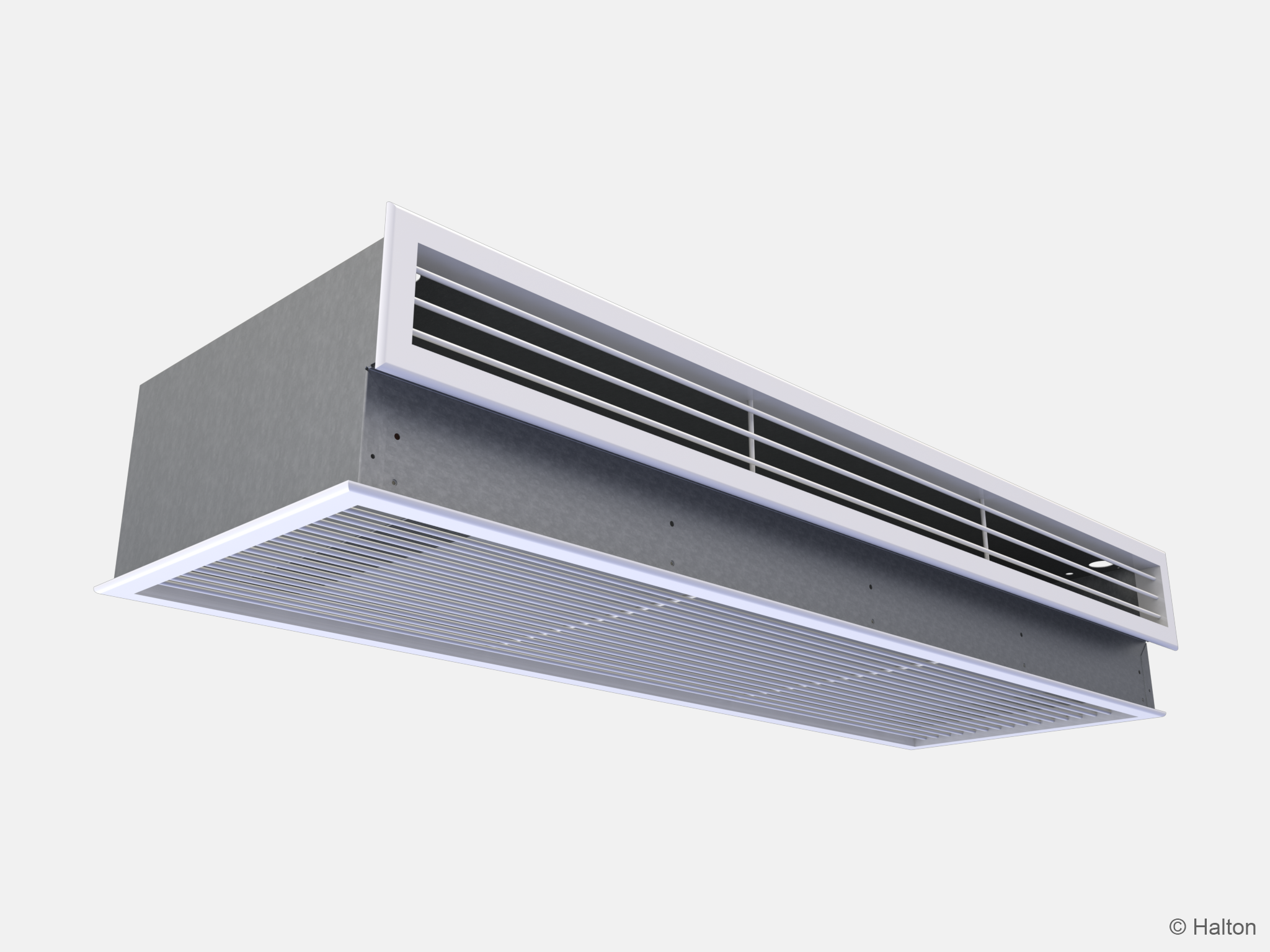
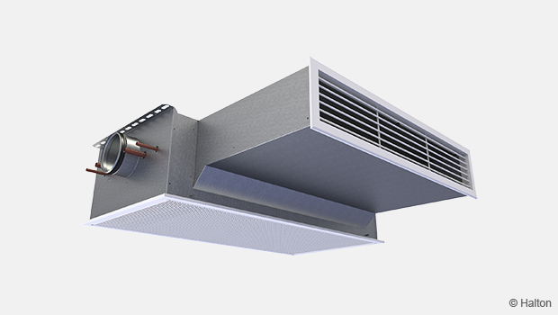
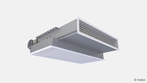
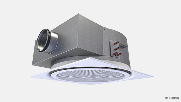
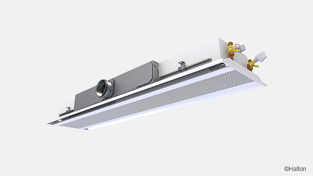
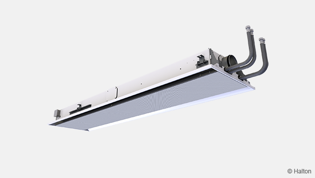
Halton Rex RXP – Poutre climatique
Soufflage dans les angles, ce qui garantit des conditions de confort même en cas de demande de froid importante.
- Poutre froide active avec soufflage sur 4 directions.
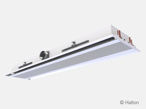
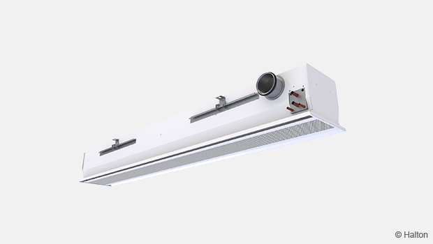
- Two product models with adjustable airflow using manual CAV or motorised VAV
- Standard model with boost airflow control
- Flexible model with 0-100% airflow control
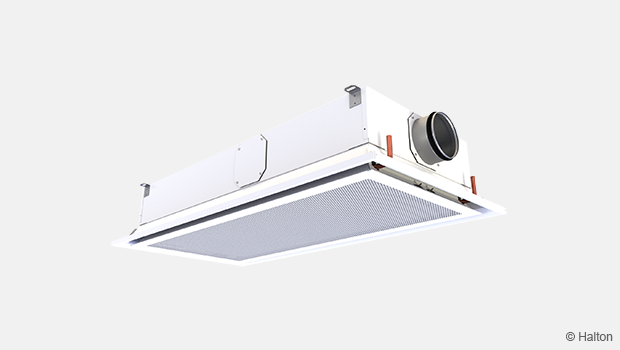

Présentation
Soufflage dans les angles, ce qui garantit des conditions de confort même en cas de demande de froid importante. Système silencieux garantissant un très bon confort intérieur.
Applications
- Applications types : bureaux, hôpitaux, écoles et espaces publics.
- Peut s’adapter aux solutions à la demande Halton.
Caractéristiques principales
- Poutre froide active avec soufflage sur 4 directions.
- Two product models with adjustable airflow using manual CAV or motorised VAV
- Standard model with boost airflow control
- Flexible model with 0-100% airflow control
- Soufflage dans les angles, ce qui garantit des conditions de confort même en cas de demande de froid importante.
- Model with Halton Workplace WRA, room automation system package
Les poutres climatiques Halton sont certifiées Eurovent Certita.

Fonction
L’air primaire entre dans le plénum de la poutre Halton Rex RXP, il est ensuite diffusé dans la pièce grâce aux buses et aux fentes de soufflage. La veine d’air venant des buses induit l’air ambiant venant de la batterie, où l’air est refroidi grâce à l’eau froide circulant dans la batterie. Les fentes de soufflage diffuse l’air horizontalement le long du plafond, ce qui évite les courants d’air.
Sur le schéma de fonctionnement de la poutre Halton Rex RXP, les flèches bleues indiquent l’air de soufflage sortant des fentes. Les flèches rouge indiquent l’air ambiant traversant le panneau de façade et la batterie.
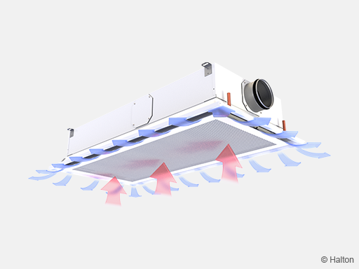
Fig.1. Operating principle of the Halton Rex RXP chilled beam
Contrôle de la Qualité de l’Air Halton Air Quality (HAQ) Halton Rex RXP, standard model
Le système Halton Air Quality (HAQ) est utilisé pour ajuster et contrôler le débit d’air additionnel du local. En fonctionnement normal, le débit d’air neuf est apporté à travers les buses. Quand un débit d’air additionnel est nécessaire, le système HAQ s’ouvre et apporte plus d’air.
Le système HAQ peut également être utilisé enfonctionnement à débit constant, il peut être utile pour ajuster le coefficient k en fonction de la pression. Cela évite le changement ou la fermeture des buses de la poutre.
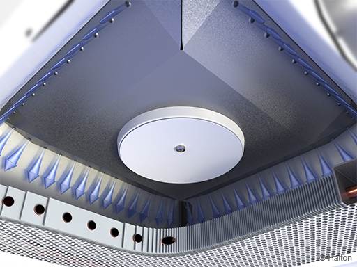
Fig.2. Fonction VAV : soufflage venant des buses (mode normal)
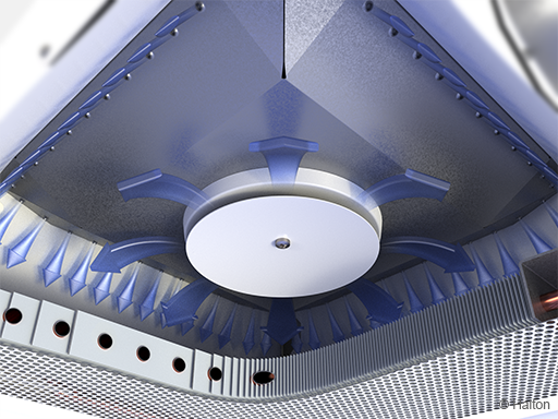
Fig.3. Fonction VAV avec HAQ : soufflage venant des buses et HAQ (mode boost)
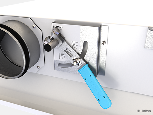
Fig.4. Réglage manuel du HAQ
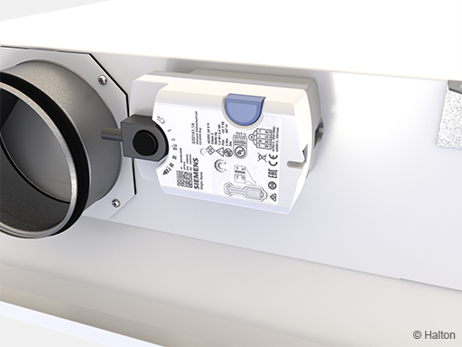
Fig.5. Motorisation électrique du HAQ
Halton Operation Model (OMD) in Halton Rex RXP, flexible model
Halton Operation Mode Damper (OMD) fully flexible airflow control is used for manual supply airflow adjustment or for motorized Variable Air Volume (VAV) control of the supply airflow rate. The OMD control flexibly combines nozzle and HAQ
The OMD control can be used as a Constant Air Volume (CAV) damper, that is, it can be used for adjusting the k-factor to achieve the correct airflow with a certain pressure level. This removes the need for changing or plugging the nozzles of the Halton Rex RXP chilled beam.
When the OMD control is equipped with a motorized actuator, fully flexible VAV control is achieved. It allows 1-3 VAV modes with minimum, normal and boost airflow settings.
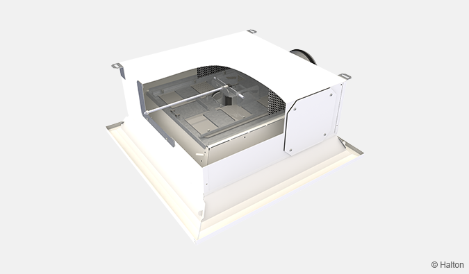
Fig. 6. Manual actuator of OMD control
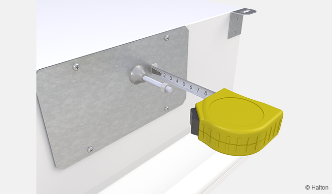
Fig. 7. Adjustment of the manual actuator of OMD control
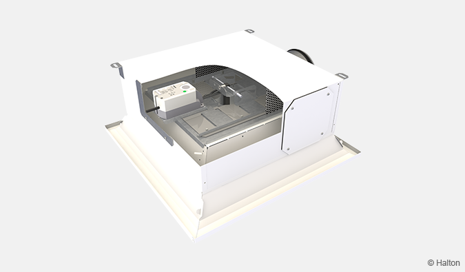
Fig. 8. Electric actuator of OMD controlairflow control providing full airflow flexibility with one nozzle configuration.
Données techniques
| Caractéristique | Description |
|---|---|
| Débit d’air | Max. airflow rate : 57 l/s ou 205 m³/h (RXP/S-E-1200); 65 l/s ou 234 m³/h (RXP/F-F-1200) |
| Dimensions | 600×600 mm ou 1200×600 mm |
| Water pressure drop |
Max. 18.6 kPa (RXP-1200, waterflow 0.1 kg/s) |
| Capacité de refroidissement | Up to 1700 W (RXP/S-E-1200, 100 Pa, 57 l/s, water inlet 14°C, water mass flow 0.1 kg/s, supply air 16°C) |
| Poids | 10–22 kg (RXP/S) et 17-31 kg (RXP/F) |
| Typical static pressure | 60–80 Pa |
| Water temperature |
|
Caractéristiques et options
|
Catégorie |
Caractèristique |
Options |
Description |
|
Taille et
|
Longueur L |
600, 1200 |
Deux longueurs. Largeur nominale 600 mm. |
|
Raccordement aéraulique E
|
S2, R2, L2 |
Raccordement usine direct, droit ou gauche Ø 125 mm. La position peut être changée sur site. |
|
|
S3, R3, L3 |
Raccordement usine direct, droit ou gauche Ø 160 mm. La position peut être changée sur site. Uniquement disponible pour L = 1200 mm et type de buses = E. |
||
|
Froid et
|
Type de batterie TC
|
C |
Batterie avec circuit d’eau froide. Raccordements en eau Ø 12 mm. |
|
H |
Batterie avec circuit d’eau froide et chaude. Raccordements en eau Ø 12 mm. | ||
|
Débit |
Type de buses S |
C, D, E |
3 options pour différents débits ou facteurs k. La buse C est la plus petite, E, la plus grande. |
|
Halton Air Quality (HAQ) AQ |
NA |
Pas de HAQ. Le coefficient k est déterminé par la taille et le type de buses (CAV). |
|
|
MA |
Manuel. Débit constant ou additionnel. Air neuf par les buses, additionnel par le HAQ. |
||
|
MO |
Motorisé. Débit d’air variable. Air neuf par les buses, additionnel par le HAQ. |
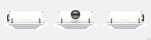
Fig.9. Raccordement: gauche, direct, droit
For more detailed information on the order code, see section Order code.
System package
Halton Workplace WRA room automation system package for Halton Rex RXP chilled beam, standard model (RXP/S)
Halton Workplace WRA is part of the Halton Workplace solution offering.
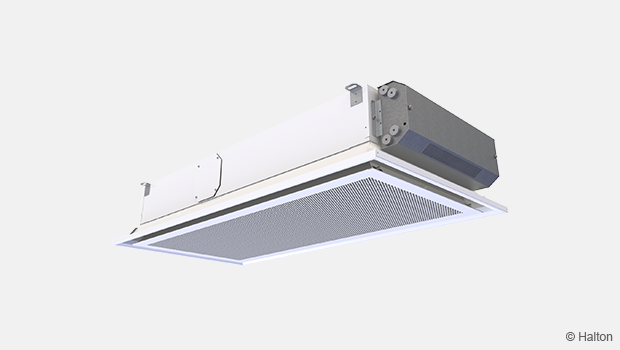
Fig. 10: Halton Workplace WRA room automation controller integrated to Halton Rex Expander (RXP) chilled beam
Halton Workplace WRA is a controller especially designed for controlling the automation system of office spaces and meeting rooms. It is used for controlling the ventilation airflow, room temperature, and indoor air quality.
The Halton Workplace WRA room automation package consists of a controller unit and optional components depending on customer needs: a wall panel and sensors for temperature, CO2, occupancy, pressure, and condensation.
There are options available for the controller unit and wall panel, depending on the number of controls and sensors required. The Halton Workplace WRA room automation controller is always combined with other Halton products for adaptable and high-level indoor climate.
Application area
- Controlling the ventilation airflow, room temperature, and indoor air quality in office spaces and meeting rooms
- The Halton Workplace WRA room automation controller is an important part of the Halton Workplace system, controlling room units and airflow control dampers
- Overall Halton Workplace System includes:
- Room air conditioning applications with Halton Workplace WRA room automation controller:
- Active chilled beams
- Exhaust units
- VAV dampers
- Active VAV diffusers
- Halton Max MDC zone control dampers
- Room air conditioning applications with Halton Workplace WRA room automation controller:
Key features
- Factory-tested controller and wiring, easy to install
- Pre-installed project-specific parameters, quick to commission
- Several operating modes based on occupancy, thermal comfort, and indoor air quality
- Enables fully flexible layout solutions for changing needs in office environments
- Highly energy-efficient and reliable system operation
Operating principle
The Halton Workplace WRA room automation controller operates with Variable Air Volume (VAV) dampers and active chilled beams of the Halton Workplace system. These are used for adjusting the ventilation airflow, room temperature, and indoor air quality in office spaces.
Each room unit in an office space can have its own dedicated Halton Workplace WRA room automation controller, or a single controller can control multiple room units. The Halton Workplace WRA room automation controller can automatically adjust the system according to the indoor environment level preferred by users. Each room unit having its own dedicated controller brings maximum flexibility.
Room automation: Halton Rex RXP active chilled beams with HAQ control and PTS damper, controlled with Halton Workplace WRA room automation controllers
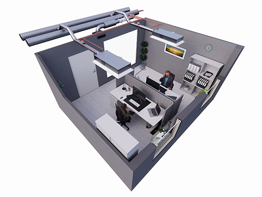
Fig. 11: Halton Rex RXP active chilled beams with HAQ control and PTS damper, controlled with Halton Workplace WRA room automation controllers in a double office room
Room automation description
In this configuration, two Halton Workplace WRA room automation controllers (type DXR2.E18-102A) control two Halton Rex RXP active chilled beams. Each chilled beam has heating and cooling valves, motorised Halton Air Quality (HAQ) control, as well as integrated CO2, pressure, and condensation sensors. A Halton PTS single-blade damper is used for controlling the minimum operating mode. The system also includes an exhaust VAV damper, window switch control, external occupancy sensor and a wall panel (type QMX3.P37) with a temperature sensor and display. One Halton Workplace WRA room automation controller can individually control up to four terminal units, and there can be several Halton Workplace WRA room automation controllers in the room.
Design criteria for room automation
- Chilled beam has heating and cooling valves
- Chilled beam has motorised HAQ control
- Chilled beam has integrated CO2, pressure, and condensation sensors
- External occupancy sensor
- Wall panel with temperature sensor and display
- Window switch control
- Optional PTS damper for controlling minimum airflow
- Exhaust airflow control
Schematic drawing

Fig. 12: Schematic drawing: Halton Rex RXP chilled beam (4-pipe) controlled with Halton Workplace WRA room automation controller
Equipment list
| Code | Equipment |
| RC | Controller unit |
| FG | Airflow damper actuator |
| FC | Airflow measurement |
| H | Water valve actuator |
| CS | Condensation sensor |
| OS | Occupancy sensor |
| PE | Pressure sensor |
| CO2 | CO2 sensor |
| WP | Wall panel |
| TE | Temperature sensor |
| TI | Temperature display |
| WS | Window switch control |
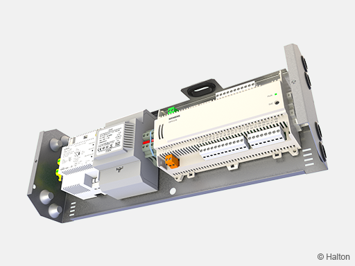
Fig. 13: Factory-installed Halton Workplace WRA room automation controller, type DXR2.E18-102A
Wiring diagram
For the wiring diagram of similar configuration, see the product page of Halton Workplace WRA room automation controller, section Installation information.
Components and order code examples for the system
- 2 x Active chilled beam: Halton Rex RXP
RXP/C-1200-S2, TC=H, AQ=MO, CO=SW, ZT=N - 1 x Exhaust unit: Halton AGC Exhaust grille + Halton PRL Plenum for grilles
AGC/N-400-100 FS=CL, ME=A, FI=PN, CO=W, ZT=N+PRL/F-400-100-160 - 1 x VAV damper: Halton Max Ultra Circular (MUC) or Halton Max One Circular (MOC)
MUC/G-160, MA=CS - 2 x standby, shut-off damper: Halton PTS
PTS/A-125, MA=CS, MO=B4, ZT=N - 2 x standby, shut-off damper: Halton PTS
PTS/A-125, MA=CS, MO=B4, ZT=N - Automation package: 2 x Halton Workplace WRA room automation controller unit with related components
WRA/RXP-E81-H3-EX4, WP=37, LC=NA, SE=CI, SW=NC, ST=IA, SL=OI, PM=P1, TC=H, CV=SP5, RV=NA, ZT=N
Note: For more information, see the product pages of the Halton Workplace WRA room automation controller
Cooling and heating water valve selection in Halton Workplace WRA room automation system package
Water valve selection is done in Halton Workplace WRA room automation system package. Water valve sizing depends on the number of secondary and primary chilled beam units that are controlled with single controller. One water valve is used to control the whole chilled beam group cooling or heating operated by one room controller. Water valve is sized for whole group when there are multiple chilled beams controlled with single controller unit. There can be one primary chilled beam with room controller and up to three secondary chilled beams. Water valve sizing for 1-4 chilled beams is shown below.
| Number of chilled beams (pcs.) | Water valve type | Size for cooling (DN) | Size for heating (DN) | Installation |
| 1 | ABQM | DN15 | DN15 | Integrated to chilled beam |
| 2 | ABQM | DN20 | DN15 | Loose |
| 3 | ABQM | DN20 | DN15 | Loose |
| 4 | ABQM | DN25 | DN15 | Loose |
| Number of chilled beams (pcs.) | Water valve type | Size for cooling (DN) | Size for heating (DN) | Installation |
| 1 | VPP46.. | DN15 | DN15 | Loose |
| 2 | VPP46.. | DN20 | DN15 | Loose |
| 3 | VPP46.. | DN20 | DN15 | Loose |
| 4 | VPP46.. | DN25 | DN15 | Loose |
Sélection rapide
Airflow
Halton Rex RXP, standard model
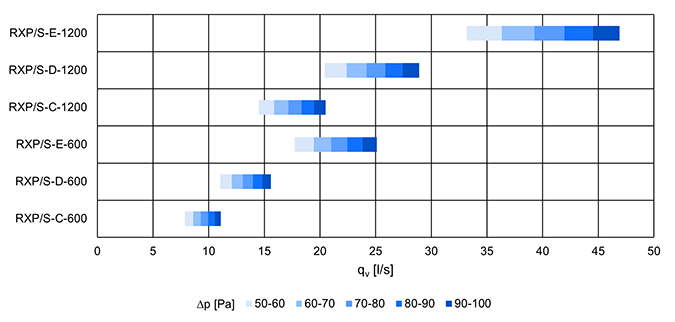
Fig.14. Airflow ranges in l/s for Halton Rex RXP, standard model without HAQ/with HAQ closed with different static chamber pressure levels

Fig.15. Airflow ranges in m3/h for Halton Rex RXP, standard model without HAQ/with HAQ closed with
different static chamber pressure levels
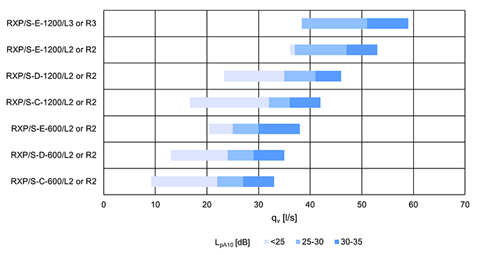
Fig. 16. Airflow ranges in l/s for Halton Rex RXP, standard model with HAQ @70 Pa total pressure
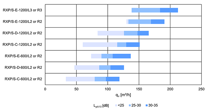
Fig. 17. Airflow ranges in m3/h for Halton Rex RXP standard model with HAQ @70 Pa total pressure
Halton Rex RXP, flexible model
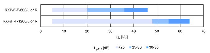
Fig. 18. Airflow ranges in l/s for Halton Rex RXP flexible model @70 Pa total pressure
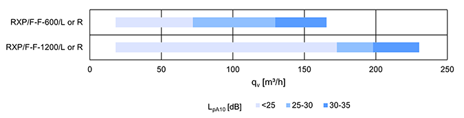
Fig. 19. Airflow ranges in m3/h for Halton Rex RXP flexible model @70 Pa total pressure
Cooling capacity
Halton Rex RXP, standard model
|
Product |
Inlet/outlet water temp. |
Room temp. |
Chamber pressure |
Water mass flow |
Airflow |
Capacity |
||
|
Water |
Air (18°C) |
Total |
||||||
|
RXP/C-600 |
15/17 |
25 |
75 |
0.032 |
10 |
269 |
81 |
350 |
|
RXP/D-600 |
0.038 |
14 |
315 |
114 |
429 |
|||
|
RXP/E-600 |
0.049 |
22 |
407 |
183 |
590 |
|||
|
RXP/C-1200 |
15/18 |
0.043 |
18 |
536 |
150 |
686 |
||
|
RXP/D-1200 |
0.054 |
25 |
676 |
211 |
887 |
|||
|
RXP/E-1200 |
0.063 |
41 |
790 |
343 |
1133 |
|||
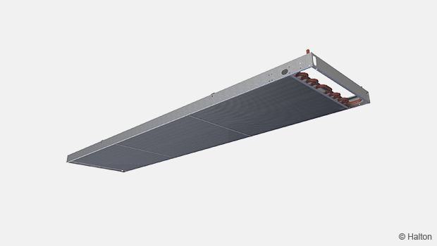
Structure and materials
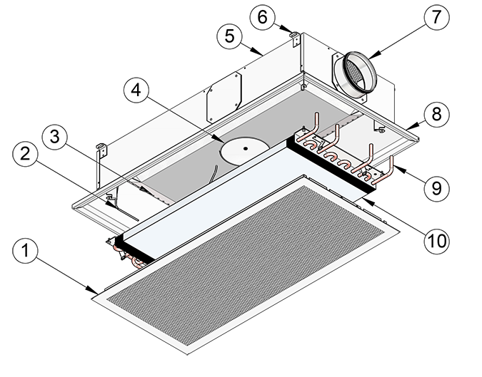
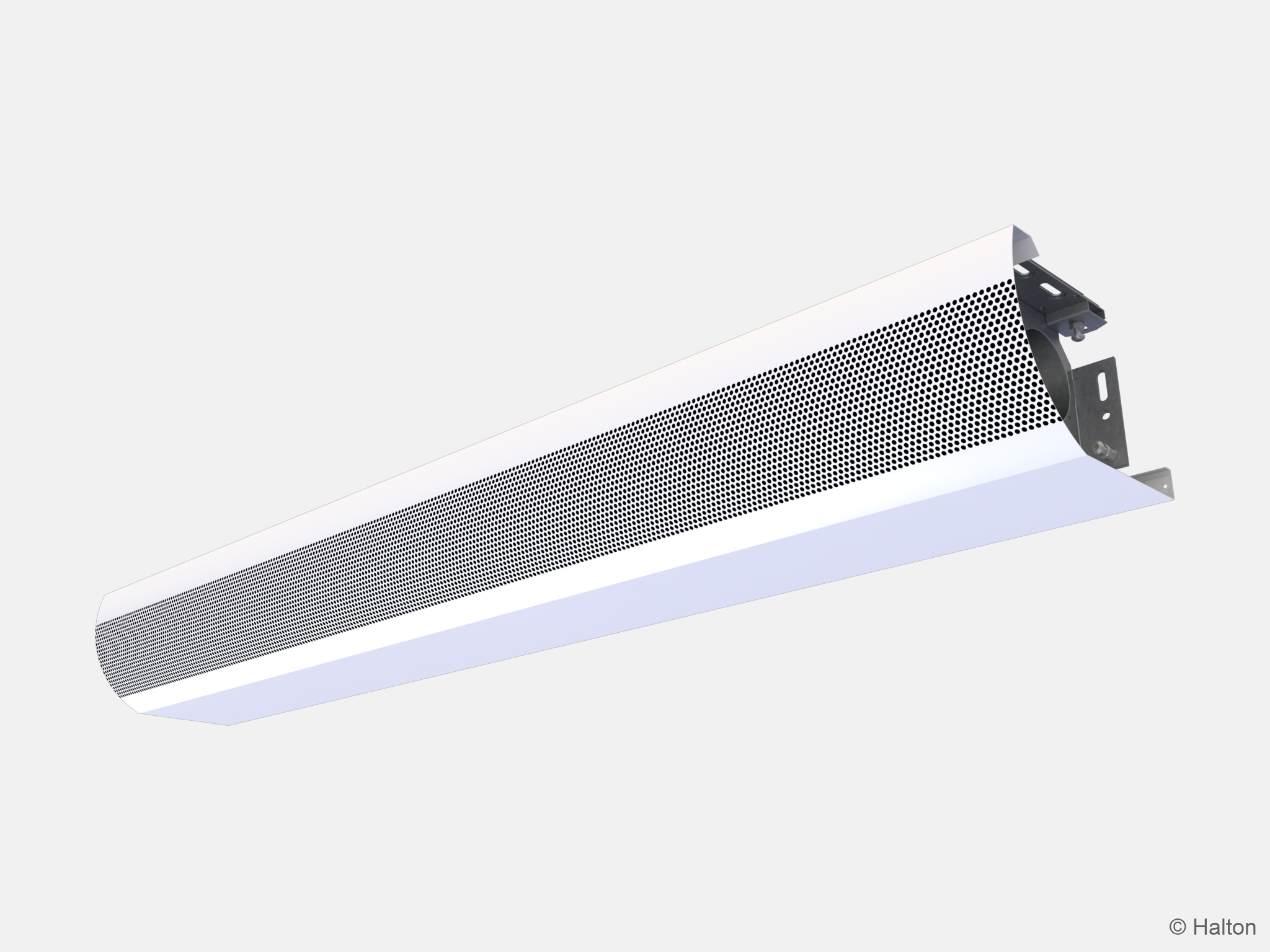
Fig.20. Halton Rex RXP
|
No. |
Part | Description |
|
1 |
Front panel |
|
|
2 |
Pressure measurement tube | Polyvinyl chloride |
|
3 |
Nozzles | Galvanised steel |
|
4 |
HAQ control |
|
|
||
|
5 |
Plenum |
|
|
6 |
Brackets | Galvanised steel |
| 7 | Spigot | Galvanised steel |
| 8 | Frame |
|
| 9 | Connection pipes | Copper. Ø 12 mm with a wall thickness of 0.9–1.0 mm, fulfilling the requirements of European Standard EN 1057:1996. |
| 10 | Coil/Heat exchanger |
|
Dimensions and weight
The dimensions are given in millimetres (mm).
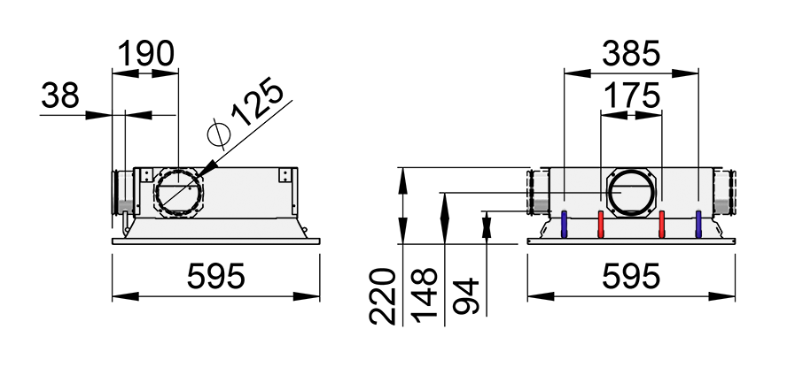
Fig.21. Halton Rex RXP, standard model dimensions (RXP/S-600)
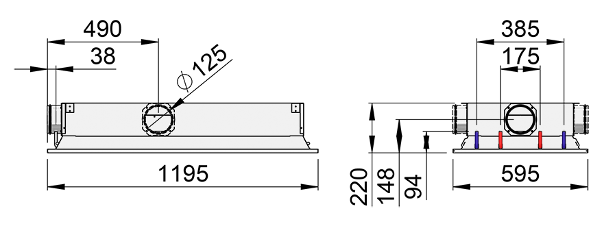
Fig.22. Halton Rex RXP, standard model dimensions (RXP/S-1200)
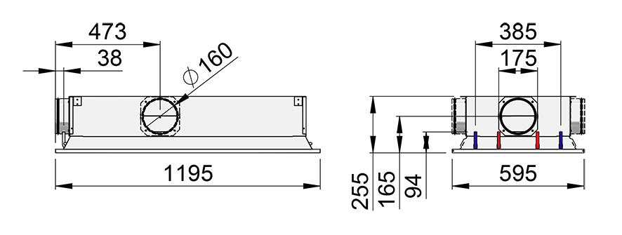
Fig.23. Halton Rex RXP, standard and flexible model dimensions (RXP/S or RXP/F-1200)
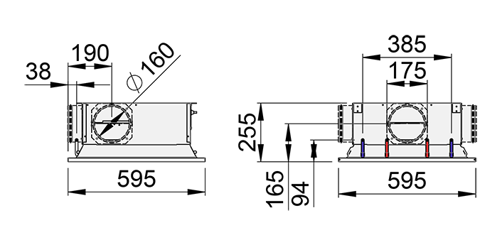
Fig. 24. Halton Rex RXP, flexible model dimensions (RXP/F-600)
Weight:
|
Product |
AQ model |
Dry mass (excl. water) [kg] |
Water volume [l] |
|
RXP/S-*- 600 |
NA |
10.5 |
0.5 |
|
MA |
11.4 |
||
|
MO |
11.6 |
||
|
RXP/S-*-1200 |
NA |
20.9 |
1.2 |
| MA | 21.8 | ||
| MO | 22.1 |
* Nozzle type, see section Order code.
|
Product |
CN model |
Dry mass (excl. water) [kg] |
Water volume [l] |
|
RXP/F-F-600 |
– |
– |
0.5 |
|
MA |
16.5 |
||
|
MO |
17.0 |
||
|
RXP/F-F-1200 |
– |
– |
1.2 |
| MA | 30.4 | ||
| MO | 31.0 |
Spécifications
La poutre Halton Rex RXP devra répondre aux besoins suivants :
Structure
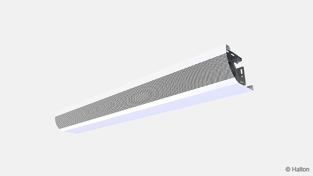
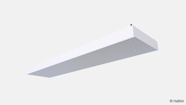
- Reprise de l’air ambiant à travers le panneau de façade perforé.
- Façade démontable pour la maintenance et le nettoyage.
- Démontage ne nécessitant pas d’outil spécial.
- Diffusion sur 4 directions.
- Largeur 595 mm, hauteur 220 mm.
- Raccordement en air primaire 125 mm.
- Modification de la position du diamètre d’entrée sans outil.
- Prises de pression pour mesures du débits d’air.
- Pression maximale de fonctionnement en eau 1.0 MPa.
Matériaux
- Plénum, cadre et façade en acier galvanisé.
- Parties visibles blanches, peintes en RAL 9003, 20% de brillance.
- Tubes en cuivre.
- Epaisseur des tubes 0.9–1.0 mm.
- Joints brasés.
- Joints des tubes testés en usine.
- Ailettes de la batterie en aluminium.
Emballage et identification
- Protection du produit par un film plastique.
- Diamètre air primaire et tubes d’eau obturés pendant le transport.
- Emballage carton.
- Le produit est identifié par un numéro de série imprimé sur une étiquette sur le produit et sur le
cart on d’emballage
Installation
La position du raccordement en air primaire ainsi que des raccordements en eau doit être identifiée. Le piquage en air peut être du même côté que les
raccordements en eau comme du côté opposé. Si besoin, la position du piquage en air peut être modifiée sur site.
La position du système HAQ (option) doit également être prise en compte pour s’assurer de l’accès au moteur. Le moteur est situé au milieu du côté gauche de l’unité.
La poutre Halton Rex RXP peut être montée directement dans le faux-plafond (H = 220 mm) ou suspendue avec des tiges filetées (8 mm). Les équerres de fixation nécessaires au montage sont placées sur le côté de l’unité.
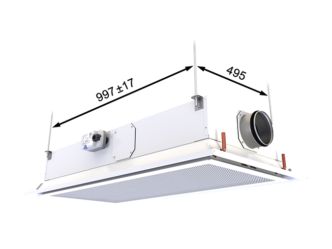
Fig. 25. Installation points of Halton Rex RXP 1200, standard and flexible model
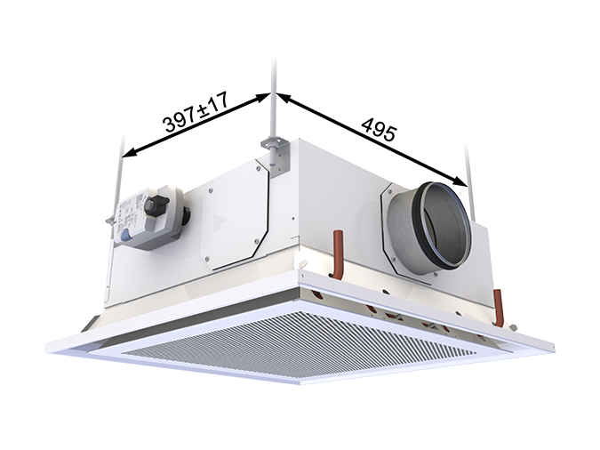
Fig. 26. Installation points of Halton Rex RXP 600, standard model
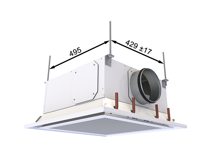
Fig. 27. Installation points of Halton Rex RXP 600, flexible model
Parce que la poutre Halton RXP ne comporte aucune partie mobile, aucun système anti-vibration n’est nécessaire pour le montage de l’unité.
Il est recommandé de monter l’arrivée en eau de la batterie au-dessus de la batterie pour prévoir la purge du système.
La pression maximale de fonctionnement est de 1.0 MPa.
Mise en service
Rafraîchissement
Le débit massique d’eau froide recommandé se situe entre 0,02 et 0,10 kg/s ; il correspond à une augmentation de température de 1 à 4 °C entre l’entrée et la sortie de la batterie. Afin d’éviter toute condensation, La température d’eau recommandée à l’entrée de l’échangeur de chaleur se situe entre 14 et 16 °C.
Chauffage
Le débit massique d’eau chaude recommandé se situe entre 0,01 et 0,04 kg/s ; il correspond à une chute de température de 5 à 15 °C entre l’entrée et la sortie de la batterie. La température d’eau maximale à l’entrée de la batterie est de 35 °C.
Équilibrage et réglage des débits d’eau
Équilibrer les débits d’eau de la poutre en agissant sur les vannes de réglage placées à la sortie des circuits d’eau de refroidissement et de chauffage. La capacité de refroidissement et la capacité de chauffage de la poutre climatique sont commandées par régulation du débit massique d’eau.
Réglage du débit d’air primaire
Avec une poutre Halton Rex RXP qui n’est pas équipée du système Halton Air Quality (HAQ), le débit d’air dépend de la pression dans la chambre et du type de buses.
Avec le HAQ inclus, la position du système HAQ doit être prise en compte.
La pression de la chambre peut être mesurée à l’aide des prises de pression positionnées sous la façade.
Le débit d’air total est calculé à l’aide de la formule ci-dessous.
![]()
Où :
qv Débit d’air l/s ou m³/h,
Δpm Valeur de la pression statique mesurée [Pa]
k Déterminé avec le tableau
Halton Rex RXP, standard model
| Position of HAQ control | Control signal voltage [V] | k factor [l/s], total airflow (standard model) | |||||
| 600 | 1200 | ||||||
| C* | D* | E* | C* | D* | E* | ||
| 0/closed/no HAQ | 0-1 | 1,11 | 1,56 | 2,51 | 2,05 | 2,89 | 4,69 |
| 0,5 | 1,50 | 1,39 | 1,84 | 2,79 | 2,33 | 3,17 | 4,97 |
| 1 | 2 | 1,67 | 2,12 | 3,07 | 2,61 | 3,45 | 5,25 |
| 1,5 | 2,50 | 1,94 | 2,39 | 3,34 | 2,88 | 3,72 | 5,52 |
| 2 | 3 | 2,21 | 2,66 | 3,61 | 3,15 | 3,99 | 5,79 |
| 2,5 | 3,50 | 2,47 | 2,92 | 3,87 | 3,41 | 4,25 | 6,05 |
| 3 | 4 | 2,72 | 3,17 | 4,12 | 3,66 | 4,50 | 6,30 |
| 3,5 | 4,5 | 2,97 | 3,42 | 4,37 | 3,91 | 4,75 | 6,55 |
| 4 | 5 | 3,21 | 3,66 | 4,61 | 4,15 | 4,99 | 6,79 |
| 4,5 | 5,5 | 3,44 | 3,89 | 4,84 | 4,38 | 5,22 | 7,02 |
| 5 | 6 | 3,67 | 4,12 | 5,07 | 4,61 | 5,45 | 7,25 |
| 5,5 | 6,5 | 3,89 | 4,34 | 5,29 | 4,83 | 5,67 | 7,47 |
| 6 | 7 | 4,11 | 4,56 | 5,51 | 5,05 | 5,89 | 7,69 |
| 6,5 | 7,5 | 4,32 | 4,77 | 5,72 | 5,26 | 6,10 | 7,90 |
| 7 | 8 | 4,52 | 4,97 | 5,92 | 5,46 | 6,30 | 8,10 |
| 7,5 | 8,5 | 4,72 | 5,17 | 6,12 | 5,66 | 6,50 | 8,30 |
| 8 | 9 | 4,91 | 5,36 | 6,31 | 5,85 | 6,69 | 8,49 |
| 8,5 | 9,5 | 5,10 | 5,55 | 6,50 | 6,04 | 6,88 | 8,68 |
| 9 | 10 | 5,28 | 5,73 | 6,68 | 6,22 | 7,06 | 8,86 |
Table 1. The k factors with different HAQ control positions for Halton Rex RXP, standard model in l/s
*Nozzle types: C = Medium, D = Large, E = Extra large
| Position of HAQ control | Control signal voltage [V] | k factor [m³/h], total airflow (standard model) | |||||
| 600 | 1200 | ||||||
| C* | D* | E* | C* | D* | E* | ||
| 0/closed/no HAQ | 0-1 | 4,00 | 5,62 | 9,04 | 7,38 | 10,40 | 16,88 |
| 0,5 | 1,50 | 5,02 | 6,64 | 10,06 | 8,40 | 11,43 | 17,91 |
| 1 | 2 | 6,02 | 7,64 | 11,06 | 9,40 | 12,43 | 18,91 |
| 1,5 | 2,50 | 7,00 | 8,62 | 12,04 | 10,38 | 13,40 | 19,88 |
| 2 | 3 | 7,95 | 9,57 | 12,99 | 11,34 | 14,36 | 20,84 |
| 2,5 | 3,50 | 8,88 | 10,50 | 13,92 | 12,27 | 15,29 | 21,77 |
| 3 | 4 | 9,80 | 11,42 | 14,84 | 13,18 | 16,20 | 22,68 |
| 3,5 | 4,5 | 10,68 | 12,30 | 15,72 | 14,07 | 17,09 | 23,57 |
| 4 | 5 | 11,55 | 13,17 | 16,59 | 14,93 | 17,96 | 24,44 |
| 4,5 | 5,5 | 12,39 | 14,01 | 17,43 | 15,78 | 18,80 | 25,28 |
| 5 | 6 | 13,22 | 14,84 | 18,26 | 16,60 | 19,62 | 26,10 |
| 5,5 | 6,5 | 14,02 | 15,64 | 19,06 | 17,40 | 20,42 | 26,90 |
| 6 | 7 | 14,79 | 16,41 | 19,83 | 18,18 | 21,20 | 27,68 |
| 6,5 | 7,5 | 15,55 | 17,17 | 20,59 | 18,93 | 21,96 | 28,44 |
| 7 | 8 | 16,28 | 17,90 | 21,32 | 19,67 | 22,69 | 29,17 |
| 7,5 | 8,5 | 16,99 | 18,61 | 22,03 | 20,38 | 23,40 | 29,88 |
| 8 | 9 | 17,68 | 19,30 | 22,72 | 21,07 | 24,09 | 30,57 |
| 8,5 | 9,5 | 18,35 | 19,97 | 23,39 | 21,73 | 24,76 | 31,24 |
| 9 | 10 | 18,99 | 20,61 | 24,03 | 22,38 | 25,40 | 31,88 |
Table 2. The k factors with different HAQ control positions for Halton Rex RXP, standard model in m3/h
*Nozzle types: C = Medium, D = Large, E = Extra large
Halton Rex RXP, flexible model
| Distance measured for manual actuator [mm] | Control signal voltage for electric actuator [V] | k factor [l/s], total airflow (flexible model) | |||
| 600 | 1200 | ||||
| S* | L/R* | S* | L/R* | ||
| 33,0 | 0 | 0,19 | 0,18 | 0,26 | 0,22 |
| 36,2 | 0,5 | 0,32 | 0,30 | 0,32 | 0,26 |
| 39,4 | 1 | 0,82 | 0,79 | 0,80 | 1,58 |
| 42,6 | 1,5 | 1,35 | 1,33 | 2,16 | 2,58 |
| 45,7 | 2 | 1,60 | 1,60 | 2,74 | 2,95 |
| 48,9 | 2,5 | 1,78 | 1,79 | 2,69 | 3,12 |
| 52,1 | 3 | 1,86 | 1,88 | 3,08 | 3,21 |
| 55,3 | 3,5 | 1,93 | 1,94 | 3,16 | 3,28 |
| 58,4 | 4 | 1,95 | 1,97 | 3,19 | 3,34 |
| 61,6 | 4,5 | 2,23 | 2,22 | 3,29 | 3,56 |
| 64,8 | 5 | 2,68 | 2,65 | 3,48 | 3,99 |
| 68,0 | 5,5 | 3,08 | 3,11 | 3,93 | 4,38 |
| 71,1 | 6 | 3,56 | 3,50 | 4,37 | 4,91 |
| 74,3 | 6,5 | 3,95 | 3,85 | 4,86 | 5,42 |
| 77,5 | 7 | 4,39 | 4,30 | 5,26 | 5,90 |
| 80,7 | 7,5 | 4,80 | 4,72 | 5,78 | 6,42 |
| 83,8 | 8 | 5,18 | 5,10 | 6,25 | 6,95 |
| 87,0 | 8,5 | 5,56 | 5,43 | 6,80 | 7,46 |
| 90,2 | 9 | 5,92 | 5,77 | 7,45 | 7,96 |
| 93,4 | 9,5 | 6,23 | 6,08 | 7,90 | 8,39 |
| 96,5 | 10 | 6,19 | 6,08 | 8,26 | 8,57 |
Table 3. The k factors with different OMD control positions for Halton Rex RXP, flexible model in l/s
*Duct connections: S3 = Straight, L3 = Left, R3 = Right
| Distance measured for manual actuator [mm] | Control signal voltage for electric actuator [V] | k factor [m3/h], total airflow (flexible model) | |||
| 600 | 1200 | ||||
| S* | L/R* | S* | L/R* | ||
| 33,0 | 0 | 0,68 | 0,65 | 0,94 | 0,79 |
| 36,2 | 0,5 | 1,15 | 1,08 | 1,15 | 0,94 |
| 39,4 | 1 | 2,95 | 2,84 | 2,88 | 5,69 |
| 42,6 | 1,5 | 4,86 | 4,79 | 7,78 | 9,29 |
| 45,7 | 2 | 5,76 | 5,76 | 9,86 | 10,62 |
| 48,9 | 2,5 | 6,41 | 6,44 | 10,66 | 11,23 |
| 52,1 | 3 | 6,70 | 6,77 | 11,09 | 11,56 |
| 55,3 | 3,5 | 6,95 | 6,98 | 11,38 | 11,81 |
| 58,4 | 4 | 7,02 | 7,09 | 11,48 | 12,02 |
| 61,6 | 4,5 | 8,03 | 7,99 | 11,84 | 12,82 |
| 64,8 | 5 | 9,65 | 9,54 | 12,53 | 14,36 |
| 68,00 | 5,5 | 11,09 | 11,20 | 14,15 | 15,77 |
| 71,1 | 6 | 12,82 | 12,60 | 15,73 | 17,68 |
| 74,3 | 6,5 | 14,22 | 13,86 | 17,50 | 19,51 |
| 77,5 | 7 | 15,80 | 15,48 | 18,94 | 21,24 |
| 80,7 | 7,5 | 17,28 | 16,99 | 20,81 | 23,11 |
| 83,8 | 8 | 18,65 | 18,36 | 22,50 | 25,02 |
| 87,00 | 8,5 | 20,02 | 19,55 | 24,48 | 26,86 |
| 90,2 | 9 | 21,31 | 20,77 | 26,82 | 28,66 |
| 93,4 | 9,5 | 22,43 | 21,89 | 28,44 | 30,20 |
| 96,5 | 10 | 22,28 | 21,89 | 29,74 | 30,85 |
Table 4. The k factors with different OMD control positions for Halton Rex RXP, flexible model in m3/h
*Duct connections: S3 = Straight, L3 = Left, R3 = Right
Example 1:
The measured static chamber pressure is 70 Pa for RXP/E-600, and the position of the HAQ control is 3. The total airflow rate is 4.1*√(70) ≈ 34.3 l/s.
Example 2:
The OMD pressure measured from the measurement tap in RXP/F-F-600 S3 is 75 Pa. RXP/F-F-600 S3 is equipped with the manual actuator. The positions of the manual actuator can be moved with the metal rod shown in Fig. 24. The measured distance to the tip of metal rod is 40 mm. For calculating the total airflow rate, the k-value is taken from Table 4 (measured distance rounded to closest value in table), and calculated with the equation 0.82*√75 ≈ 7 l/s.
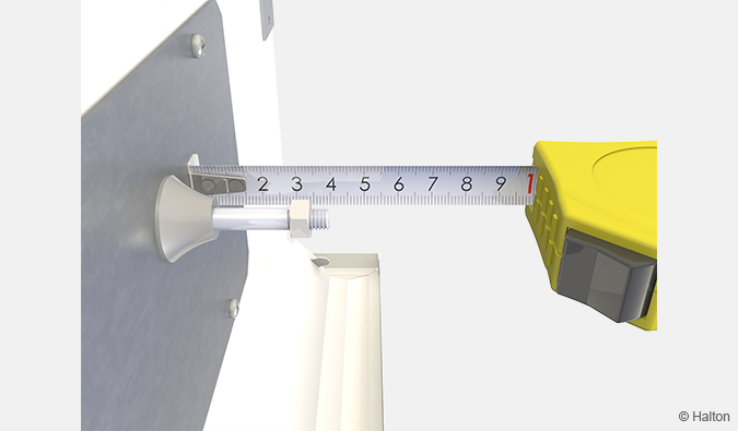
Fig. 28. Measurement of the distance for the position of the manual actuator
Code commande
RXP/M-S-L-E; SP-TC-CT-CN-VC-CO-ZT
| Main options | |
| M = Model | |
| S | Standard |
| F | Flexible |
| A | Autonomic |
| S = Type de buses | |
| C | Medium |
| D | Large |
| E | Extra large |
| F | Flexible |
| L = Longeur [mm] | |
| 600 ou 1200 | |
| E = Raccordement aéraulique | |
| S2 | Direct (Ø125) |
| R2 | Droit (Ø125) |
| L2 | Gauche (Ø125) |
| S3 | Direct (Ø160) |
| R3 | Droit (Ø160) |
| L3 | gauche (Ø160) |
| Autre options et accessoires | |
| SP = System package | |
| N | Non |
| Y | Oui |
| TC = Fonctions rafraîchissement / chauffage (type de batterie) | |
| C | Rafraîchissement |
| H | Rafraîchissement et chauffage |
| CT = Connection type (air and water) | |
| S | Direct |
| O | Opposé |
| CN = Control type | |
| NA | Non assigné |
| MA | Manuel |
| M1 | Motorisé (0…10 VDC) |
| M2 | Motorisé (Modbus RTU/BACnet MSTP) |
| VC = Velocity control (HVC) | |
| N | Non |
| Y | Oui |
| CO = Couleur | |
| SW | Blanc signalisation (RAL 9003) |
| W | Blanc pur (RAL 9010) |
| X | Couleur spéciale (RAL xxxx) |
| ZT = Produit spécial | |
| N | Non |
| Y | Oui (ETO) |
| Sub product (ordered separately) | |
| System package | Halton Workplace WRA |
| Room exhaust VAV damper | Halton Max MOC |
| Room exhaust VAV damper | Halton Max MUC |
Exemple de code commande
RXP/S-E-1200-S2, SP=N, TC=C, CT=S, CN=NA, VC=N, CO=SW, ZT=N
Downloads
-
Halton Rex RXP – Chilled beam
Data
en
-
Halton Rex RXP – Ilmastointipalkki
Data
fi
-
Halton Rex RXP – Poutre climatique
Data
fr
-
Halton Rex RXP – Kylbaffel
Data
se
-
Halton Rex RXP – Technical description
Data
English (en) -
Halton Rex RXP – Teknisk beskrivning (Standard och Flexible modeller)
Data
Svenska (sv) -
Halton Rex RXP – Tekninen kuvaus (Standard- ja Flexible-mallit)
Data
Suomi (fi) -
Halton Rex RXP, Standard model – Installation, commissioning and maintenance guide
Data
English (en) -
Eurovent Certification for Chilled Beams
Data
English (en) -
Enviromental Product Declaration (EPD) – Halton chilled beams, VAV type
Data
English (en)
Halton CaBeam – Chilled beam for exposed wall installation
product
Halton CaBeam – Chilled beam for integrated installation
product
Halton CaBeam – Chilled beam for recessed installation
product
Halton CBD – Poutre climatique active
product
Halton CBH – Poutre climatique active – Montage sans faux-plafond
product
Halton CHB – Poutre climatique active avec fonction grande vitesse facultative
product
Halton CHH – Poutre climatique active – Montage en soffite
product
Halton CPA – Poutre statique
product
Halton CPT – Poutre statique
product
Halton CSW – Poutre active à jet tourbillonnaire
product
Halton Rex Exposed VAV (REO) – Poutre active VAV
product
Halton Rex RE6 – Poutre climatique
product
Halton Rex REE – Poutre climatique
product
Halton Rex RXP – Poutre climatique
product
Halton Rex VAV Integrated (R6O) – Poutre climatique
product
Halton Vita Patient Rex (VPR) – Poutre climatique
product