Product / FDL
FDL A0(A60) 防火阀
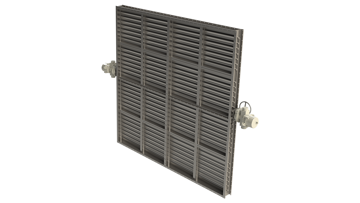
浩盾 FDL 防火阀是具有型式认证的 A0(A60) 级防火阀,广泛适用于钻井平台,船舶和舰艇上的通风系统。


概述
需要注意的重要事项:
给 Halton 船舶、能源和基础设施客户的重要信息
我们特此通知您,我们已决定逐步停止生产 FDL 防火阀。
请注意,如果产品已安装在船上,则需要有效的型式认可证书。FDL防火阀的证书有效期如下:
- MED (BV),2026 年 1 月 26 日到期
- 英国劳氏(Lloyd’s Register),2025年7月20日到期
- DNV,2026年2月7日到期
- ABS,2026年9月2日到期
************************
- 获得各类著名船级社的型式认可:A0 级无绝缘,A15-A60 适当绝缘
- 可进行 ATEX 认证。通过冲击测试。
- 焊连的外框和组装的风叶可选材质为喷漆、镀锌或不锈钢。免维护的不锈钢轴套和转轴。
- 不带密封的风叶
- 标称熔断温度为 50 ºC、74 ºC 或 100 ºC。可选其它温度。
- 可以安装在任何位置
- 自动、气动或手动执行器可选
- 阀门结构可适应的最大管道压力为 5000 Pa,最大空气流速为 15 m/s。如果管道压力过高,请联系浩盾船舶寻求最佳解决方案。
- 特定风闸可提供SIL 2安全认证
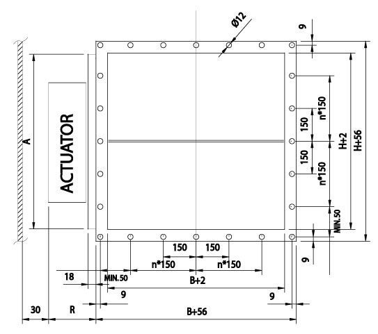
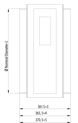
Dimensions
The Halton FDL fire dampers are manufactured according to international standards for both rectangular (width B 100-1300 mm and height H 100-1200 mm, 1 mm division) and circular ducts (Ø100-1250 mm). Modular constructions are available for bigger sizes. Non-standard dimensions and flange drilling are available on request.
Standard flange width 27 mm. Flanges and drilling also available according to ISO 15138 standards.
Blades are made of two sheets, each of them being 1 mm thick (sandwich design).
Modular construction sizes up to 2660×2460 mm.
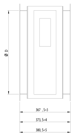
Frame material thickness 3 mm or 3-5 mm according to SOLAS.
Frame thickness according to SOLAS
| DIMENSIONS | S |
| If B or H > 100, but < 449 | 3 |
| If B or H > 450 but < 649 | 4 |
| If B or H > 650 | 5 |
Frame thickness according to SOLAS, Edition Dec. 2015
| DIMENSIONS | S |
| If A < 0.075 m2 | 3 |
| If A > 0.075 and A < 0.45 m2 | 4 |
| If A > 0.45 m2 | 5 |
Actuator effect in dimensions
| ACTUATOR | R | A | |
| Electrical (EL) | BF230, BF24, BF120 | 100 | H<300 = 300, H>300 =H |
| Pneumatic (PNR) | Pneumatic rotating actuator AT100 | 170 | H<300 = 300, H>300 =H |
| Pneumatic (PNR) | Pneumatic rotating actuator AT200 | 190 | H<350 = 350, H>350 =H |
| Spring (SP) | Spring | 140 | H |
The above table contains only some examples of actuators and their effect on dimensions.
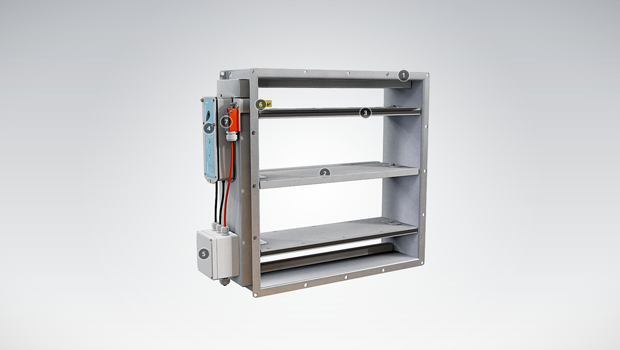
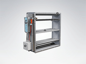
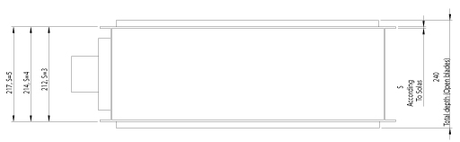
FDL, general drawings
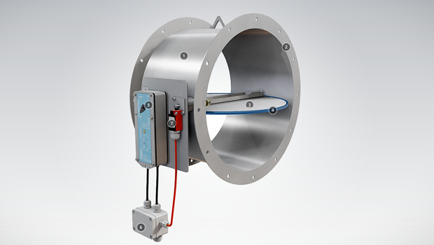
With circular connections
FDL, top
FDL circular, with connection flanges
| DAMPER HEIGHT H | TOTAL DEPTH WITH BLADES OPEN |
| < 250 mm | 212 mm |
| > 250 mm <300 mm | 250 mm |
| > 300 mm <350 mm | 212 mm |
| > 350 mm | 240mm |
Material and Finishing
| PART | MATERIAL | FINISHING |
| Frame | Carbon steel | Painted or galvanized |
| Frame | Stainless steel EN 1.4301 (AISI304), EN 1.4404 (AISI316L), EN 1.4432 (AISI316L) | – |
| Blades | Steel | Galvanized |
| Blades | Stainless steel EN 1.4301 (AISI304), EN 1.4404 (AISI316L), EN 1.4432 (AISI316L) | – |
| Maintenance-free bearings |
Stainless steel EN 1.4404 (AISI316L) | – |
| Shafts | Stainless steel EN 1.4404 (AISI316L) | – |
Standard frame material thickness 3-5 mm according to SOLAS.
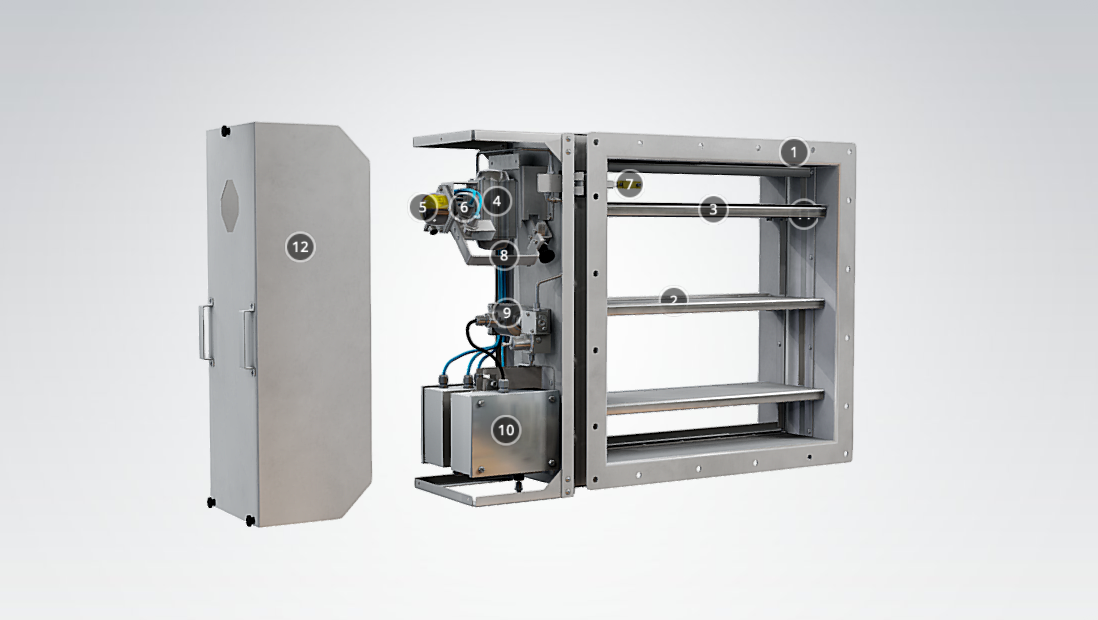
Product Models and Accessories
Halton FDL is available with following actuators:
- FDL-EL: Electrical spring return motor; standard actuators being 24 V or 230 V or 120 V. The motor contains built-in open-closed limit switches. Separate junction box included in the EL-model. A wide range of Ex actuators available, including a one second closing time function as an option.
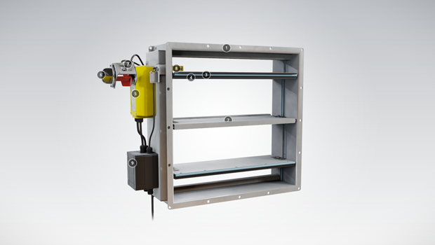
- FDL-PNR: Pneumatic rotating actuator.
- FDL-SP: Manual spring-actuated damper with fusible link.
DOT: manual override function available for PNR and EL models.
HSO: Halton Smart Override function for HVAC damper black-start available for PNR and EL models. With automatic reset function when power and/or pneumatic air supply is reinstated.
A wide range of accessories available.
Operation Principles
In the event of a temperature rise in ductwork:
- FDL-EL: fusible link releases and cuts off operating voltage to the spring return motor, allowing the spring to close the damper blades. The fire damper opens automatically when the fuse has been changed and the operating voltage to the motor is re-established.
- FDL-PNR: fusible link releases and cuts off operating pressure to the spring return actuator, allowing springs to close the damper blades. The fire damper opens automatically when the fuse has been changed and the pneumatic air supply is re-established.
- FDL-SP: fusible link releases allowing the spring to close the damper blades. When the fuse has been changed, the fire damper must be reset into open position manually.
Weights
Weight of standard Halton Marine FDL dampers without an actuator (kg)
| H/HEIGHT (mm) |
B / WIDTH (mm) | ||||||||||||
| 100 | 200 | 300 | 400 | 500 | 600 | 700 | 800 | 900 | 1000 | 1100 | 1200 | 1300 | |
| 100 | 5 (5) | 7 (7) | 9 (9) | 10 (10) | 12 (13) | 14 (15) | 15 (22) | 17 (25) | 19 (27) | 20 (30) | 22 (32) | 24 (35) | 25 (37) |
| 200 | 7 (7) | 9 (9) | 11 (11) | 12 (12) | 14 (16) | 16 (18) | 18 (26) | 20 (28) | 22 (31) | 23 (34) | 25 (36) | 27 (39) | 29 (41) |
| 300 | 9 (9) | 11 (11) | 13 (13) | 15 (15) | 17 (19) | 19 (21) | 21 (30) | 23 (32) | 25 (35) | 27 (38) | 29 (41) | 31 (43) | 33 (46) |
| 400 | 11 (11) | 13 (13) | 15 (15) | 17 (17) | 20 (22) | 22 (24) | 24 (33) | 26 (36) | 28 (39) | 30 (42) | 32 (45) | 34 (48) | 37 (51) |
| 500 | 13 (16) | 16 (19) | 18 (22) | 21 (25) | 23 (27) | 25 (30) | 28 (38) | 30 (41) | 32 (44) | 35 (47) | 37 (50) | 39 (54) | 42 (57) |
| 600 | 15 (18) | 18 (21) | 20 (24) | 23 (27) | 25 (30) | 28 (33) | 30 (41) | 33 (45) | 35 (48) | 38 (51) | 40 (55) | 43 (58) | 46 (61) |
| 700 | 18 (25) | 21 (28) | 23 (32) | 26 (35) | 29 (39) | 32 (42) | 34 (46) | 37 (50) | 40 (53) | 42 (57) | 45 (60) | 48 (64) | 51 (67) |
| 800 | 20 (27) | 23 (31) | 25 (35) | 28 (38) | 31 (42) | 34 (46) | 37 (50) | 40 (53) | 43 (57) | 46 (61) | 49 (64) | 51 (68) | 54 (72) |
| 900 | 22 (31) | 25 (35) | 28 (39) | 32 (42) | 35 (46) | 38 (50) | 41 (54) | 44 (58) | 47 (62) | 50 (66) | 53 (70) | 56 (74) | 59 (78) |
| 1000 | 24 (33) | 27 (37) | 31 (41) | 34 (45) | 37 (50) | 40 (54) | 44 (58) | 47 (62) | 50 (66) | 53 (70) | 57 (74) | 60 (78) | 63 (82) |
| 1100 | 26 (36) | 30 (41) | 33 (45) | 37 (49) | 40 (54) | 44 (58) | 47 (62) | 51 (67) | 54 (71) | 58 (75) | 61 (79) | 65 (84) | 68 (88) |
| 1200 | 28 (39) | 32 (44) | 36 (48) | 39 (52) | 43 (57) | 46 (61) | 50 (66) | 54 (70) | 57 (75) | 61 (79) | 65 (84) | 68 (88) | 72 (92) |
| D2 ØD | WEIGHT |
| (mm) | kg |
| 100 | 8 (8) |
| 125 | 8 (8) |
| 160 | 12 (12) |
| 200 | 13 (13) |
| 250 | 19 (19) |
| 315 | 20 (20) |
| 400 | 27 (27) |
| 500 | 35 (43) |
| 630 | 46 (62) |
| 800 | 62 (89) |
| 1000 | 83 (118) |
| 1250 | 113 (162) |
(Frame thickness according to SOLAS)
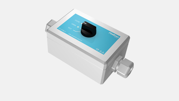
Examples of actuator weights: FDL-EL BF230 +3,2 kg, BFN +1,4 kg, ExMax /Redmax +3,5 kg, CSQP +3 kg. FDL-PNR AT100 +2,1 kg, AT100 as AISI316 4,4 kg, AT200 +3,2kg, AT200 as AISI316 +6,2 kg, FDL-SP +1 kg. Control enclosure +4 kg.
Installation
Installation and maintenance instructions are with each fire damper delivery. Copies of Operation and Maintenance manuals are available from Halton Marine Sales offices and distributors.
Product Code
| (S)=Shape of Connection | |||||||
| (A) Circular (D1) | |||||||
| (C ) Circular (D2) | |||||||
| (R) Rectangular | |||||||
| (W)=Width | |||||||
| 100-1300 | |||||||
| (H)=Height | |||||||
| 100-1200 | |||||||
| (D)=Diameter | |||||||
| 100-1250 | |||||||
| (FA)=Fire Approval | |||||||
| (C1) ABS American Bureau of Shipping | |||||||
| (C2) MED Marine Equipment Directive | |||||||
| (C4) DNV Det Norske Veritas | |||||||
| (C5) BV Bureau Veritas | |||||||
| (C6) GL Germanischer Lloyds | |||||||
| (C7) USCG United States Cost Guard | |||||||
| (C9) RMRS Russian Maritime Register | |||||||
| (SF)=Flange Option | |||||||
| (H0) Connection flange in circular connections | |||||||
| (H1) Connection + loose flange in circular connections | |||||||
| (HA) Flanges (2 sides) | |||||||
| (HB) Counter flanges (2 sides) | |||||||
| (HC) Counter flange (1 side) | |||||||
| (NA) Not Assigned (circular connection) | |||||||
| (FS)=Frame dimensioning | |||||||
| (HS) Halton Standard dimensioning | |||||||
| (S0) SOLAS dimensioning | |||||||
| (MA)=Material | |||||||
| (AS) Stainless steel (1.0) EN1.4404 | |||||||
| (CS) Carbon steel (1.0) | |||||||
| (LS) Stainless steel (1.0) EN1.4432 | |||||||
| (SS) Stainless steel (1.0) EN1.4301 | |||||||
| (FM)=Frame Material | |||||||
| (A3) Stainless steel (3.0) EN1.4404 | |||||||
| (A4) Stainless steel (4.0) EN1.4404 | |||||||
| (A5) Stainless steel (5.0) EN1.4404 | |||||||
| (C3) Carbon steel (3.0) EN1.4404 | |||||||
| (C4) Carbon steel (4.0) EN1.4404 | |||||||
| (C5) Carbon steel (5.0) EN1.4404 | |||||||
| (L3) Stainless steel (3.0) EN1.4432 | |||||||
| (L4) Stainless steel (4.0) EN1.4432 | |||||||
| (L5) Stainless steel (5.0) EN1.4432 | |||||||
| (S3) Stainless steel (3.0) EN1.4301 | |||||||
| (S4) Stainless steel (4.0) EN1.4301 | |||||||
| (S5) Stainless steel (5.0) EN1.4301 | |||||||
| (FI)=Finishing | |||||||
| (HG) Hot galvanized | |||||||
| (NA) Not Assigned (acid treatment) | |||||||
| (PN) Painting | |||||||
| (RE)=Actuator | |||||||
| (E1) Electric BF24-2-HL | |||||||
| (E3) Electric BF230-2-HL | |||||||
| (E7) Electric BF120-HL | |||||||
| (K0) Electric BFN24.1 | |||||||
| (K1) Electric BFN24-T.1 | |||||||
| (K2) Electric BFN230.1 | |||||||
| (K3) Electric BFN230-T.1 | |||||||
| (I1) InMax 15-SF | |||||||
| (P0) Pneumatic – Air Torque, AT101, Aluminium | |||||||
| (P1) Pneumatic Lin Roder 245N | |||||||
| (P2) Pneumatic Lin Roder 300N | |||||||
| (P3) Pneumatic – Air Torque, AT104, AISI316 | |||||||
| (Q1) Pneumatic – Air Torque, AT201, Aluminium | |||||||
| (Q2) Pneumatic – Air Torque, AT204, AISI316 | |||||||
| (R2) Ex-proofed RedMax 15-SF | |||||||
| (S1) Spring | |||||||
| (T1) Electric BF24-T-2.1HL | |||||||
| (T3) Electric BF230-T-2.1HL | |||||||
| (Z2) Ex-proofed ExMax 15-SF | |||||||
| (Z3) Ex-proofed ExMax 5-10SF | |||||||
| (C1) Electric CSQP-05A1E 24V | |||||||
| (C2) Electric CSQP-05A2E 120/230V | |||||||
| (C3) Electric CSQP-10A1E 24V | |||||||
| (C4) Electric CSQP-10A2E 120/230V | |||||||
| (C5) Electric CSQP-15A1E 24V | |||||||
| (C6) Electric CSQP-14A2E 120/230V | |||||||
| (FU)=Fuse | |||||||
| 144 °C | |||||||
| 100 °C | |||||||
| 95 °C | |||||||
| 74 °C | |||||||
| 72 °C | |||||||
| 70 °C | |||||||
| 65 °C | |||||||
| 50 °C | |||||||
| (AC)=Accessories | |||||||
| (BC) Belimo Casing | |||||||
| (E1) Junction box IP66/67 (Plastic) (Ensto) | |||||||
| (E2) EX junction box IP66/T6 (GRP) (Ensto) | |||||||
| (E4) Connectors (FD) (Wieland & Hensel)) | |||||||
| (L1) Limit switch 1 pcs IP66 (Plastic) (Bernstein) | |||||||
| (L2) Limit switch 2 pcs IP66 (Plastic) (Bernstein) | |||||||
| (L3) EX Limit switch 1 pcs (Plastic) (Bartec) | |||||||
| (L4) EX Limit switch 2 pcs (Plastic) (Bartec) | |||||||
| (M1) Solenoid valve 24 VDC (Aluminium) (SMC) | |||||||
| (M2) Solenoid valve 230 VAC (Aluminium) (SMC) | |||||||
| (M3) EX solenoid valve 24 VDC (Brass) (Norgren) | |||||||
| (M4) EX solenoid valve 230 VAC (SS) (Norgren) | |||||||
| (P1) Pneumatic valve manual (Aluminum) (SMC) | |||||||
| (S3) SN2 auxiliary switch (Belimo) | |||||||
| Stainless steel tubing (AISI316) ( Halton) | |||||||
| (ED) DOT handle (manual overdrive) (Steel) (Halton) | |||||||
| Code example | |||||||
| FD3/R-1300-1200,FA=C1,SF=HA,FS=SO,MA=CS,FM=C5,FI=HG,RE=Z2,FU=50,ZT=N,AC=E2 | |||||||
Downloads
-
FDL – A0(A60) Fire damper
Data
en
-
FDL – A0(A60) Palopelti
Data
fi
-
FDL – A0(A60) Fire damper
Data
fr
-
FDL A0(A60) 防火阀
Data
cn
-
Halton FDL datasheet 2024
Data
English -
ABS Certificate for Halton FDL
Data
English -
ATEX Certificare for FDB2, FEX, FDL, FDO, FDA
Data
English -
DNV GL Certificate for Halton FDL
Data
English -
LR Certificate of Fire Approval for Halton FDL
Data
English -
MED BV Certificate for FDL
Data
English -
RMRS Certificate for Halton FDL
Data
Русский (ru) -
TR CU – SAFE Certificate for Halton FDB2, FDL, FEX, UTG, UTX, UTP, UTN, UTT, BLD, BRD
Data
Русский (ru) -
Halton Marine Oy MED Quality System Module D Certificate
Data
English -
SIL 2 Safety Assessment Certificate
Data
English