Product / KW3
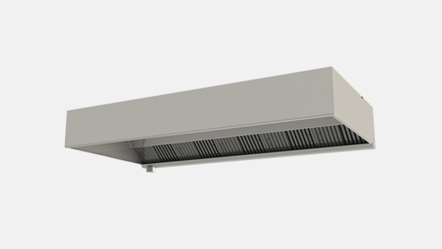
KW3 厨房水洗烟罩
Halton KW3 是一款采用捕获射流 3 技术的厨房水洗烟罩,广泛适用于船舶和钻井平台。能够大幅节约所需的排气量。


概览
- Halton捕获射流 TM 3 技术可减少所需的排气量,提高烟罩捕获和覆盖效率,同时降低能耗
- 该项设计符合 USPHS 要求
- 自动定期清洗排气腔和 KSA 油脂过滤器(如适用还可清洗紫外线管)
- 维护需求较低,可减少人员清洗过滤器的工作量
- 十分利于环境卫生
- 防止油脂沉积物堆积造成严重的火灾隐患
- 高效油脂过滤采用 *UL 级的Halton KSA 多级旋风过滤器
- 进气和排气以及 T.A.B. TM 流量测量支管的标配包括照明设备和平衡阀,可用来精确有效地平衡气流,并实现高效调试
- 不锈钢焊接结构
Dimensions and Weight
KW3 general drawings
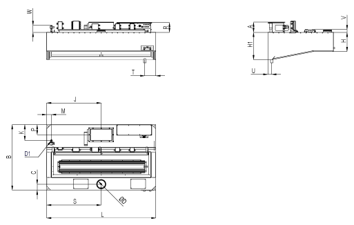
| KW3 DIMENSIONS | |||
| A | 195 | L | 1000-3000 |
| B | 1100-1900 | M | 87 |
| C | 110 | P | 185 |
| D | 100-200 | S | 1/2L |
| D1 | 3/4” | T | 100-200 |
| H | 350 | U | 70 |
| H1 | 500 | R | 185 |
| J | 1/2L | V | max 50 |
| K | 291 | W | ~130 |
Note: Maintenance / light fixture hatch is as big as the construction allows.
Note: Minimum length with UV-light technology is 1200 mm.
Material
| PART | MATERIAL | THICKNESS | NOTE |
| Front and side walls | Stainless steel EN 1.4301 (AISI304) | 1,25 mm | Option: EN 1.4404 (AISI316L) |
| Main body | Stainless steel EN 1.4301 (AISI304) | 1,25 mm | Option: EN 1.4404 (AISI316L) |
| Light fixture | Painted steel | – | |
| Wash piping | Stainless steel, brass | – | |
| Cables | Halogen free | – |
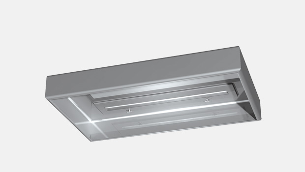
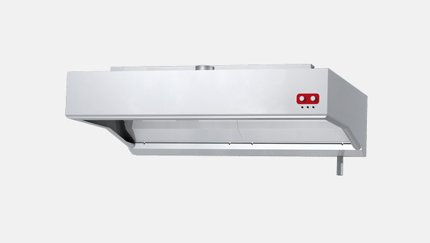
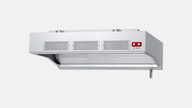
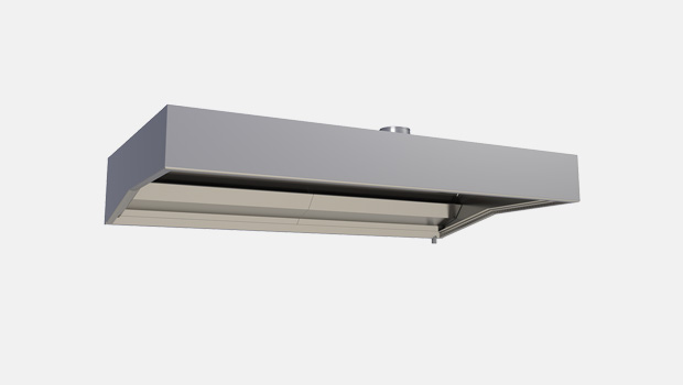
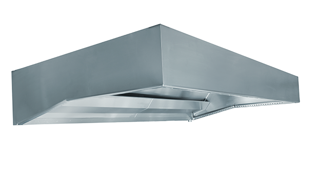
Construction
The KW3 hood comprises a Capture Jet™ air supply module, a light fixture, adjustment dampers, airflow measurement taps and KSA grease filters. All parts of the hood are manufactured from polished stainless steel EN 1.4301 (AISI304). The joints at the lower edges of the device are watertight. A drain pipe connection is fitted into the exhaust plenum in order to enable removal of the grease and dirt extracted by the KSA multi-cyclone filters and to drain the washing water. The Capture Jet supply plenum is thermally insulated through the use of mineral wool material to prevent condensation on the inner face above the cooking equipment.
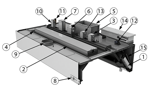
PARTS
1 KSA grease filters
2 Lighting fixture
3 Lighting fixture power supply junction box
4 Maintenance hatch
5 Exhaust air connection, fire damper or shut-off damper* (available as an option) and adjustment damper
6 Fire damper junction box
7 Actuator power and fuse info junction box
8 Damper switch and indication (available as an option)
9 Capture air connection and adjustment damper
10 Water wash piping connection R3/4” (G3/4” solenoid valve as an option)
11 Washing solenoid valve junction box
12 UV system, available as an option
13 UV power supply junction box, available as an option
14 UV control junction box, available as an option (location may vary)
15 Mesh filter, available as an option
*If fire or shut-off damper is located at the duct, Halton suggests two default solutions for duct connection:
- Eurovent-collar with flange
- Welded L-collar
Eurovent-collar with flange
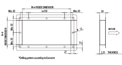
Welded L-collar

Weights of standard KW3 hoods (kg)
| B/L | 1200 | 1600 | 2000 | 2500 | 3000 |
| 1100 | 107 | 130 | 156 | 182 | 211 |
| 1300 | 112 | 137 | 163 | 191 | 220 |
| 1500 | 118 | 144 | 171 | 199 | 230 |
| 1700 | 124 | 150 | 178 | 208 | 240 |
| 1900 | 130 | 158 | 189 | 218 | 250 |
The above table represents an indication of different size of average KW3 hoods. Weight does not include a fire damper.
Weights of standard KW3 hoods with UV-lights (kg)
| B/L | 1200 | 1600 | 2000 | 2500 | 3000 |
| 1100 | 128 | 155 | 183 | 215 | 249 |
| 1300 | 133 | 162 | 191 | 223 | 258 |
| 1500 | 139 | 169 | 198 | 232 | 268 |
| 1700 | 145 | 175 | 206 | 240 | 278 |
| 1900 | 151 | 183 | 217 | 251 | 288 |
The above table represents an indication of different size of average KW3 hoods with UV-light technology. Weight does not include a fire damper.
Product Options and Accessories
- Non-standard spigots: choice of size and position
- UV-light filtration – a combination of KSA filter, mesh filter and ultraviolet-light technology
- EN 1.4404 (AISI316L) construction
- Modulating fire damper manufactured of EN 1.4301 (AISI304) or EN 1.4404 (AISI316L) or shut-off damper in exhaust connection
- Wet chemical fire suppression system
- M.A.R.V.E.L. demand-based ventilation system
Function
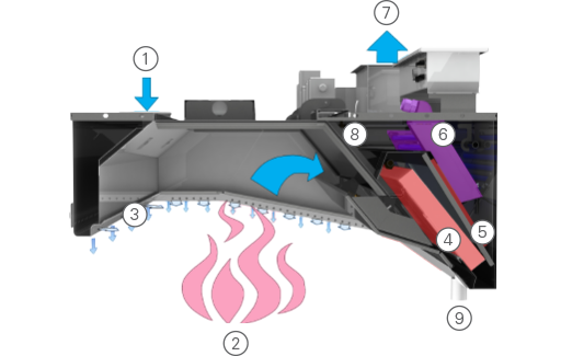
- Supply air enters the Capture JetTM plenum.
- Contaminated air and heat rises from the cooking appliances.
- Contaminated air is directed into the hood from three different sides by Halton patented Capture JetTM technology.
- KSA multi-cyclone filters remove grease and contaminants from the air stream with the aid of centrifugal effect. According to independent laboratory tests KSA is the most efficient mechanical grease filter on the market.
- Mesh filter balances the airflow inside exhaust plenum and apply more filtration to the air. Together with KSA filter this doubles filtration efficiency. Mesh filter is available as an option.
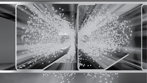
- Based on Halton’s patented highly efficiency Capture JetTM solution and advanced mechanical KSA filter technology, the UV-light technology with scheduled maintenance keeps the plenum and duct virtually grease-free and mitigates the cooking odor and emissions. The grease vapor and effluents that are not collected by high-efficiency filters pass over the lamps. This causes a chemical reaction that destroys the grease and converts it into carbon dioxide and water vapor. The chemical action carries over into the duct and helps keep the duct and exhaust fan clean.UV-filtration is available as an option.
- Cleaned exhaust air contains small amounts of Ozone which further cleans the ducts downstream. All excess Ozone converts back into Oxygen.
- At scheduled times the washing control cabinet stops the hood operation and begins a washing cycle. Hot water with mild detergent is pumped into the hood spray nozzles, washing the essential parts of the exhaust plenum including UV-lights and filters. Due to improved washing result, fire or shut-off damper of the hood has to be modulated to minimal airflow during washing cycle.
- The waste from the washing cycle is drained from the hood via the drain connection.
Recommended exhaust airflow for KW3
| NUMBER OF KSA FILTERS | ||||
| MINIMUM l/s | MAXIMUM l/s | MINIMUM m3/h | MAXIMUM m3/h | |
| 1 | 130 | 201 | 468 | 724 |
| 2 | 259 | 402 | 932 | 1447 |
| 3 | 389 | 602 | 1400 | 2167 |
| 4 | 518 | 803 | 1865 | 2891 |
| 5 | 648 | 1004 | 2333 | 3614 |
| 6 | 778 | 1205 | 2801 | 4338 |
Note: KSA filter size 500x330x50 mm
Specification
Suggested specification
The water wash galley hoods shall be constructed from stainless steel EN 1.4301 (AISI304). The galley hoods shall be supplied complete with outer casing / main body, capture jet plenum, airflow measurement taps, supply and exhaust air spigot connections with adjustment damper, maintenance hatch, light fixture, capture air jet, grease filters, drain connection, automatic washing system controlled by separate control cabinet with interfaces to ships safety systems. Classified fire damper in each exhaust connection. The manufacture of all galley hoods shall be controlled by ISO 3834-2:2005, ISO 9001, 14001 and OHSAS 18001 standards. The design of hoods shall follow USPHS guidelines.
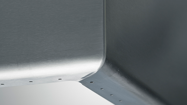
Construction
All parts shall be constructed of stainless steel sheet EN 1.4301 (AISI304) (thickness 1.25 mm) with a polished finish. The inside corners of the hood are rounded for easy cleanability according to USPHS guidelines. The joints at the lower edges of the device are welded watertight. All visible screws are thumb screw type. The hood is equipped with a drain connection for removing the dirty water. There is a maintenance hatch in each hood for easy access above the hood.
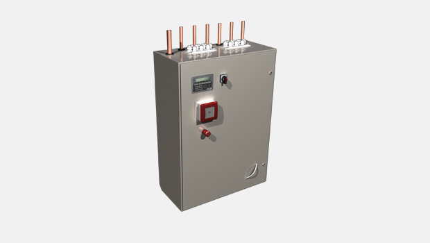
Washing module
Grease filters shall have an automatic washing cycle utilising warm water and detergent via nozzles. The mixing of the detergent occurs within a separate control cabinet. The wastewater shall be removed from the hood by a direct drain connection. The casing of the control cabinet shall be constructed of stainless steel sheet EN 1.4301 (AISI304).
Capture Jet™ plenum
The Capture JetTM plenum shall be insulated with sealed mineral wool. Plenum can be accessed through a maintenance hatch(es).
Capture Jet™ system
The hood shall be designed with Capture JetTM technology to reduce the exhaust airflow rate required and increase the capture and containment efficiencies of the hood, while reducing energy use.
Airflow measurement taps
Measurement taps shall be located on top of the hood for capture air and exhaust air measurement.
Demand based filtration
Halton KSA filter
- Minimisation of grease deposits in the ducts
- Enhanced hygiene and safety
The KSA grease filters shall be constructed of stainless steel EN 1.4301 (AISI304). The grease filters shall be supplied in modular size of 500x330x50 mm and shall be removable via two folding handles. The grease filters shall have a honeycomb design in order to allow high grease filtration efficiency with the aid of centrifugal effect in filter honeycombs.
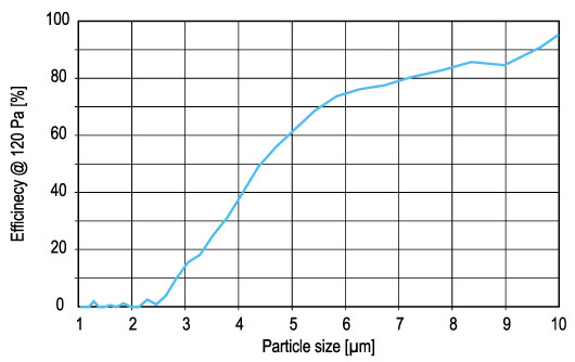
Mechanical filtration is recommended to be used in hoods with low utilization rate and cooking process producing mainly large grease particles (> 8 microns), e.g. food prepared with gas fryers, griddles and broilers (source ASHRAE).
UV-light filtration
Halton’s UV-light technology is the most efficient solution for hoods with medium to high utilization rate and cooking processes producing all sizes of grease particles, e.g. food prepared with electric ranges, griddles and all type of broilers.
In the UV-light concept, most of the grease particles are first filtered with mechanical filtration (type KSA). The mesh filter behind the KSA spreads the airflow and the remaining grease particles inside the hood chamber. This increases filtration efficiency up to 50% with grease particles sizes between 5-8 microns. Based on Halton’s patented highly efficiency Capture JetTM solution and advanced mechanical KSA filter technology, the UV-light technology with scheduled maintenance keeps the plenum and duct virtually grease-free and mitigates the cooking odor and emissions. The grease vapor and effluents that are not collected by high-efficiency filters pass over the lamps. This causes a chemical reaction that destroys the grease and converts it into carbon dioxide and water vapor. The chemical action carries over into the duct and helps keep the duct and exhaust fan clean.
Duct connections
The duct connections and adjustment dampers for supply and exhaust air shall be constructed from stainless steel.The dampers shall be adjustable.
Light fixtures
Each hood shall be delivered with a fluorescent light fixtures or energy efficient LED light fixtures providing approx. an average illuminance of 500 lux at the work surfaces of the cooking appliances. The light fixtures shall be suitable for a single-phase 230-VAC power supply and shall be manufactured to be of protection class IP67. The ballast and capacitor shall be located within the light Frame. The core electric cables connecting the light fixture to the junction box shall be provided. The light fixture shall be installed on a hinged maintenance hatch, allowing access to the hood roof.
Fluorescent light fixture sizes
| HOOD DIMENSION | LENGTH | WIDTH |
| L < 1400 mm, 2×24 W | 720 mm | 220 mm |
| L > 1400 mm, < 2000 mm, 2×39 W | 1020 mm | 220 mm |
| L > 2000 mm, 2×49 W | 1620 mm | 220 mm |
LED light fixture sizes
| HOOD DIMENSION | LENGTH | WIDTH |
| L < 1400 mm, 1×28 W | 720 mm | 175 mm |
| L > 1400 mm, < 2000 mm, 1×42 W | 1020 mm | 175 mm |
| L > 2000 mm, 1×69 W | 1620 mm | 175 mm |
Maintenance hatch
Each hood shall be provided with a maintenance hatch made of stainless steel EN 1.4301 (AISI304) with a shock-resistant plastic window. The heat tolerance of the window shall be up to +115 °C. The hatch shall be easily opened and closed.
The maintenance / light fixture hatch is as big as the construction allows.
Airflow measurement
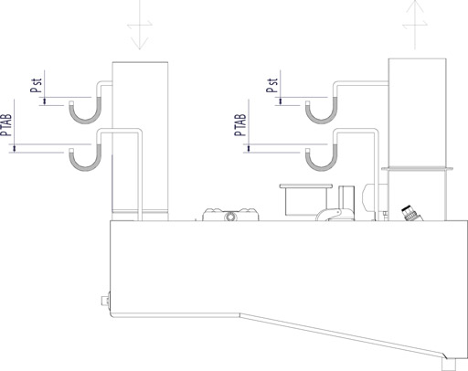
∆Pst = Static pressure loss
∆PTAB = TAB pressure for airflow rate measurement
70, 100 = Damper opening in %
Product Code
| (S)=Model | |||||||||||||
| (N) With Capture Jet | |||||||||||||
| (L)=Length | |||||||||||||
| 1100-3000 mm (with UV 1200-3000 mm) | |||||||||||||
| For UV-lights more space is needed | |||||||||||||
| (W)=Width | |||||||||||||
| 1100-1900 mm | |||||||||||||
| (H)=Height of front end | |||||||||||||
| 350-400 mm (without water wash 350-450 mm) | |||||||||||||
| The height of back end is 500 mm | |||||||||||||
| (WF)=Washing Function | |||||||||||||
| (A) Type GE CCW | |||||||||||||
| (B) Type FI WR (locked – not available) | |||||||||||||
| (N) No | |||||||||||||
| (UV)=UV-light filtration | |||||||||||||
| (Y) Yes | |||||||||||||
| (N) No | |||||||||||||
| (FD)=Fire damper control | |||||||||||||
| (Y) Yes | |||||||||||||
| (N) No | |||||||||||||
| (MV)=Marvel | |||||||||||||
| (N) No | |||||||||||||
| (A) 1 sensor | |||||||||||||
| (B) 2 sensors | |||||||||||||
| (C) 3 sensors | |||||||||||||
| (D) 4 sensors | |||||||||||||
| (UB)=UV or Marvel Box | |||||||||||||
| (A) UV-box ALU | |||||||||||||
| (B) UV-box SS | |||||||||||||
| (C) Marvel-box PL | |||||||||||||
| (N) No | |||||||||||||
| (MA)=Material | |||||||||||||
| (SS) Stainless steel EN1.4301 | |||||||||||||
| (AS) Stainless steel EN1.4404 | |||||||||||||
| (DS)=Diameter of supply connection | |||||||||||||
| 100 | |||||||||||||
| 125 | |||||||||||||
| 160 | |||||||||||||
| 180 | |||||||||||||
| 200 | |||||||||||||
| (LF)=Light fixture | |||||||||||||
| (A) Type SLR | |||||||||||||
| (B) Type LED SLV | |||||||||||||
| (FK)=Fire suppression system | |||||||||||||
| (N) No | |||||||||||||
| (1) 1 pcs | |||||||||||||
| (2) 2 pcs | |||||||||||||
| (3) 3 pcs | |||||||||||||
| (AC)=Accessories | |||||||||||||
| (L3) Three Fire Damper LED indicators | |||||||||||||
| (L2) Two Fire Damper LED indicators | |||||||||||||
| (S2) Fire Damper and LED open/close test switches | |||||||||||||
| (S1) Fire Damper open/close switch | |||||||||||||
| (BL) Capture Jet fan with potentiometer | |||||||||||||
| (HE) Ceiling condensation removal heating | |||||||||||||
| Code example | |||||||||||||
| KW31/N-3000-1900-400,WF=A,UV=Y,FD=Y,MV=D,UB=A,MA=SS,DS=200,LF=B,FK=1,ZT=Y,AC=L2,S1,BL | |||||||||||||
Downloads
-
KW3 – Galley Water Wash Hood
Data
en
-
KW3 – Vesipesutekniikalla varustettu laivakeittiön huuva
Data
fi
-
KW3 – Hotte de cuisine Water Wash pour navires
Data
fr
-
KWH – Schiffsküchen-Wasserspülhaube
Data
de
-
KW3 厨房水洗烟罩
Data
cn
-
Halton KW3 datasheet 2024
Data
English -
Halton KW3 datasheet 2022 – Italian
Data
Italian -
Halton Marine Galley Ventilation FAQ
Data
English -
Halton UV-Light Technology datasheet 2024
Data
English -
Halton UV-Light Technology datasheet 2022 – Italian
Data
Italian