Product / FDB2
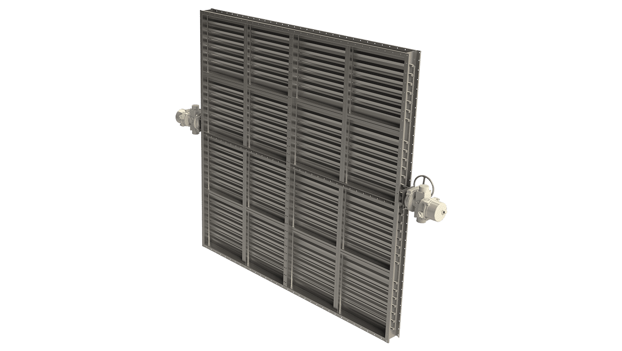
FDB2用于高要求应用的A0(A60)防火隔烟风闸
Halton FDB2 防火隔烟阀是世界上最畅销的船舶用防火隔烟阀。


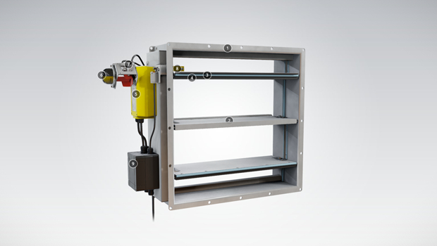
概述
- 获得各类著名船级社的型式认可:A0 级无绝缘,A15-A60 适当绝缘
- 通过ATEX/IECEx认证
- 通过冲击测试。
- 风叶包含硅胶(温度可达 300 ºC),防止正常环境下泄漏,以及热膨胀石墨密封条(150 ºC 以上有效),
在起火状况下使风闸紧密度可增加 50%。闭合的阀符合防泄漏等级 3 的要求 (EN1751:1998)。测试尺寸为 1000×1000 mm。 - 标称熔断温度为 50 ºC、74 ºC 或 100 ºC。可选其它
温度。 - 专利双层风叶结构,重量轻巧
- 自动、气动或手动执行器可选
- 阀门结构可适应的最大管道压力为 5000 Pa,最大
空气流速为 15 m/s - 特定风闸可提供SIL 2安全认证
尺寸
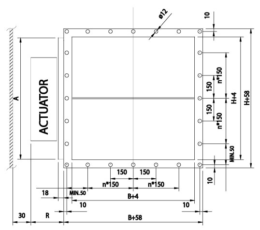
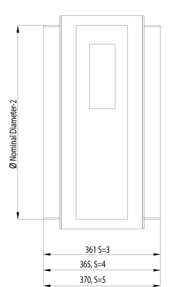
FDB2 防火风闸符合国际标准,适用于矩形管道(宽度 B 100-1200 mm,高度 H 100-1600 mm,1 mm间距)和圆形管道(直径 100-1250 mm)。模块化结构可用于更大的尺寸。可根据要求提供非标准尺寸和法兰钻孔。标准法兰宽度 27 mm。也可根据 ISO 15138 标准提供法兰和钻孔。根据 SOLAS 标准,框架厚度为 3 mm或 3-5 mm。也可根据要求提供 6、8 和 10 mm的框架厚度。桨叶由两片桨叶组成,每片桨叶厚 1 mm(三明治设计)。
框架厚度符合 SOLAS 标准
| 尺寸 | S |
| If B or H > 100, but < 449 | 3 |
| If B or H > 450 but < 649 | 4 |
| If B or H > 650 | 5 |
框架厚度符合 SOLAS 标准,2015 年 12 月版
| 尺寸 | S |
| If A < 0.075 m2 | 3 |
| If A > 0.075 and A < 0.45 m2 | 4 |
| If A > 0.45 m2 | 5 |
执行器适用尺寸
| 执行器 | R | A | |
| 电动 (EL) | BF230, BF24, BF120 | 100 | H<300 = 300, H>300 =H |
| 气动 (PNR) | Pneumatic rotating actuator AT100 | 170 | H<300 = 300, H>300 =H |
| 气动 (PNR) | Pneumatic rotating actuator AT200 | 190 | H<350 = 350, H>350 =H |
| 手动 (SP) | Spring | 140 | H |
上表仅列举了一些执行器及其适用尺寸。
FDB2总图
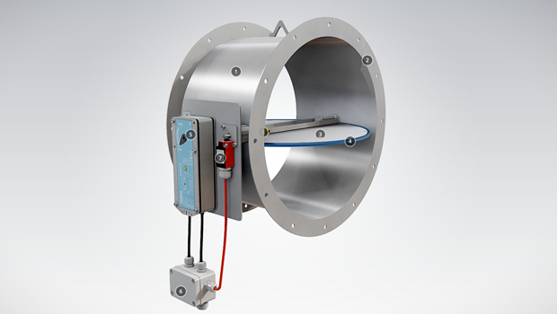
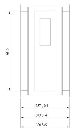
FDB2 圆形连接
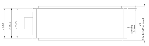
FDB2 总图,顶视图
FDB2 圆形管道连接图
| 风闸高度 | 叶片打开时的总深度 |
| < 250 mm | 210 mm |
| > 250 mm < 300 mm | 250 mm |
| > 300 mm < 349 mm | 210 mm |
| > 350 mm | 240 mm |
材料和表面处理
| 部件 | 材料 | 表面处理 |
| 外框 | 碳钢 | 喷漆或镀锌 |
| 外框 | 不锈钢 EN 1.4301 (AISI304), EN 1.4404 (AISI316L), EN 1.4432 (AISI316L) | – |
| 风叶 | 钢 | 镀锌 |
| 风叶 | 不锈钢 EN 1.4301 (AISI304), EN 1.4404 (AISI316L), EN 1.4432 (AISI316L) | – |
| 免维护轴套 | 不锈钢 EN 1.4404 (AISI316L) | – |
| 转轴 | 不锈钢 EN 1.4404 (AISI316L) | – |
产品模型和附件
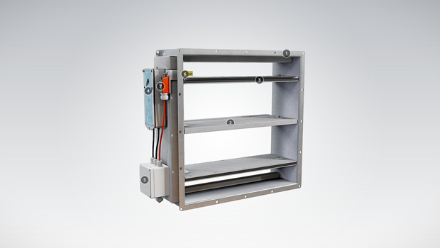
浩盾FDB2可配备以下执行器:
- FDB2-EL: 电动弹簧复位马达;标准执行器电压为 24 V、230 V 或 120 V。EL 型包括单独的接线盒。有多种防爆执行器可供选择,包括可选的一秒关闭功能。
- FDB2-PNR: 气动旋转执行器
- FDB2-SP: 带熔断片的手动弹簧式执行器阀
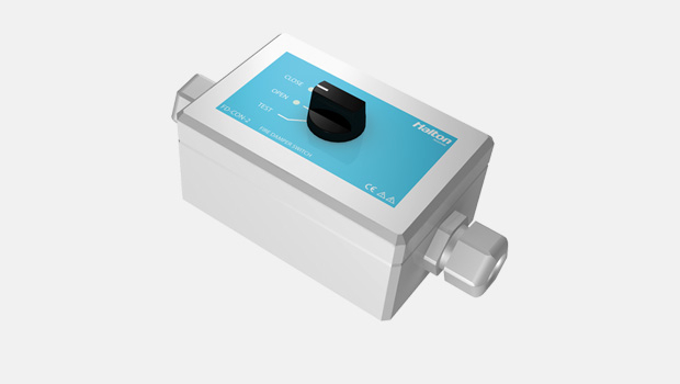
DOT: PNR 和 EL 型号具有手动复位功能
HSO: Halton Smart Override function for HVAC damper black-start available for PNR and EL models. With automatic reset function when power and/or pneumatic air supply is reinstated.用于HVAC风闸黑启动的 Halton 智能手动复位功能适用于 PNR 和 EL 型号。在恢复供电和/或气动供气时,具有自动复位功能。
可提供各种配件。
运行原理
如果管道系统中的温度升高:
- FDB2-EL: 熔断片熔断并切断弹簧复位马达的工作电压,使弹簧关闭风闸叶片。在更换熔断片并重新恢复马达工作电压后,防火风闸会自动打开。
- FDB2-PNR: 熔断器熔断并切断弹簧复位执行器的工作压力,使弹簧关闭风闸叶片。更换熔断片并重新恢复气动供气后,防火风闸会自动打开。
- FDB2-SP: 熔断片熔断,弹簧将关闭风闸叶片。更换熔断片后,必须手动将防火风闸复位到打开位置。
重量
不带执行器的标准浩盾FDB2风闸重量 (kg)
| H/HEIGHT (mm) |
B / WIDTH (mm) | |||||||||||
| 100 | 200 | 300 | 400 | 500 | 600 | 700 | 800 | 900 | 1000 | 1100 | 1200 | |
| 100 | 5 (5) | 7(7) | 9(9) | 10(10) | 12(13) | 14(15) | 15(22) | 17(25) | 19(27) | 20(30) | 22(32) | 24(35) |
| 200 | 7(7) | 9(9) | 11(11) | 12(12) | 14(16) | 16(18) | 18(26) | 20(28) | 22(31) | 23(34) | 25(36) | 27(39) |
| 300 | 9(9) | 11(11) | 13(13) | 15(15) | 17(19) | 19(21) | 21(30) | 23(32) | 25(35) | 27(38) | 29(41) | 31(43) |
| 400 | 11(11) | 13(13) | 15(15) | 17(17) | 20(22) | 22(24) | 24(33) | 26(36) | 28(39) | 30(42) | 32(45) | 34(48) |
| 500 | 13(16) | 16(19) | 18(22) | 21(25) | 23(27) | 25(30) | 28(38) | 30(41) | 32(44) | 35(47) | 37(50) | 39(54) |
| 600 | 15(18) | 18(21) | 20(24) | 23(27) | 25(30) | 28(33) | 30(41) | 33(45) | 35(48) | 38(51) | 40(55) | 43(58) |
| 700 | 18(25) | 21(28) | 23(32) | 26(35) | 29(39) | 32(42) | 34(46) | 37(50) | 40(53) | 42(57) | 45(60) | 48(64) |
| 800 | 20(27) | 23(31) | 25(35) | 28(38) | 31(42) | 34(46) | 37(50) | 40(53) | 43(57) | 46(61) | 49(64) | 51(68) |
| 900 | 22(31) | 25(35) | 28(39) | 32(42) | 35(46) | 38(50) | 41(54) | 44(58) | 47(62) | 50(66) | 53(70) | 56(74) |
| 1000 | 24(33) | 27(37) | 31(41) | 34(45) | 37(50) | 40(54) | 44(58) | 47(62) | 50(66) | 53(70) | 57(74) | 60(78) |
| 1100 | 26(36) | 30(41) | 33(45) | 37(49) | 40(54) | 44(58) | 47(62) | 51(67) | 54(71) | 58(75) | 61(79) | 65(84) |
| 1200 | 28(39) | 32(44) | 36(48) | 39(52) | 43(57) | 46(61) | 50(66) | 54(70) | 57(75) | 61(79) | 65(84) | 68(88) |
| 1300 | 31(42) | 35(47) | 38(52) | 42(56) | 46(61) | 50(66) | 54(70) | 58(75) | 62(80) | 65(84) | 69(89) | 73(94) |
| 1400 | 32(45) | 37(50) | 41(55) | 45(59) | 49(64) | 53(69) | 57(74) | 61(79) | 65(84) | 69(88) | 73(93) | 77(98) |
| 1500 | 35(48) | 39(53) | 43(58) | 48(63) | 52(68) | 53(73) | 60(78) | 65(83) | 69(89) | 73(94) | 77(99) | 82(104) |
| 1600 | 36(51) | 41(56) | 45(61) | 50(66) | 54(72) | 59(77) | 63(82) | 67(87) | 72(92) | 76(98) | 81(103) | 85(108) |
| D2 ØD | WEIGHT |
| (mm) | kg |
| 100 | 8 (8) |
| 125 | 8 (8) |
| 160 | 12 (12) |
| 200 | 13 (13) |
| 250 | 19 (19) |
| 315 | 20 (20) |
| 400 | 27 (27) |
| 500 | 35 (43) |
| 630 | 46 (62) |
| 800 | 62 (89) |
| 1000 | 83 (118) |
| 1250 | 113 (162) |
(框架厚度符合 SOLAS 标准)
执行器重量示例: FDB2-EL GGA 326.1E 2,3 kg, GNA 326.1E 1,3 kg, BF230 +3,2 kg, BLF230 +1,7 kg, ExMax/Redmax +3,5 kg, CSQP +3 kg ,
FDB2-PNR AT100 +2,1 kg, AT100 as AISI316 4,4 kg, AT200 +3,2kg, AT200 as AISI316 +6,2 kg, FDB2-SP +1 kg. Control enclosure +4 kg.
安装
安装在墙壁或屋顶上。
在墙壁上安装时,叶片方向必须始终保持水平。
操作和维护手册可向浩盾船舶销售办事处和经销商索取。
产品代码
| (S)=Shape of Connection | |||||||
| (A) Circular on one side | |||||||
| (C ) Circular on two sides | |||||||
| (R) Rectangular | |||||||
| (W)=Width | |||||||
| 100-1200 | |||||||
| (H)=Height | |||||||
| 100-1600 | |||||||
| (D)=Diameter | |||||||
| 100-1250 | |||||||
| (FA)=Fire Approval | |||||||
| (C1) ABS American Bureau of Shipping | |||||||
| (C2) MED Marine Equipment Directive | |||||||
| (C3) LRS Lloyds Register | |||||||
| (C4) DNV-GL | |||||||
| (C5) BV Bureau Veritas | |||||||
| (C9) RMRS Russian Maritime Register | |||||||
| (EX)=Atex Class | |||||||
| (NA) No | |||||||
| (X1) ATEX certified damper [please fill] | |||||||
| (SF)=Flange Option | |||||||
| (H0) Eurovent flange in circular connections | |||||||
| (H1) Eurovent flange + loose flange in circular connections | |||||||
| (HA) Eurovent flanges | |||||||
| (HB) Eurovent flanges + counter flanges (2 sides) | |||||||
| (HC) Eurovent flanges + counter flange (1 side) | |||||||
| (N0) ISO15138 flange drilling in circular connection | |||||||
| (N1) ISO15138 flange drilling + Loose flange in circular connection | |||||||
| (NA) Circular connections without flanges | |||||||
| (NR) ISO15138 flange drilling | |||||||
| (FS)=Frame Dimensioning | |||||||
| (HS) Manual dimensioning | |||||||
| (SO) SOLAS dimensioning | |||||||
| (S1) SOLAS dimensioning (supplement 2015) | |||||||
| (MA)=Material | |||||||
| (AS) Stainless steel 1 mm EN1.4404 | |||||||
| (CS) Carbon steel 1 mm | |||||||
| (LS) Stainless steel 1 mm EN1.4432 | |||||||
| (SS) Stainless steel 1 mm EN1.4301 | |||||||
| (FM)=Frame Material | |||||||
| (A3) Stainless steel 3 mm EN1.4404 | |||||||
| (A4) Stainless steel 4 mm EN1.4404 | |||||||
| (A5) Stainless steel 5 mm EN1.4404 | |||||||
| (C3) Carbon steel 3 mm | |||||||
| (C4) Carbon steel 4 mm | |||||||
| (C5) Carbon steel 5 mm | |||||||
| (L3) Stainless steel 3 mm EN1.4432 | |||||||
| (L4) Stainless steel 4 mm EN1.4432 | |||||||
| (L5) Stainless steel 5 mm EN1.4432 | |||||||
| (S3) Stainless steel 3 mm EN1.4301 | |||||||
| (S4) Stainless steel 4 mm EN1.4301 | |||||||
| (S5) Stainless steel 5 mm EN1.4301 | |||||||
| (FI)=Finishing | |||||||
| (HG) Hot galvanized | |||||||
| (NA) Acid treatment | |||||||
| (PN) Standard painting grey RAL7001 | |||||||
| (PX) Special Painting C5-M ISO12944 | |||||||
| (IN)=Insulation | |||||||
| (N) No | |||||||
| (Y) A60 insulation on actuator side | |||||||
| (RE)=Actuator | |||||||
| (E1) Electric – Belimo, BF24-2-HL | |||||||
| (E3) Electric – Belimo, BF230-2-HL | |||||||
| (E7) Electric – Belimo, BF120-HL | |||||||
| (E8) Electric – Belimo, NF24A-SR | |||||||
| (E9) Electric – Belimo, NF24A-SR-S2 | |||||||
| (E10) Electric – Belimo, SF24A-SR | |||||||
| (E11) Electric – Belimo, SF24A-SR-S2 | |||||||
| (I1) InMax – Schischek, 15-SF | |||||||
| (I2) InMax – Schischek, 15-SF VAS | |||||||
| (I3) InMax – Schischek, 15-SF1 VAS | |||||||
| (I4) InMax – Schischek, 8-SF-1 | |||||||
| (I6) InMax – Schischek, 15-SF-1 | |||||||
| (I9) InMax – Schischek, 5.10-SF | |||||||
| (I10) InMax – Schischek, 5.10-SF VAS | |||||||
| (I11) InMax – Schischek, 8-SF-1 VAS | |||||||
| (K0) Electric – Belimo, BFN24.1 | |||||||
| (K2) Electric – Belimo, BFN230.1 | |||||||
| (P0) Pneumatic – Air Torque, AT101, Aluminium | |||||||
| (P3) Pneumatic – Air Torque, AT104, AISI316 | |||||||
| (Q1) Pneumatic – Air Torque, AT201, Aluminium | |||||||
| (Q2) Pneumatic – Air Torque, AT204, AISI316 | |||||||
| (S1) Spring | |||||||
| (T1) Electric – Belimo, BF24-T-2.1HL | |||||||
| (T3) Electric – Belimo, BF230-T-2.1HL | |||||||
| (Z2) Electric (EX) – Schischek, ExMax 15-SF | |||||||
| (Z3) Electric (EX) – Schischek, ExMax 5-10SF | |||||||
| (Z4) Electric (EX), Schischek, ExMax 15-SF VAS | |||||||
| (Z5) Electric (EX) – Schischek, ExMax 15-SF1 VAS | |||||||
| (Z6) Electric (EX) – Schischek, ExMax 8-SF1 | |||||||
| (Z7) Electric (EX) – Schischek, ExMax 15-SF1 | |||||||
| (Z10) Electric (EX) – Schischek, ExMax 5.10-SF VAS | |||||||
| (Z11) Electric (EX) – Schischek, ExMax 8-SF1 VAS | |||||||
| (C1) Electric – Elodrive, CSQP-05A1E 24V | |||||||
| (C2) Electric – Elodrive, CSQP-05A2E 120/230V | |||||||
| (C3) Electric – Elodrive, CSQP-10A1E 24V | |||||||
| (C4) Electric – Elodrive, CSQP-10A2E 120/230V | |||||||
| (C5) Electric – Elodrive, CSQP-15A1E 24V – Blocked | |||||||
| (C6) Electric – Elodrive, CSQP-15A2E 120/230V – Blocked | |||||||
| (FU)=Fuse | |||||||
| 144 °C | |||||||
| 100 °C | |||||||
| 95 °C | |||||||
| 74 °C | |||||||
| 72 °C | |||||||
| 70 °C | |||||||
| 65 °C | |||||||
| 50 °C | |||||||
| (AC)=Accessories | |||||||
| (E1) Junction box – Ensto, Plastic, IP66 & 67 | |||||||
| (E2) EX junction box – Cooper, GRP, IP66, T6 | |||||||
| (E4) Cable connectors – Wieland & Hensel | |||||||
| (L2) Limit switch 2 pcs – Bernstein, Plastic, IP66, Mechanical | |||||||
| (L4) EX Limit switch 2 pcs – Bartec, Plastic, IP66, Mechanical | |||||||
| (L5) EX Limit switch 4 pcs – Bartec, Plastic, IP66, Mechanical | |||||||
| (L6) EX Magnetic switch 2 pcs – Elobau, AISI6118, Magnetic | |||||||
| (L7) EX Magnetic switch 4 pcs – Elobau, AISI6118, Magnetic | |||||||
| (L8) EX Magnetic switch 2 pcs – Pepperl & Fuchs, AISI303, Inductive | |||||||
| (L9) EX Magnetic switch 4 pcs – Pepperl & Fuchs, AISI303, Inductive | |||||||
| (M1) Solenoid valve – SMC, Aluminium, 24 VDC | |||||||
| (M2) Solenoid valve – SMC, Aluminium, 230 VAC | |||||||
| (M3) EX solenoid valve – ASCO, Brass, 24 VDC | |||||||
| (M4) EX solenoid valve – ASCO, Brass, 230 VAC | |||||||
| (M5) EX solenoid valve – Bifold, AISI316, 24 VDC | |||||||
| (P1) Manual pneumatic valve – SMC, Aluminium | |||||||
| (P2) Manual pneumatic valve – Bifold, AISI316 | |||||||
| (S3) Limit switch open/Close – Belimo, SN2, Mechanical | |||||||
| (SC) Cover box – Stainless steel | |||||||
| (ST) Pneumatic tubing & fittings – AISI316 | |||||||
| (ED) Manual over-ride handle – Halton DOT or HV-SKU | |||||||
| (O1) Smart override handle – Halton, HSO Schischek | |||||||
| (O2) Smart override handle – Halton, HSO Pneumatic | |||||||
| Code example | |||||||
| FD3/R-1300-1200,FA=C1,SF=HA,FS=SO,MA=CS,FM=C5,FI=HG,RE=Z2,FU=50,ZT=N,AC=E2 | |||||||
Downloads
-
Halton FDB2 datasheet 2025
Data
English -
ABS Certificate for Halton FDB2
Data
English -
BV Certificate for Halton FDB2
Data
English -
CCS Certificate for Halton FDB2
Data
简体中文 (zh) -
DNV Certificate for Halton FDB2
Data
English -
EAC Certificate for Halton FDA, FDB2, FDO, FDH, FCE, UTA, UTG, BDH, BRD, BLD
Data
Русский (ru) -
EC Type Examination Certificate for Halton FDB2
Data
English -
LR Certificate for Halton FDB2
Data
English -
RMRS Certificate for Halton FDB2
Data
Русский (ru) -
TR CU – SAFE Certificate for Halton FDB2, FDL, FEX, UTG, UTX, UTP, UTN, UTT, BLD, BRD
Data
Русский (ru) -
Halton Marine Oy MED Quality System Module D Certificate
Data
English -
SIL 2 Safety Assessment Certificate
Data
English -
ATEX Certificare for FDB2, FDL, FDO, FDA
Data
English -
ClassNK Certificate for Halton FDB2
Data
English
"*" indicates required fields