Product / AIN
概览
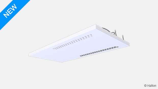
这一生态辐射板压降低,容量大,水流小,材料完全可回收。高效且提供无吹风感的环境。
特点
- 辐射制冷和加热可采用不同的送风分配方法/散流器进行设计,以提供良好的室内气候条件。
- 高冷热输出量
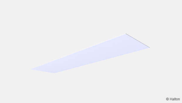
- 低且光滑的设计,表面易于清洁
- 适合集成在天花板中或明装。
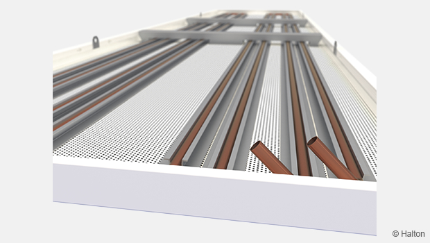
- 带铜管的轻质铝结构
- 符合EN-14037-1:2016的CE认证
产品选型
- 带有一根或两根管道回路(制冷/加热或两者皆有)的辐射板
- 长度从600毫米到3000毫米,宽度从600毫米到1200毫米
- 面板含有或不含绝缘层
- 带穿孔前板和隔热层的辐射板,可实现室内声噪衰减
- 提供定制选型(参见选项卡定制解决方案)
Operating principles
Radiant panels are used as a cooling or heating units. They are draught-free, because the heat transfer is mostly radiation. The heat is transferred from a water flowing through the panel’s copper pipe to the aluminium sheet, which works as a radiant surface to the space. In addition to the radiant heat transfer, the panels use also convection to heat or cool the space. In typical conditions, the ratio between radiant and convective heat transfer is approximately 55:45 in cooling (Fig.1) and 90:10 in heating (Fig.2) with ceiling integrated radiant panels.
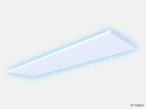
Fig.1. Cooling
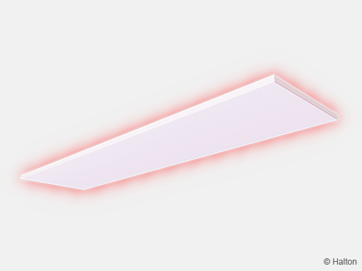
Fig.2. Heating
The panel can achieve its maximum capacity in exposed installation without top insulation, because the upper side is also cooling or heating the space. In ceiling integrated installation, uninsulated panel heats also the space above the suspended ceiling. If necessary, that can be reduced by using insulated panels. Alternatively, panels without top insulation in suspended ceiling can be utilised to conduct cooling or heating capacity through the slab to the upper floor.
Effective area and capacity measurements
Effective panel area is the area of a radiant panel covered with heat exchanger piping. In Halton Ava AIN radiant panel, the effective area is calculated as W-8 * L-100 [mm]. The cooling capacity of radiant panels is measured according to the standard EN-14240. The standard describes the specification of cooling capacity measurement of the radiant panel in exposed and ceiling integrated installations.
The capacity of radiant panels is dependent on the ratio of the effective panel area to the whole ceiling area. Decreasing the ratio increases the capacity of the effective panel area. Cooling capacity measurement according to the standard EN-14240 requires the ratio being less than 50% in exposed installation. In ceiling integrated installation, the ratio shall be over 70%. The effect of the ratio is considered in Halton HIT Design or Halton eHIT selecting tool. The panel capacities can be calculated also without the ratio effect if needed. Also, both cases of the EN-14240 can be calculated with the tool.
The standardised measurement of the heating capacity is done according to EN-14037:2016, which includes five parts. CE-mark and Declaration of Performance is required for radiant panels used for heating. This includes measurement results for the CE mark according to the EN-14037-2. This measurement has been done in accredited laboratory WSPLab (notified body) for Halton Ava Individual top-insulated radiant panels in exposed installation. The measurement standard EN-14037-5 (part 5) contains also other standardised measurements of the radiant panel heating capacity.
Perforated models
Perforated radiant panels (PE=A), are often used for acoustic (with insulation IN=P) or architectural reasons, but they can also offer additional capacity. Uninsulated and perforated panel in exposed installation has more capacity compared to an unperforated panel, because the air is moving trough the panel. The increased capacity is approximately 10% and can be calculated with Halton HIT Design’s performance tool.
Increasing capacity by ventilation
Convective heat transfer and the total capacity of the radiant panel can be increased with air distribution. The total capacity will increase in the areas where supply air jets are flushing the radiant panel surface. Typically, the increase can be 5–10% in cooling conditions (with 16 °C supply air temperature) and 10–30% in heating conditions, depending on the air distribution method and operating conditions. This effect is not included in Halton HIT Design and should be analysed separately.
Features and options
| Accessory/option | Code | Description | Note |
| Number of loops | NL=1 | 1 loop (cooling or heating) | – |
| NL=2 | 2 loops (cooling and heating) | – | |
| Insulation | IN=P | Polyester fibre (Fig.1.) | – |
| Perforation | PE=A | 23% open area (Fig.2.) | Only available for 600 mm wide models |
| Adjustable hanging wires | AC=W4 or W6 | Adjustable hanging wires, L=1,3 m (Fig. 3.) | 4 or 6 pieces depending on the no. fixing points |
| Flexible hoses | AC=FH2 or FH4 | Flexible hose, L=0,5 m. 10 mm quick connectors (straight + 90° angle) |
2 or 4 pieces depending on the no. of loops |
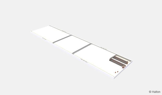
Fig.1. Insulated model (IN=P)
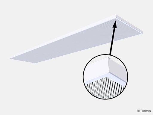
Fig.2. Perforated model (PE=A)
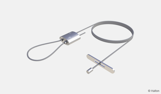
Fig.3. Adjustable hanging wire (AC= W4 or W6)
Structure and materials
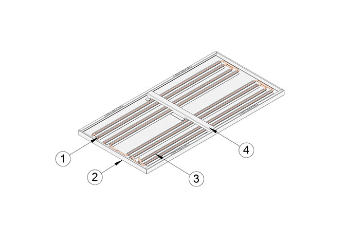
| No. | Part | Description | Note |
| 1 | Heat exchanger pipes | Copper | Ø 10 mm |
| 2 | Front panel | Pre-painted aluminium |
Polyester-painted, white (RAL 9003/20%) |
| 3 | Pipe fixing profiles | Aluminium | – |
| 4 | Cross supports | Aluminium | – |
Dimensions and weight
Halton Ava AIN radiant panels are available in three widths and six lengths. The widths are 600, 900 and 1200 mm and lengths 600, 1200, 1800, 2400, 3000 and 3600 mm. The panels are 35 mm high.
Also project specific special sizes to maximum length of 3600 mm and width of 1200 mm are available. Integration of air distribution, lighting and other building services is also available.
Please contact Halton sales for further information.
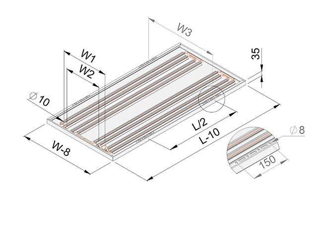
Fig.1. Dimensions with 4 installation brackets (see table below)
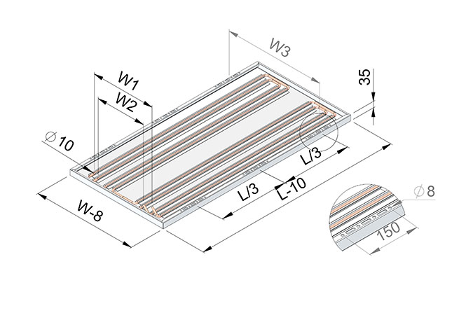
Fig.2. Dimensions with 6 installation brackets (see table below)
| W | 600 | 900 | 1200 | ||
| W1 Pipe spacing, loop 1 [mm] |
366 | 662 | 958 | ||
| W2 * Pipe spacing, loop 2 [mm] |
286 | 582 | 286 | ||
| W3 Bracket spacing [mm] |
552 | 852 | 1152 | ||
| Dry mass, NL=1 / NL=2 (kg/m) |
3.7 / 5.3 | 5.5 / 7.0 | 7.2 / 8.8 | ||
| Water volume, NL=1 / NL=2 (kg/m) |
0.3 / 0.5 | 0.4 / 0.7 | 0.5 / 0.8 | ||
| Number of brackets |
L |
600 | 4 | NA | NA |
| 1200 | 4 | 4 | 4 | ||
| 1800 | 4 | 4 | 4 | ||
| 2400 | 4 | 6 | 6 | ||
| 3000 | 4 | 6 | 6 | ||
| 3600 | 6 | 6 | 6 | ||
Specification
The radiant panel is 592, 892 or 1192 mm wide and 35 mm thick.
The radiant panel and cross supports are made of aluminium.
The installation brackets are made of galvanised steel.
All visible parts are white, 20% gloss.
All pipes are manufactured from copper.
Maximum operation pressure for the pipework is 1.0 MPa.
Visible surfaces of the radiant panels are protected by removable plastic coating.
The pipe ends are sealed during delivery.
The radiant panels are identified by a label attached to the top side of the panel.
Order code
AIN-L-W; NL-IN-PE-CO-ZT
L = Length of radiant panel [mm]
600, 1200, 1800, 2400, 3000, 3600
W = Width of radiant panel [mm]
600, 900, 1200
Other options and accessories
NL = Number of loops
1 1 loop (cooling or heating)
2 2 loops (cooling and heating)
IN = Insulation
NA Not assigned
P Polyester fibre
PE = Perforation
NA Not assigned
A Perforation 23%
CO = Colour
SW Signal white (RAL 9003)
X Special colour (RAL xxxx)
AC = Accessories
W4 Adjustable hanging wire, 1,3m (4 pcs)
W6 Adjustable hanging wire, 1,3m (6 pcs)
FH2 Flex. hose, 0,5m, 10mm 0°+90° (2 pcs)
FH4 Flex. hose, 0,5m, 10mm 0°+90° (4 pcs)
ZT = Tailored product
N No
Y Yes (ETO)
Order code example
AIN-1200-600, NL=1, IN=P, PE=NA, ZT=N
Installation
Halton Ava AIN radiant panels are suitable for exposed and ceiling integrated installation.
Installation is easy with multiple fixing point options (Fig 1.) and adjustable wires (W4 or W6, available as accessories). 500 mm flexible hoses with straight and elbow quick connectors are also available as accessories (FH2 or FH4).
See detailed installation guide from Downloads.
Fig.1. Installed panel with adjustable wires
Commissioning
Cooling
The recommended cooling water mass flow rate is 0.020-0.035 kg/s, resulting in a temperature rise of 1-3 °C in the heat exchanger. To avoid condensation, the recommended inlet water temperature of the heat exchanger is over 14 °C.
Heating
The recommended heating water mass flow rate is 0.015-0.030 kg/s, resulting in a temperature drop of 3-10 °C in the heat exchanger. In typical rooms (room height up to 3 m), usual recommended maximum temperature of the inlet water is 50 °C due to the risk of too high radiation asymmetry. With exposed installation to minimum 3 m from floor and with effective panel area / whole ceiling area less than 50% also higher inlet water temperature (e.g. 60 °C) can be used without risk of too high radiant asymmetry.
Maintenance
No regular maintenance is required for the product.
Clean the front panel and other visible painted plates using a damp cloth.
Also, the top side of the radiant panel in exposed installation can be easily cleaned with a vacuum cleaner or a damp cloth.
Customised solutions
Halton Ava family products are suitable for customised solutions. Examples of those solutions are presented below. Please contact sales for further information.
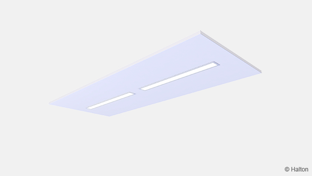
Lighting and other accessories
Halton Ava radiant panels can be equipped with lighting, different kind of sensors, sprinklers etc. according to the project specific requirements.
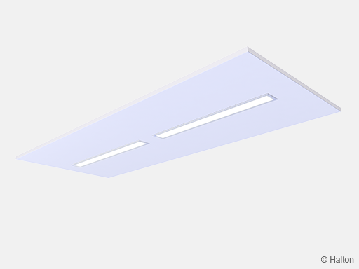
Fig.1. Solution of radiant panel with lights
Digital Coating
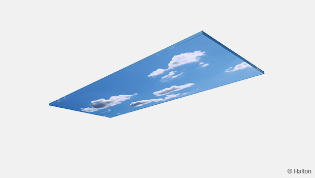
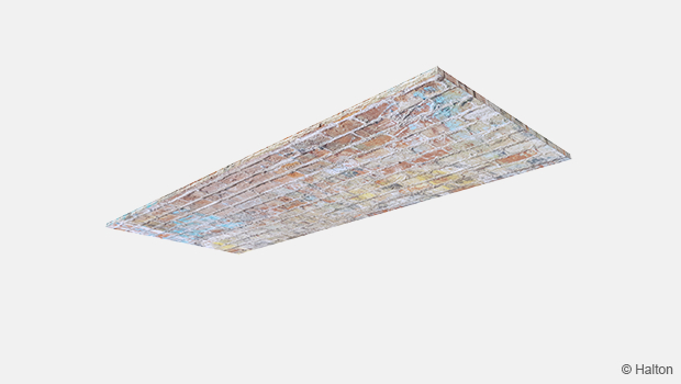
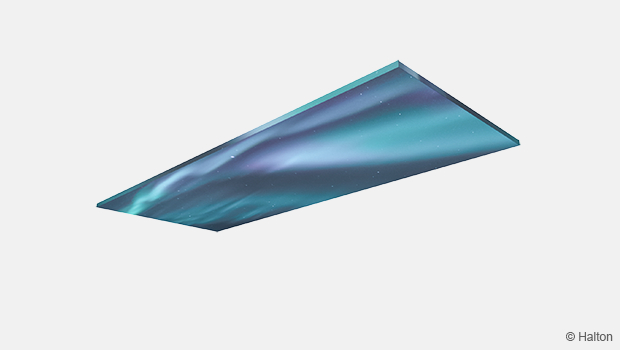
Images are possible to transfer to the visible surface of Halton Ava radiant panels. The coating has high wearing resistance for UV radiation and abrasion. Imitation of different materials is also possible.
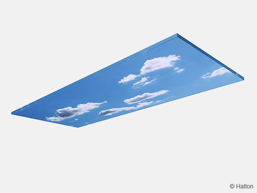
Fig.2. Solution of a radiant panel with an image of the summer sky *)
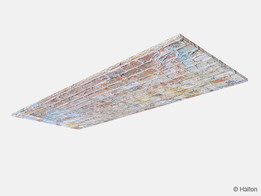
Fig.3. Solution for radiant panel with brick wall appearance *)
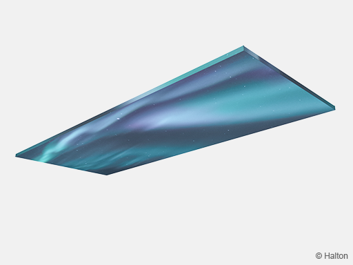
Fig.4. Solution for radiant panel with northern lights *)
*) Image is only an illustration of the presented solution.
Downloads
-
Halton Ava AIN – Radiant panel
Data
en
-
Halton Ava AIN – Säteilypaneeli
Data
fi
-
Halton Ava AIN 辐射板
Data
cn
-
Installation guide – Halton Ava AIN
Data
English (en) -
Asennusohje – Halton Ava AIN
Data
Suomi (fi) -
Suoritustasoilmoitus (DoP) – Halton Ava AIN
Data
Suomi (fi) -
Declaration of Performance (DoP) – Halton Ava AIN
Data
English (en)
"*" indicates required fields