Product / BDH
BDH 抗爆风闸
Halton BDH 抗爆风闸可在海上、陆上和重工业保护通风系统免受超压影响。
概览
- 爆轰(冲击)型压力波冲击管试验
- 爆燃(爆炸)型压力波冲击管试验
- 冲击管测试符合GSA TS01和ASTM F 1642-04(2010)
- 碎片(钢球和木板条投掷物)冲击测试
- 碎片冲击试验符合ASTM E 1886-13a和ASTM E 1996-14a
- 根据EN 1751进行空气动力学测试
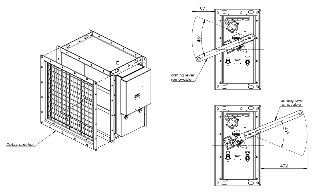
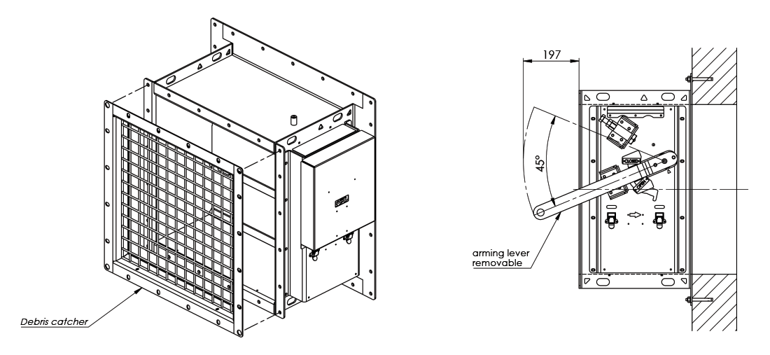
- 叶片角度的正常开启位置为45度
- 通过ATEX/IECEx认证
- 建议最大风速为10 m/s
- 最大冲击波压力为1.0 bar
- 不锈钢抗爆阀的正常工作温度为 -60 ºC ~ +80 ºC
- 碳钢抗爆阀的正常工作温度为 -20 ºC ~ +80 ºC
规格
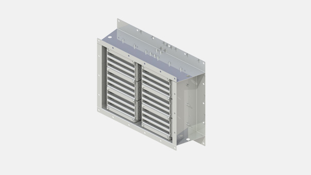
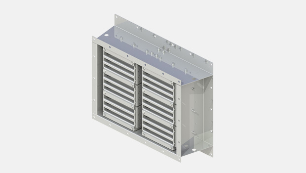
Halton BDH 抗爆风闸可以在海上、路上、重工业通风系统中防止超压产生。BDH 抗爆风闸可安装在矩形管道或墙壁开口中。当叶片处于开启位置时,该装置不会造成明显的压力损失、噪音或扰流。BDH有一个可调节的报警机制,以应对不同的风速和关闭压力要求。在抗爆阀外侧可以看到一个打开-关闭指示器。
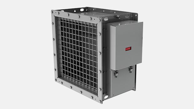
不需要外部电源来运行抗爆风闸。如果发生爆炸事件,压力波会关闭叶片。 有一个锁定机构,防止叶片在负相位打开。发生爆炸事件后,叶片保持锁定在关闭位置,直到重置(启用)抗爆阀。
尺寸和材料厚度
BDH 抗爆风闸适用于矩形管道和墙洞。宽度B为300-1200mm,以25mm为单位划分。高度H为200-1200mm,以50mm为单位划分。对于更大尺寸,可采用模块化结构。
标准配置中,法兰宽度和螺栓孔的钻孔均遵循ISO 15138国际标准。
框架深度为400mm,框架厚度为5mm。
叶片厚度为5mm,叶片轴直径为25mm。叶片通过螺栓固定在轴上。
抗爆阀有1-6个叶片。在多叶片抗爆阀(2-6个叶片)中,叶片通过连杆连接并平行运行。连杆厚度为8mm。
碎屑收集器由直径为6mm的钢丝制成。钢丝之间的开放区域为40 x 40mm。
通用BDH图纸
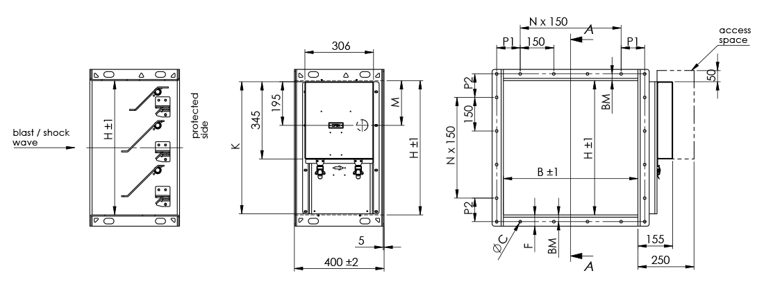
| H | M | K |
|---|---|---|
| 1200 | 200 | 1190 |
| 1150 | 200 | 1140 |
| 1100 | 200 | 1090 |
| 1050 | 200 | 1040 |
| 1000 | 200 | 990 |
| 950 | 200 | 940 |
| 900 | 200 | 890 |
| 850 | 200 | 840 |
| 800 | 200 | 790 |
| 750 | 200 | 740 |
| 700 | 200 | 690 |
| 650 | 200 | 640 |
| 600 | 200 | 590 |
| 550 | 200 | 540 |
| 500 | 200 | 490 |
| 450 | 250 | 440 |
| 400 | 200 | 435 |
| 350 | 200 | 435 |
| 300 | 50 | 440 |
| 250 | 50 | 435 |
| 200 | 50 | 435 |
| 抗爆阀尺寸 BxH | 钢墙/管道围缘的开孔尺寸 (最大) BxH |
|---|---|
| 300×300 | 300×300 |
| 400×400 | 400×400 |
| 500×500 | 500×500 |
| 600×600 | 600×600 |
| 700×700 | 700×700 |
| 800×800 | 800×800 |
| 900×900 | 900×900 |
| 1000×1000 | 1000×1000 |
| 1100×1100 | 1100×1100 |
| 1200×1200 | 1200×1200 |
根据ISO 15138标准的法兰尺寸
| 尺寸 | ØC | 螺栓 | P1, P2 | BM | F |
|---|---|---|---|---|---|
| 如果最长边 < 350 | 10 | M8 | 75…150 | 20 | 40 |
| 如果最长边 351…1000 | 12 | M10 | 75…150 | 30 | 50 |
| 如果最长边 > 1001 | 14 | M12 | 75…150 | 40 | 80 |
适用于混凝土墙的通用BDH图纸
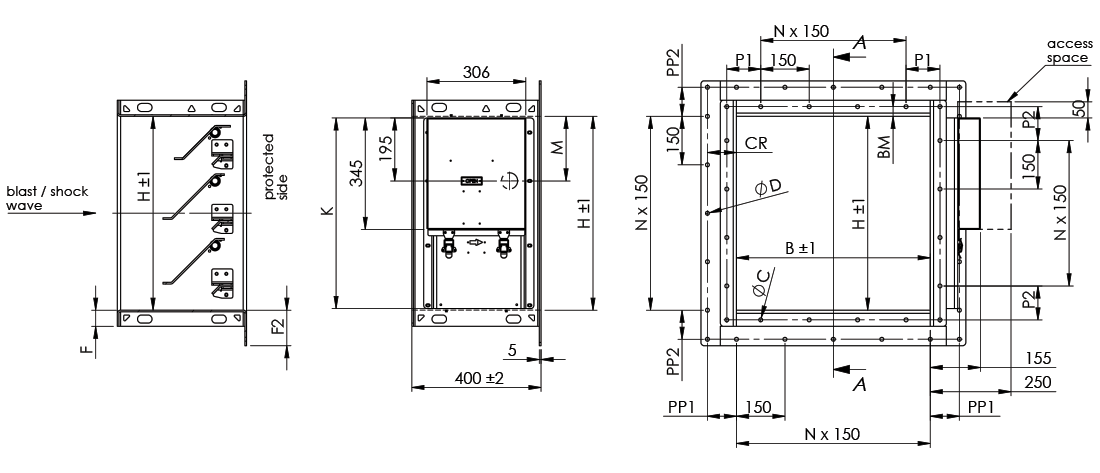
| H | M | K |
|---|---|---|
| 1200 | 200 | 1190 |
| 1150 | 200 | 1140 |
| 1100 | 200 | 1090 |
| 1050 | 200 | 1040 |
| 1000 | 200 | 990 |
| 950 | 200 | 940 |
| 900 | 200 | 890 |
| 850 | 200 | 840 |
| 800 | 200 | 790 |
| 750 | 200 | 740 |
| 700 | 200 | 690 |
| 650 | 200 | 640 |
| 600 | 200 | 590 |
| 550 | 200 | 540 |
| 500 | 200 | 490 |
| 450 | 250 | 440 |
| 400 | 200 | 435 |
| 350 | 200 | 435 |
| 300 | 50 | 440 |
| 250 | 50 | 435 |
| 200 | 50 | 435 |
| 抗爆阀尺寸 BxH | 混凝土墙上的开孔尺寸BxH |
|---|---|
| 300×300 | 300×300 |
| 400×400 | 400×400 |
| 500×500 | 500×500 |
| 600×600 | 600×600 |
| 700×700 | 700×700 |
| 800×800 | 800×800 |
| 900×900 | 900×900 |
| 1000×1000 | 1000×1000 |
| 1100×1100 | 1100×1100 |
| 1200×1200 | 1200×1200 |
根据ISO 15138标准的法兰尺寸
| 尺寸 | ØC | 螺栓 | P1, P2 | BM | F | P1, P2 | CR | F2 |
|---|---|---|---|---|---|---|---|---|
| 如果最长边< 350 | 10 | M8 | 75…150 | 20 | 40 | 75…150 | 75 | 95 |
| 如果最长边 351…1000 | 12 | M10 | 75…150 | 30 | 50 | 75…150 | 90 | 110 |
| 如果最长边 > 1001 | 14 | M12 | 75…150 | 40 | 80 | 75…150 | 105 | 145 |
材料和表面处理
| 零件 | 材料 | 表面处理 |
|---|---|---|
| 框架 | 碳钢 | 涂漆或热浸镀锌 |
| 框架 | 不锈钢 EN 1.4404 (AISI 316L) |
– |
| 叶片 | 碳钢 | 热浸镀锌 |
| 叶片 | 不锈钢 EN 1.4404 (AISI 316L) |
– |
| 调节、关闭和锁定机构 | 不锈钢 EN 1.4404 (AISI 316L) 一部分零件EN 1.4305 (AISI 303)或类似 |
– |
| 免维护轴承 | 不锈钢 EN 1.4404 (AISI 316L) |
– |
| 轴 | 不锈钢 EN 1.4404 (AISI 316L) |
– |
| 碎屑收集器 | 碳钢 | 热浸镀锌 |
| 碎屑收集器 | 不锈钢 EN 1.4404 (AISI 316L) |
– |
产品型号和附件
用于打开抗爆风闸的启动工具,每栋建筑至少配备一个工具。阻挡大型物体进入保护区的碎屑收集器。用于人员安全的网状手指防护罩,防止触摸到已启动的叶片。可以安装在受保护侧、暴露侧或两侧。
高度
Halton Marine 标准BDH抗爆风闸 (kg)
| H / 高度 (mm) |
B / 宽度 (mm) | |||||||||
|---|---|---|---|---|---|---|---|---|---|---|
| 300 | 400 | 500 | 600 | 700 | 800 | 900 | 1000 | 1100 | 1200 | |
| 200 | 41 | 43 | 46 | 49 | 52 | 55 | 57 | 60 | 63 | 66 |
| 300 | 52 | 56 | 60 | 63 | 67 | 71 | 75 | 79 | 83 | 87 |
| 400 | 63 | 68 | 73 | 78 | 83 | 88 | 93 | 98 | 103 | 108 |
| 500 | 74 | 80 | 86 | 92 | 99 | 105 | 111 | 117 | 123 | 129 |
| 600 | 85 | 92 | 100 | 107 | 114 | 122 | 129 | 136 | 143 | 151 |
| 700 | 96 | 105 | 113 | 122 | 130 | 138 | 147 | 155 | 164 | 172 |
| 800 | 107 | 117 | 126 | 136 | 146 | 155 | 165 | 174 | 184 | 193 |
| 900 | 122 | 133 | 143 | 154 | 165 | 175 | 186 | 197 | 207 | 218 |
| 1000 | 133 | 145 | 157 | 168 | 180 | 192 | 204 | 216 | 227 | 239 |
| 1100 | 144 | 157 | 170 | 183 | 196 | 209 | 222 | 235 | 248 | 260 |
| 1200 | 155 | 169 | 183 | 197 | 211 | 226 | 240 | 254 | 268 | 282 |
适用于混凝土墙的Halton Marine 标准BDH抗爆阀(kg)
| H / 高度 (mm) |
B / 宽度 (mm) | |||||||||
|---|---|---|---|---|---|---|---|---|---|---|
| 300 | 400 | 500 | 600 | 700 | 800 | 900 | 1000 | 1100 | 1200 | |
| 200 | 44 | 47 | 50 | 53 | 56 | 59 | 62 | 65 | 68 | 71 |
| 300 | 55 | 60 | 64 | 68 | 72 | 76 | 80 | 84 | 89 | 93 |
| 400 | 67 | 72 | 78 | 83 | 88 | 94 | 99 | 104 | 110 | 115 |
| 500 | 79 | 85 | 92 | 98 | 105 | 111 | 118 | 124 | 131 | 137 |
| 600 | 90 | 98 | 106 | 113 | 121 | 129 | 136 | 144 | 152 | 159 |
| 700 | 102 | 111 | 120 | 129 | 137 | 146 | 155 | 164 | 173 | 181 |
| 800 | 114 | 124 | 134 | 144 | 154 | 164 | 174 | 184 | 193 | 203 |
| 900 | 129 | 140 | 151 | 162 | 173 | 185 | 196 | 207 | 218 | 229 |
| 1000 | 141 | 153 | 165 | 177 | 190 | 202 | 214 | 227 | 239 | 251 |
| 1100 | 152 | 166 | 179 | 193 | 206 | 219 | 233 | 246 | 260 | 273 |
| 1200 | 164 | 179 | 193 | 208 | 222 | 237 | 252 | 266 | 281 | 295 |
安装
可以垂直安装在建筑物外墙外或风管法兰之间。此外,还可以水平安装在风管、地板或屋顶上,但仅适用于从上至下的爆炸方向。
墙体(或地板/屋顶)材料可以是混凝土或钢材
对于混凝土墙体的安装,使用宽法兰版本,并通过锚固螺栓进行安装。
对于钢结构墙体的安装,抗爆风闸通过螺栓固定或焊接的方式进行安装。
更详细的安装指南可以在BDH安装、操作和维护手册中找到。
Downloads
"*" indicates required fields