Product / BDH
BDH – Blast protection damper
Halton BDH blast dampers protect against overpressure in offshore, onshore and heavy industry ventilation systems.

Overview
- Shock tube tested for detonation (shock) type pressure wave
- Shock tube tested for deflagration (blast) type pressure wave
- Shock tube testing in compliance with GSA TS01 and ASTM F 1642-04(2010)
- Debris (steel balls and wood plank missile) impact tested
- Debris impact testing in compliance with ASTM E 1886-13a and ASTM E 1996-14a
- Aerodynamic testing according to EN 1751
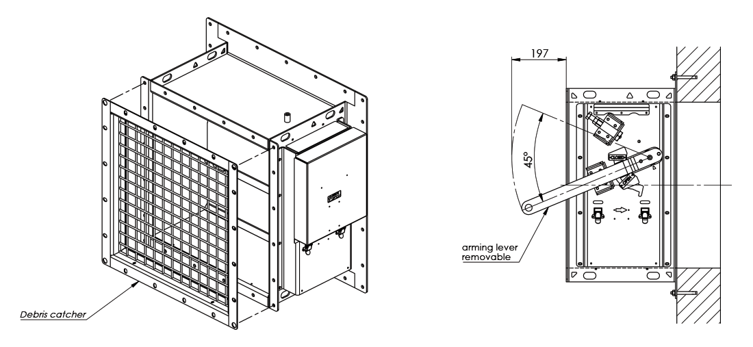
- The normal open position of the blade angle is 45 degrees
- ATEX/IECEx certified
- Recommended maximum air velocity is 10 m/s
- Maximum shock and blast wave pressure is 1.0 bar
- The normal operating temperature for a stainless steel damper is between -60 ºC to +80 ºC
- The normal operating temperature for a carbon steel damper is between -20 ºC to +80 ºC
Specification
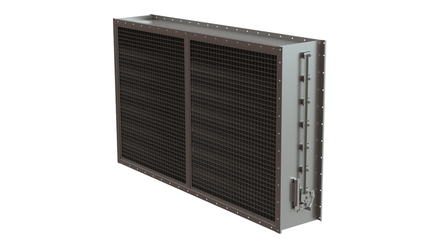
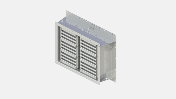
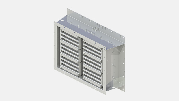
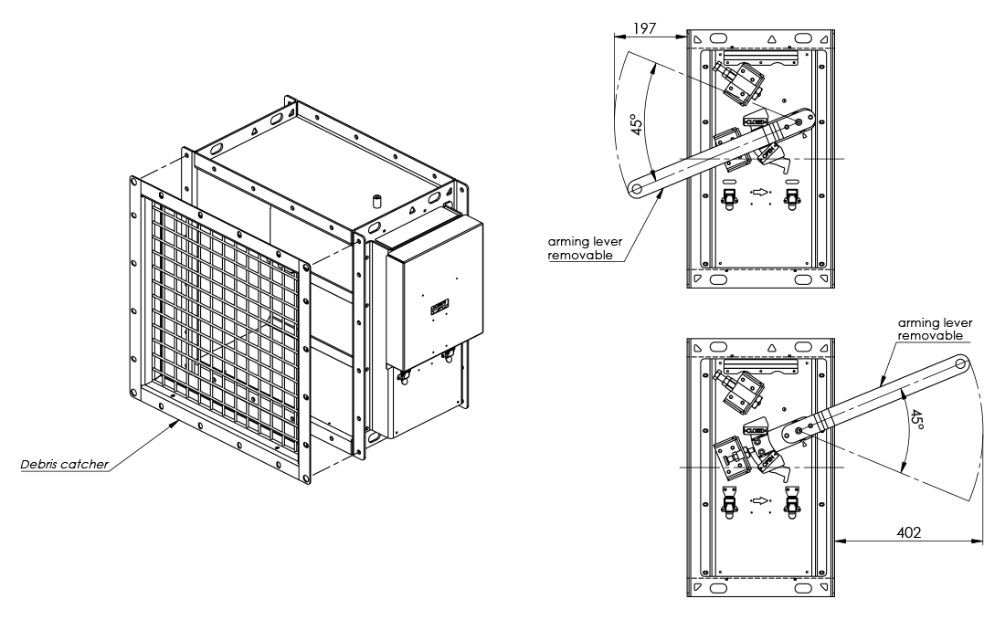
Halton BDH blast dampers protect against overpressure in offshore, onshore and heavy industry ventilation systems. The BDH blast damper can be installed in rectangular ducts or wall openings. When the blades are in the open position, the device does not cause significant pressure loss, noise or flow disturbance. The BDH has an adjustable arming mechanism to cope with different air velocity and closing pressure requirements. An open-closed indicator is visible on the outside of the damper.
There is no external power source needed to operate the damper. In case of a blast incident, the pressure wave closes the blades. There is a locking mechanism preventing the blades from opening during the negative phase. After a blast incident, the blades remain locked in the closed position, until the damper is set (armed) again.
Dimensions and Material Thickness
BDH blast protection dampers are available for rectangular ducts and wall openings. Width B is 300-1200 mm, 25 mm division. Height H is 200-1200 mm, 50 mm division. Modular construction is available for larger sizes.
As a standard, flange width and bolt hole drilling are according to ISO 15138 standard.
Frame depth is 400 mm, frame thickness is 5 mm.
Blade thickness is 5 mm, blade shaft diameter is 25 mm. Blades are bolted to shafts.
The damper has 1-6 blades. In a multiblade damper (2-6 blades), blades are connected via linkage and operate in parallel. Linkage thickness is 8 mm.
The debris catcher is a diameter of 6 mm wire. The open area between wires is 40 x 40 mm.
General BDH drawings
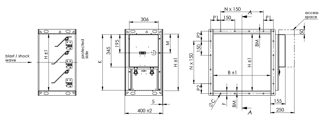
| H | M | K |
|---|---|---|
| 1200 | 200 | 1190 |
| 1150 | 200 | 1140 |
| 1100 | 200 | 1090 |
| 1050 | 200 | 1040 |
| 1000 | 200 | 990 |
| 950 | 200 | 940 |
| 900 | 200 | 890 |
| 850 | 200 | 840 |
| 800 | 200 | 790 |
| 750 | 200 | 740 |
| 700 | 200 | 690 |
| 650 | 200 | 640 |
| 600 | 200 | 590 |
| 550 | 200 | 540 |
| 500 | 200 | 490 |
| 450 | 250 | 440 |
| 400 | 200 | 435 |
| 350 | 200 | 435 |
| 300 | 50 | 440 |
| 250 | 50 | 435 |
| 200 | 50 | 435 |
| Damper size BxH | Opening size steel wall / duct coaming (max) BxH |
|---|---|
| 300×300 | 300×300 |
| 400×400 | 400×400 |
| 500×500 | 500×500 |
| 600×600 | 600×600 |
| 700×700 | 700×700 |
| 800×800 | 800×800 |
| 900×900 | 900×900 |
| 1000×1000 | 1000×1000 |
| 1100×1100 | 1100×1100 |
| 1200×1200 | 1200×1200 |
Flange dimensions according to ISO 15138
| DIMENSIONS | ØC | Bolt | P1, P2 | BM | F |
|---|---|---|---|---|---|
| If longest side < 350 | 10 | M8 | 75…150 | 20 | 40 |
| If longest side 351…1000 | 12 | M10 | 75…150 | 30 | 50 |
| If longest side > 1001 | 14 | M12 | 75…150 | 40 | 80 |
General BDH drawings for concrete wall
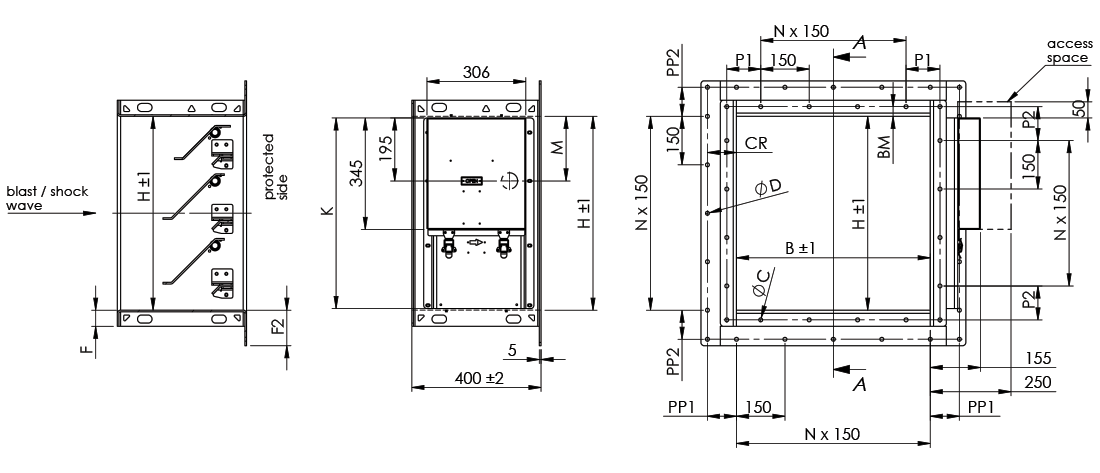
| H | M | K |
|---|---|---|
| 1200 | 200 | 1190 |
| 1150 | 200 | 1140 |
| 1100 | 200 | 1090 |
| 1050 | 200 | 1040 |
| 1000 | 200 | 990 |
| 950 | 200 | 940 |
| 900 | 200 | 890 |
| 850 | 200 | 840 |
| 800 | 200 | 790 |
| 750 | 200 | 740 |
| 700 | 200 | 690 |
| 650 | 200 | 640 |
| 600 | 200 | 590 |
| 550 | 200 | 540 |
| 500 | 200 | 490 |
| 450 | 250 | 440 |
| 400 | 200 | 435 |
| 350 | 200 | 435 |
| 300 | 50 | 440 |
| 250 | 50 | 435 |
| 200 | 50 | 435 |
| Damper size BxH | Opening size concrete wall BxH |
|---|---|
| 300×300 | 300×300 |
| 400×400 | 400×400 |
| 500×500 | 500×500 |
| 600×600 | 600×600 |
| 700×700 | 700×700 |
| 800×800 | 800×800 |
| 900×900 | 900×900 |
| 1000×1000 | 1000×1000 |
| 1100×1100 | 1100×1100 |
| 1200×1200 | 1200×1200 |
Flange dimensions according to ISO 15138
| DIMENSIONS | ØC | Bolt | P1, P2 | BM | F | P1, P2 | CR | F2 |
|---|---|---|---|---|---|---|---|---|
| If longest side < 350 | 10 | M8 | 75…150 | 20 | 40 | 75…150 | 75 | 95 |
| If longest side 351…1000 | 12 | M10 | 75…150 | 30 | 50 | 75…150 | 90 | 110 |
| If longest side > 1001 | 14 | M12 | 75…150 | 40 | 80 | 75…150 | 105 | 145 |
Material and Finishing
| PART | MATERIAL | FINISHING |
|---|---|---|
| Frame | Carbon steel | Painted or hot-dip galvanised |
| Frame | Stainless steel EN 1.4404 (AISI 316L) |
– |
| Blades | Carbon steel | Hot-dip galvanised |
| Blades | Stainless steel EN 1.4404 (AISI 316L) |
– |
| Setting, closing and locking mechanism | Stainless steel EN 1.4404 (AISI 316L) and some parts EN 1.4305 (AISI 303) or similar |
– |
| Maintenance-free bearings | Stainless steel EN 1.4404 (AISI 316L) |
– |
| Shafts | Stainless steel EN 1.4404 (AISI 316L) |
– |
| Debris catcher | Carbon steel | Hot-dip galvanised |
| Debris catcher | Stainless steel EN 1.4404 (AISI 316L) |
– |
Product Models and Accessories
Arming tool to open the damper, at least one tool per building.
Debris catcher to prevent large objects from entering the protected area.
Mesh finger guard for personnel safety to prevent touching armed blades. Can be installed on the protected side, exposed side or both.
Weights
Standard Halton Marine BDH dampers (kg)
| H / HEIGHT (mm) |
B / WIDTH (mm) | |||||||||
|---|---|---|---|---|---|---|---|---|---|---|
| 300 | 400 | 500 | 600 | 700 | 800 | 900 | 1000 | 1100 | 1200 | |
| 200 | 41 | 43 | 46 | 49 | 52 | 55 | 57 | 60 | 63 | 66 |
| 300 | 52 | 56 | 60 | 63 | 67 | 71 | 75 | 79 | 83 | 87 |
| 400 | 63 | 68 | 73 | 78 | 83 | 88 | 93 | 98 | 103 | 108 |
| 500 | 74 | 80 | 86 | 92 | 99 | 105 | 111 | 117 | 123 | 129 |
| 600 | 85 | 92 | 100 | 107 | 114 | 122 | 129 | 136 | 143 | 151 |
| 700 | 96 | 105 | 113 | 122 | 130 | 138 | 147 | 155 | 164 | 172 |
| 800 | 107 | 117 | 126 | 136 | 146 | 155 | 165 | 174 | 184 | 193 |
| 900 | 122 | 133 | 143 | 154 | 165 | 175 | 186 | 197 | 207 | 218 |
| 1000 | 133 | 145 | 157 | 168 | 180 | 192 | 204 | 216 | 227 | 239 |
| 1100 | 144 | 157 | 170 | 183 | 196 | 209 | 222 | 235 | 248 | 260 |
| 1200 | 155 | 169 | 183 | 197 | 211 | 226 | 240 | 254 | 268 | 282 |
Standard Halton Marine BDH dampers for concrete wall (kg)
| H / HEIGHT (mm) |
B / WIDTH (mm) | |||||||||
|---|---|---|---|---|---|---|---|---|---|---|
| 300 | 400 | 500 | 600 | 700 | 800 | 900 | 1000 | 1100 | 1200 | |
| 200 | 44 | 47 | 50 | 53 | 56 | 59 | 62 | 65 | 68 | 71 |
| 300 | 55 | 60 | 64 | 68 | 72 | 76 | 80 | 84 | 89 | 93 |
| 400 | 67 | 72 | 78 | 83 | 88 | 94 | 99 | 104 | 110 | 115 |
| 500 | 79 | 85 | 92 | 98 | 105 | 111 | 118 | 124 | 131 | 137 |
| 600 | 90 | 98 | 106 | 113 | 121 | 129 | 136 | 144 | 152 | 159 |
| 700 | 102 | 111 | 120 | 129 | 137 | 146 | 155 | 164 | 173 | 181 |
| 800 | 114 | 124 | 134 | 144 | 154 | 164 | 174 | 184 | 193 | 203 |
| 900 | 129 | 140 | 151 | 162 | 173 | 185 | 196 | 207 | 218 | 229 |
| 1000 | 141 | 153 | 165 | 177 | 190 | 202 | 214 | 227 | 239 | 251 |
| 1100 | 152 | 166 | 179 | 193 | 206 | 219 | 233 | 246 | 260 | 273 |
| 1200 | 164 | 179 | 193 | 208 | 222 | 237 | 252 | 266 | 281 | 295 |
Installation
The damper can be installed vertically outside of the building wall or between duct flanges. Also, horizontal installation is possible on the duct, floor or roof but only in the top-down blast direction.
The wall (or floor/roof) material can be concrete or steel.
For concrete wall installation, a wide-flange version is used and the damper is installed using anchor bolts.
For steel wall installation, the damper is installed using bolts or by welding.
Detailed installation information is available in the BDH installation, operation and maintenance manual.
Downloads
Request for Quotation
"*" indicates required fields