Product / RE6
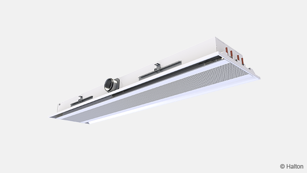
浩盾 Rex 600 (RE6)
适合高质量通风的浩盾 Rex冷梁家族新成员!
- 采用嵌入式吊顶安装的集制冷、供热和送风一体的设备。
- 特别适合高制冷负荷、低湿负荷和多变通风需求的空间。
概览
- 采用嵌入式吊顶安装的集制冷、供热和送风一体的设备。
- 特别适合高制冷负荷、低湿负荷和多变通风需求的空间。
- 更是高质量环境条件、按需通风和独立房间控制应用的理想解决方案。
典型应用:办公室房间、大开间办公室和会议室。
浩盾 Rex 600冷梁是为典型办公室空间的风量调节高灵活性的通风需求所设计的。浩盾 Rex 600的运行可以很容易的适应于改变的运行条件和从设计到建筑生命周期结束的需求。
- 容易且快速的选择
- Halton速度控制 (HVC) 可实现独立速度调节
- 借助Halton速度控制HVC可轻松实现隔墙的重新灵活定位
- 使用Halton空气质量控制器(HAQ)可独立调节空间布局变化时的送风量
- 为恒定的有效使用能源而按需控制送风量—压力管道系统区域的应用;当风量的改变对冷梁的盘管制冷/供热负荷没有影响时。
- 现场物流高效
- 通过优化水量和风量来提升生命周期性能
产品型号&附件
- 配有组合式制冷和供热交换器的型号
- 配有手动或者电动的Halton空气质量控制器(HAQ)的型号
- 配有集成排风阀的型号
尺寸和重量
主要尺寸
总长 1200 – 2400 mm
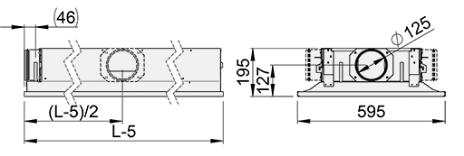
总长 2500 – 3600 mm
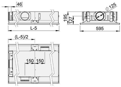
注:对于较低型号(最小145mm),请联系销售人员。
| 线圈长度 | 900, +100, …, 3300 |
| L-5 | 1195, +100, …, 3595 (+1715) |
| Weight (kg/m) | 14 |
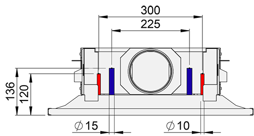
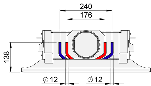
盘管尺寸
正常效率 (CE=N)
单回路高效线圈 (CE=H1)
高效线圈,双回路 (CE=H2)
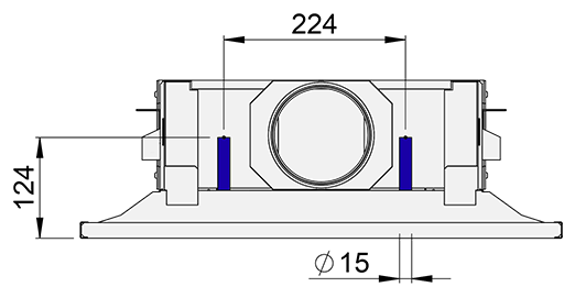
标准,制冷 (CE=S)
标准,制冷,低压降 (CE=SL)
标准,制冷和制热 (CE=SH)
带集成排气型号 (EX=A)
与吊顶集成
材料
| 部件 | 材料 | 表面处理 | 备注 |
| 前面板 | 预涂镀锌钢 | 聚酯漆、白色(RAL 9003 或 RAL 9010,20% 光泽度) | 提供特殊颜色 聚酯-环氧涂漆 |
| 侧板 | 预涂镀锌钢 | 聚酯漆、白色(RAL 9003 或 RAL 9010,20% 光泽度) | 提供特殊颜色 聚酯-环氧涂漆 |
| 底板 | 镀锌钢 | 聚酯-环氧树脂-涂漆、 白色 (RAL 9003 或 RAL 9010,20% 光泽度) |
提供特殊颜色 |
| 送风管道 | 镀锌钢 | ||
| 支架 | 镀锌钢 | ||
| 盘管 | 铜 | ||
| 盘管翅片 | 铝 | ||
| 排气阀 | 镀锌钢 | 聚酯-环氧树脂-涂漆、 白色 (RAL 9003,30% 光泽度) |
参见 Halton URH 阀门 125 mm |
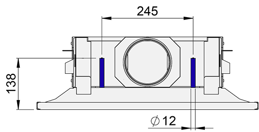
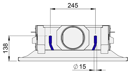
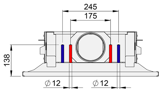
制冷/制热水管接口为 Cu15/Cu12/Cu10,壁厚为 0.9-1.0 mm,符合欧洲标准 EN 1057:1996。
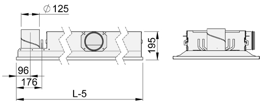
冷水/热水回路的最大工作压力为 1.0 MPa。送风管道接口为 125 mm。
附件
| 附件/选项 | 代码 | 描述 | 备注 |
| 组合式冷热盘管 | TC=H | 带热水循环的盘管 | 冷却/加热铜质水管接口直径为 15/10 或 12 mm(参见尺寸部分)。 |
| 浩盾空气质量控制(HAQ 风闸) | AQ=A | 手动操作 | |
| AQ=B | 电动操作。 电源: 24 VAC。 控制信号: 0 … 10 VDC |
||
| AQ=R | 改造 | ||
| 集成式排气阀 | EX=A | 位于冷梁前端的集成排气阀 | |
| 卡入式天花板安装适配器 (Dampa) |
IO=DC | 卡入式天花板内安装 | 可提供量身定制的解决方案 |
线圈有效长度
| 附件选项 | 代码 | 线圈有效长度 |
| 不带 HAQ | AQ=N | L – 200 mm |
| 带 HAQ | AQ=A,B,R | L – 300 mm |
| 不带 HAQ, 带 URH | AQ=N;EX=A | L – 300 mm |
| 带 HAQ 和 URH | AQ=A,B,R; EX=A | L – 500 mm |
排气阀集成
浩盾Rex 600 冷梁可配备集成排气阀,在同一装置中提供送风和排风。集成排气阀可将有效长度减至总长度 500 mm(L – 500 mm)(适用于标准冷梁 L-300)。
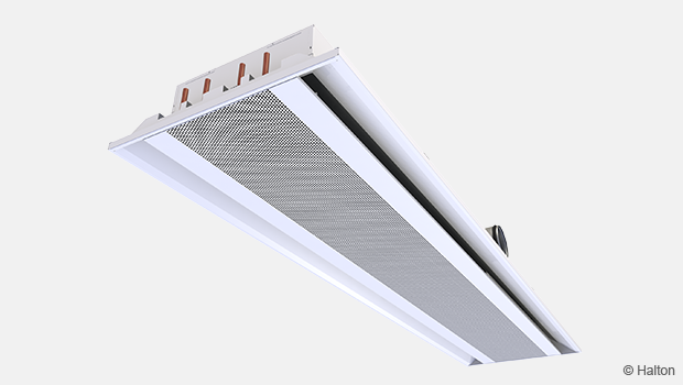
功能
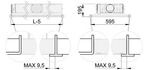
浩盾 Rex 600 冷梁可与吊顶齐平安装。
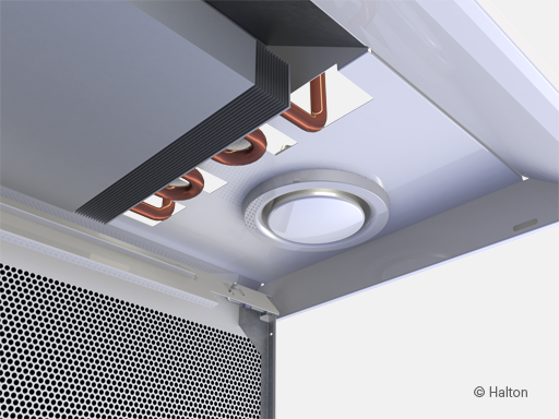
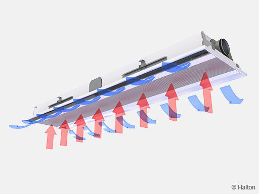
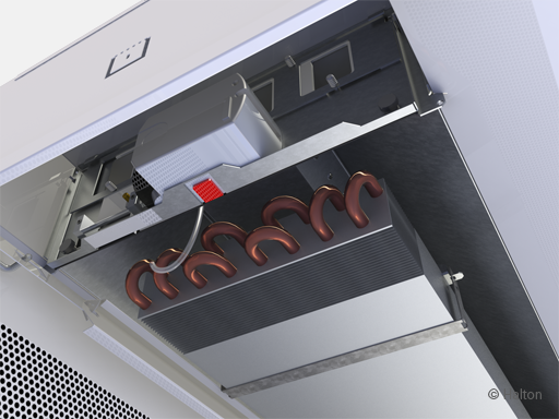
主要送风进入主动式冷梁静压箱。通过喷嘴和 HAQ 控制器的散流器将空气分配到室内。送风槽位于横梁底部。
送风喷嘴可有效地诱导室内空气。诱导空气流经热交换器,在那里被冷却或加热。
送风喷嘴沿天花板表面水平喷射。
占用区域的风速控制
浩盾风速控制(HVC)用于调整房间的空气流速条件,特别是在房间布局发生变化时(例如,当隔断墙靠近冷梁时)或需要改变局部、个人的风速条件时。HVC 的调整会影响通过热交换器诱导的房间气流,因此,它会增加或减少占用区域的风速以及冷梁的冷却/加热能力。
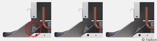
Pos.1 = 节流位置 Pos.2 = 正常位置 Pos.3 = 增压位置
HVC 风门分为几个部分(Pos.1-3),以便调节占用区域不同部分的条件。
建议将冷梁设计在正常位置,以便在建筑生命周期内同时实现节流和增压功能。
风量控制
冷梁喷嘴的送风量取决于有效长度和静压室压力,可通过单独的气流调节风闸进行调节。
可选的浩盾空气质量控制(HAQ)用于调节和/或控制室内空间的室外空气流速。空气流速取决于控制风门的开启位置和静压室压力。
当空间用途发生变化,需要调整送风量时,就需要对空气流速进行调节。可根据需求,通过电动控制风闸手动或自动调节空气流量。
装有 HAQ 手动风量调节装置的冷梁可改装为电动型,以便根据需求进行通风。
在下列情况下,建议将用于按需调节气流的冷梁连接到恒压管道区
- HAQ 调节对喷嘴喷射气流没有影响
- HAQ 调节对盘管冷却或加热能力均无影响
- HAQ 气流控制对管道系统的压力条件和同一管道系统区域内其他冷梁的气流速率没有重大影响。
恒定气流、可调气流或可变气流的不同设备外观相同。
通过浩盾空气质量控制单元的位置和冷梁喷嘴尺寸的选择,可以调节空间内的主要空气流速。安装在管道支管上的独立气流调节风闸用于平衡管道系统中的气流。
当使用电动空气质量控制(HAQ)装置时,最大和最小空气流量可通过风闸的行程限制器进行调节。
在安装和调试过程中,可使用浩盾空气质量控制装置调节每根横梁的主要空气流速。无需更换或堵塞冷梁的喷嘴。
空气质量和温度控制
根据室温控制器的控制信号,通过调节水流量来控制冷梁的制冷和制热能力。
当通过调节水流量单独控制室内空气温度时,可使用二氧化碳传感器等设备对室内空间进行空气质量控制。或者,也可以使用温度传感器进行空气质量控制,在第一序列中调节空气流量,如果温度超过设定点,则在第二序列中开始打开水阀。
在加热模式下,建议喷气出口与室内空气的温差不超过 3 °C。热交换器的进水温度不应高于 35 °C。最佳的加热性能需要适当的一次空气流量。因此,空气处理机组应在供暖期间运行,以确保适当的供暖性能。
安装
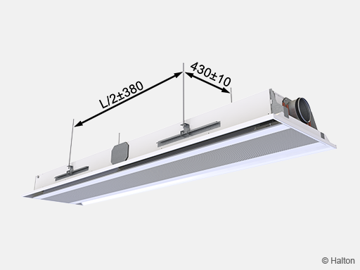
Halton Rex 600 可调节冷梁特别适合安装在天花板上,与房间外墙平行。在选择冷梁方向时,要考虑到送风和水路连接的位置。
冷梁可以直接安装在天花板表面(H1 = 195 mm),也可以使用螺纹连接杆(8 mm)悬挂。每根横梁都配有固定在横梁两侧的活动支架。建议将支架放置在距离梁端四分之一长度(L/4)的位置。
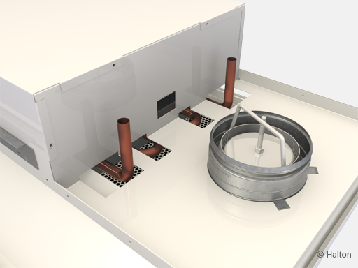
将冷却水和加热水回路的主要管道安装在冷梁水平面以上,以便管道通风。
风管接口与管道接口位于冷梁的同一端。只需使用螺丝刀,就可以在现场轻松地将管道连接处移至冷梁的两侧。
可选的排气阀安装在前部。只能连接左右两个送风管道。选择排气阀选项后,有效长度为总长度 (L) – 500 mm。
排气阀的管道安装
用电动 HAQ 取代手动 HAQ
电源: 24 VAC.
控制信号: 0 … 10 VDC
调节
冷却
建议的冷却水质量流量为 0.02 – 0.10 kg/s,导致热交换器中的温度上升 1 – 4 °C。为避免冷凝,建议热交换器的进水温度为 14 – 16 °C。
加热
建议加热水的质量流量为 0.01 – 0.04 kg/s,导致热交换器中的温度下降 5 – 15 °C。
热交换器进水的最高温度为 35 °C。
平衡和控制水流量
通过安装在冷却水和加热水回路出口侧的调节阀来平衡冷梁的水流量。通过调节水流量来控制冷梁的制冷量和制热量。水流量可通过 ON/OFF 阀或二通或三通比例阀来控制。
调节送风量
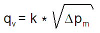
在测量龙头上连接压力计,测量冷梁中的静压。风量按下式计算。
总风量 (qv)

qv 总风量, l/s or m3/h
qv1 喷嘴喷射风量, l/s or m3/h
qv2 空气质量控制散流器(HAQ) 风量, l/s or m3/h
喷嘴喷射风量 (qv1)

l eff 线圈长度 [m]
Δpm 测量的静压室压力[Pa]
| 喷嘴 | k (l/s) | k (m3/h) |
| A | 0.71 | 2.56 |
| B | 0,99 | 3,56 |
| C | 1,36 | 4,90 |
| D | 2.09 | 7,52 |
| E | 3,33 | 11,99 |
空气质量控制散流器风量(qv2)
.png)

a HAQ 位置
Δpm 测量的静压室压力 [Pa]
| k (l/s) | k (m3/h) |
| 0.17 | 0.61 |
恒定气流应用中的气流调节
以毫米为单位确定 HAQ 的位置,该位置与实际腔室压力水平下的气流速率相对应。
HAQ 的调节可借助位置标尺,通过调节装置的开口手动完成。可以在位置标尺上确认以毫米为单位的开口。
为确保精确调节,建议在调节 HAQ 位置的同时使用压力计读取目标腔室压力。
也可以打开两个滚花螺丝 (4),将 HAQ 单元从框架上卸下,以便进行调整。
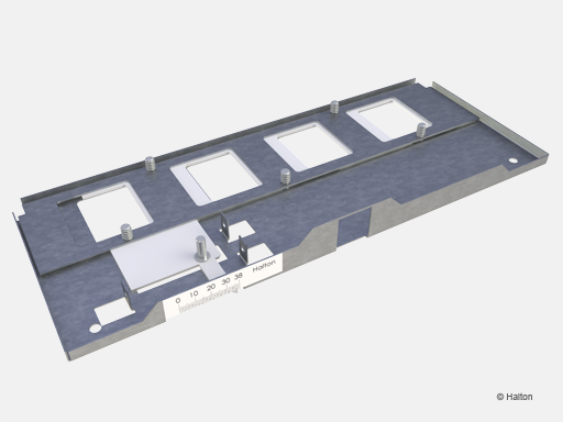
Fig.1. 浩盾空气质量控制 (HAQ), 手动
在变气流应用中调节气流范围
关闭执行机构的电源。
松开旋钮 (1),使执行机构齿轮脱开,进入手动超控位置。
确定最大和最小位置,以毫米为单位,对应实际腔室压力水平下的最大和最小气流速率。
最大和最小位置通过两个内六角固定螺钉 (2,3) 进行调节。可以在位置刻度上确认以毫米为单位的开度。
接通执行机构的电源(24 VAC)。执行机构根据设定的极限值自动校准最小和最大位置。
从此时开始,可以通过 0…10VDC 控制信号来控制执行机构(0 VDC = 最小位置,10 VDC = 最大位置)。
还可以通过打开两个滚花螺钉 (4) 将 HAQ 单元从框架上卸下,以便进行调整。
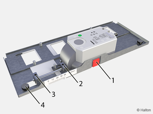
Fig.2. 浩盾空气质量控制 (HAQ), 机动的
图例
1. 释放执行器
2. 最大开度限制
3. 最小开口限制
4. 滚头螺钉(2个)
调节排风量
通过旋转中心锥调节阀门。测量 (A) 中央锥体的开启位置(mm)。浩盾提供一种特殊工具,用于精确测量开启位置。在阀门内设置一个压力探头,用压力计测量压差。使用下表中的 k 系数,按下式计算气流率。调节后,用锁紧螺母锁紧中心锥体。
| URH 125 | |
| A | k |
| -15 | 0,65 |
| -12 | 0,92 |
| -9 | 1,22 |
| -6 | 1,53 |
| -3 | 1,84 |
| 0 | 2,17 |
| 3 | 2,52 |
| 6 | 2,83 |
| 9 | 3,14 |
| 12 | 3,46 |
| 15 | 3,77 |
保养
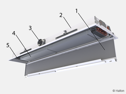
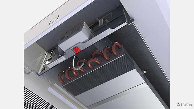
代码描述:
1. 前面板
2. 侧板
3. 送风接口
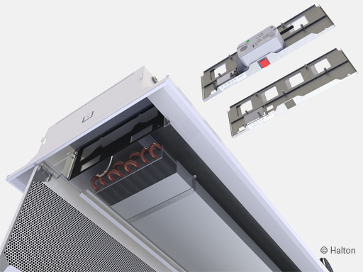
4. 热交换器
5. 浩盾空气质量控制 (HAQ)
打开送风口、管道系统和热交换器的前面板。对于长度超过 2400 mm的冷梁,前面板可分两部分打开。
用真空吸尘器清洁送风管道和热交换器的翅片盘管,注意不要损坏翅片盘管。
用湿布清洁前面板,必要时清洁侧板。
浩盾空气质量控制单元 (HAQ) 可拆卸,以便清洁箱体。拧下螺钉即可拆下 HAQ。
规格
主动式冷梁通过其穿孔前面板具有一个集成的再循环空气通道。通过三个设定位置可手动调节诱导室内空气流量,而不会影响主送风量。冷梁的气流量可在不堵塞或更换喷嘴的情况下进行调节。
主送风量可通过集成在冷梁中的送风单元在较大范围内进行调节。在保持静压室压力恒定(可选)的情况下,气流量的调节不会影响通过盘管的诱导空气流量。
配备有手动可调气流风闸的冷梁装置应能够改装为电动气流控制风闸装置。
室外空气流量控制不应影响盘管的制冷和制热能力。
具有可调气流量的冷梁应只有一个风道连接。
恒定气流和可变气流率的冷梁外观应相同。
前面板应从两侧均可打开,以便进行一般维护和清洁。
前面板应可在不使用任何特殊工具的情况下拆除
向室内空间的送风应为单向或双向。
主动式冷梁的宽度应为595mm,高度应为195mm。
主动式冷梁的进风道直径为125mm。
风道连接的位置应可在不使用任何特殊工具的情况下进行更改。
框架、前面板和侧面板应由镀锌钢板制成。
所有可见部件应为白色,按照RAL 9003或RAL 9010(20%光泽度)进行涂装。
所有管道应由铜制成,连接管道的壁厚为0.9-1.0mm。
翅片应由铝制成。
可选项,可通过两个串联连接的10mm管道在热交换器内实现加热。
所有接头均应焊接,并在工厂进行压力测试。
管道系统的最大工作压力为1.0 MPa。
主动式冷梁可选配气流调节风闸和测量接头,以便测量气流。
作为可选项,排气阀应集成在冷梁中。
主动式冷梁应用可拆卸的塑料涂层进行保护,并单独用塑料包裹。
在运输过程中,风道连接和管道末端应保持密封。
主动式冷梁应通过粘贴在冷梁和塑料包装上的标签进行标识。
订购代码
RE6-S-L-C-E, TC-CE-CO-AQ-EX-ZT
S = Nozzle type
A Bi-directional / Nozzle 1
B Bi-directional / Nozzle 2
C Bi-directional / Nozzle 3
D Bi-directional / Nozzle 4
E Bi-directional / Nozzle 5
L = Total length
1200,+100,..,3600 (and 1720)
C = Effective length (Cooling coil length)
(See in Accessories tab table of effective length of coil
with different accessories and product options)
900,+100,..,3400
E = Duct connection / Duct size / Damper
R2N Right / 125 / Without damper
L2N Left / 125 / Without damper
S2N Straight / 125 / Without damper
Other Options and Accessories
TC = Cooling /Heating functions (Coil type)
C Cooling
H Cooling and Heating
CE = Coil efficiency
N Normal
H1 High efficiency (single loop)
H2 High efficiency (twin loop)
S Standard, cooling
SL Standard, cooling, low pressure drop
SH Standard, cooling and heating
CO = Colour
SW Signal white (RAL9003)
W Pure white (RAL 9010)
X Special colour (RALxxxx)
AQ = Air quality control (HAQ)
A Manual
B Motorised
R Retrofit
EX = Exhaust
N No
A URH
ZT = Tailored product
N No
Y Yes (ETO)
Code example
RE6-A-3000-2700-R2N, TC=C,CE=N,CO=SW,AQ=A,EX=N,ZT=N
Downloads
"*" indicates required fields