Product / HMM
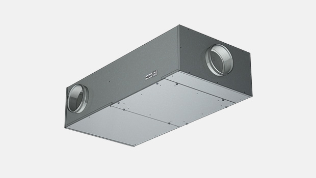
HMM单管布风器
浩盾 HMM 是应用于单管道的手动调节式布风器。


概述
- 压力范围 50 Pa 到 1000 Pa
- 气流范围 0 m3/h 到 500 m3/h
- 通过散流器旋钮调节气流
- 机械设定最大/最小气流限制,易于调试
- 流量测量管
- 获得 MED 认证的 B-0 和 B-15 安装等级
加热模式的其它特点
- 230 VAC 610%,最大10A,50/60 Hz
- 双向可控硅控制加热线圈,可调节加热功率 (PWM) 0…100%
- 主/辅功能:多个辅助布风器可以连接到一个主布风器上
- 内部熔断丝 8A 或 10A 和 63 mA
- 网络与适配器兼容
- 所有参数可在工厂预设或在调试时通过 PDA 现场设定
- 所有电缆连接均带快速接头
- 适合不同安装需要
- 带状态检测指示和手动复位的 90°C 安全开关
- HMM 布风器可配备控制板和互连电缆
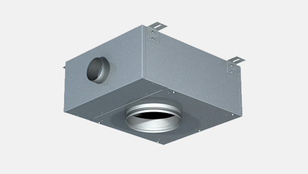
尺寸
HMM 尺寸

HMM 尺寸, 设备材料尺寸 0,5 mm,芬兰拉赫蒂工厂生产
| L | B | H | ØD1 male/female | ØD2 male | |
| HMM-100 | 590 | 490 | 190 | 199/201 | 99 |
| HMM-125 | 590 | 490 | 230 | 249/251 | 124 |
注:公接头:外径尺寸,母接头:内径尺寸。对于进气口尺寸为80或160,出气口尺寸为160、200或250的特殊情况,可提供特殊尺寸。
对于特殊尺寸的接头,其声学和压降数据较为有限。
HMM 尺寸, 设备材料尺寸 0,75/1,0 mm,中国上海工厂生产
| L | B | H | ØD1 male/female | ØD2 male | |
| HMM-100 | 600 | 500 | 200 | 199/201 | 99 |
| HMM-125 | 600 | 500 | 240 | 249/251 | 124 |
注:公接头:外径尺寸,母接头:内径尺寸。对于进气口尺寸为80或160,出气口尺寸为160、200或250的特殊情况,我们提供特殊尺寸的接头。
对于特殊尺寸的接头,其声学和压降数据较为有限。
材料
| 部件 | 材料 |
| 箱体 | 热镀锌钢或可选配EN 1.4404(AISI316L)不锈钢 |
| 箱体厚度 | 0,5 mm或 0,75/1,0 |
| 风管接口 | 热镀锌和EPDM橡胶或可选配不锈钢EN 1.4404 (AISI316L) |
| 隔热层 | 矿物棉 s = 20 mm, MED 认证(芬兰拉赫蒂)或 岩棉 s =25 mm(中国上海) |
| 信号控制器 | 铝/塑料/电器元件 |
| 加热线圈 | EN 1.4301 (AISI304) |
| 电缆 | 无卤 |
| 测量管 | 铝/聚氨酯 |
产品型号和附件
HMM 产品型号
- 不带加热器的手动布风器
- 带加热器的手动布风器
- 网络支持与适配器兼容。作为D03控制包的选项之一可供选择。
控制板特点
浩盾船舶HMM 布风器有三种不同的控制板型号; 旋转按钮、带LED条形图的按钮 (可选配: IP54) 、带LCD显示器的按钮 (可选配: IP54).
一般功能
- 舱房温度测量
- 蓝牙/通信适配器连接器,用于设置舱房参数
- 参数设置和故障排除软件
- 不同的颜色选项和自定义标签可供选择
- 随IC电缆(互连电缆)交付
- 用于控制面板-布风器连接
- 两端用塞子预制
- 可以通过标准安装管拔出面板一侧的电缆插口
- 无卤且阻燃
- 标准长度为7米,可选配其他长度
带旋转按钮的控制板
- 通过旋转按钮调节温度
带按钮和LED条形图的控制板
- 通过按钮调节温度
- 自检功能
- LED亮度控制和自动调光
带按钮和LCD显示屏的控制板
- 通过按钮调节温度
- 自诊断功能
- LCD亮度控制和自动调光
- 可选配显示实际温度和设定点温度
- 可选配时间显示
- 可选配客户定制的背景图片
- 可选配多种外框
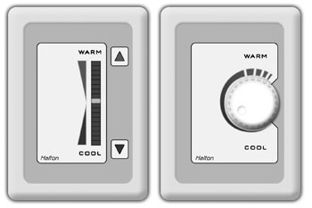
控制板型号:按钮和旋转按钮
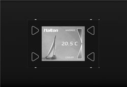
LCD 控制板
布风器通风配置表
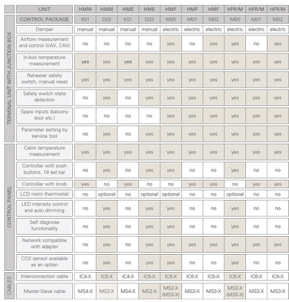
请注意:还可选配不带成套控制设备的HMM和HME型号。
手动控制风量
单管道型号; HMM, HME
压力相关型号
单管道型号: HMF, HFM
压力无关型号
单管道型号; HMF, HFM
附件
MS-线缆 (主辅线缆)
- 用于主布风器——辅布风器/装置链接
- 两端预置插口
- 无卤且阻燃
- 标准长度为7米
通讯适配器
- 与外部设备的蓝牙通信(仅适用于D03控制包)
- 用于无线连接以设置布风器参数和故障排除(仅适用于D03控制包)
网络适配器 (可与D03控制包一起使用)
- 网络适配器(也可用作WiFi)将独立布风器扩展为网络兼容装置(LON或以太网)
- 实现监测和高级能效功能。
- 有关更多信息,请参阅Halton Networks的舱房通风手册或联系Halton Marine销售办事处。
可选加热器
- 标准加热器: 400W, 800W, 1200W, 1500W 带K01控制包
- 标准加热器: 400W, 800W, 1200W, 1500W, 1800W带D03控制包
实际功率水平可以逐个布风器软件调整。电缆和电源设计必须根据最大可用加热功率进行。
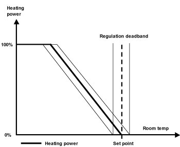
功能
气流通过预设限制之间的调节旋钮进行控制。
带加热器型号
当乘客使用控制面板要求更高的温度时,控制器会激活布风器的电再热器。当舱房内达到所需温度时,将保持参考值,直到温度需求发生变化。
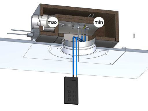
机械最大和最小限值在调试期间设置。
加热器调节图
HMM 不带加热器的运行范围
| HMM-100 | HMM-125 | HMM-160 |
| 0 m3/h – 350 m3/h | 0 m3/h – 500 m3/h | 0 m3/h – 500 m3/h |
HMM带加热器的运行范围
| HMM-100 | HMM-125 | HMM-160 |
| 100 m3/h – 350 m3/h | 100 m3/h – 500 m3/h | 100 m3/h – 500 m3/h |
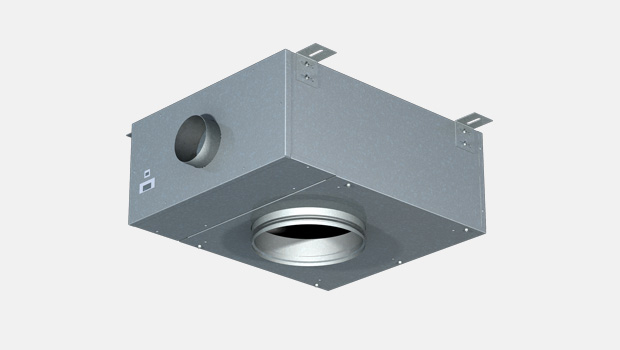
安装
布风器安装说明
在设计安装时,应考虑项目要求和可能性。有关可能性的更多信息,请联系浩盾船舶。
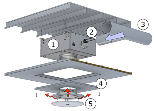
布风器安装的主要原则:
1. 使用螺纹杆(如图所示)或框架安装将布风器固定在天花板上方
2. 将电源和IC电缆连接到设备。(电缆安装应在此阶段之前完成,请参阅互连电缆安装说明)。由于标准布风器具有Ensto NAC 31电源插头(不包括对应的NAC 32)。
3. 连接送风管道至布风器进气口。
4. 关闭维护/安装检修门。
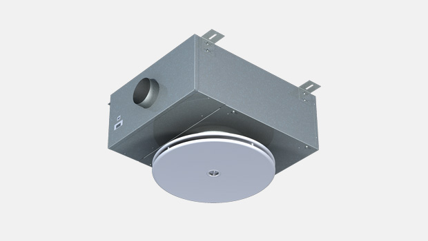
5. 将散流器连接并组装到风气出气口。
控制面板安装说明
1. 将LRC-1 CP背板安装到墙上的平整位置。
2. 拧紧3个螺钉(DIN 7981或类似标准,Φ3mm,最大头部高度3mm),将CP固定到位。
3. 将LRC-1互连电缆连接到互连连接器。最大允许牵引力为30N。
4. 将LRC-1 CP前板安装到背板上
5. 小心地拧紧底部的螺钉。最大扭矩0.3 Nm
LRC-1 CP装置应放置在其调节的房间内的墙上。建议避免阳光直射或靠近加热/冷却源物体
通讯电缆安装说明
互连线缆已预先在两端安装了插头。安装时,需将其穿过提供的管子,从布风器拉至CP(CP的插头尺寸足够小,可以穿过直径为16毫米的管子)。最大允许牵引力为30N。在CP一侧的房间内,需将大约8厘米的线缆(电线)留在管子外部。管子靠近的一端(即CP侧)必须封堵(例如使用泡沫),以防止冷凝水和热量传递至CP。
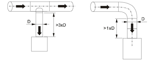
安全距离
安装布风器时,必须考虑所示的所需安全距离。
调节
送风量是通过使用测量探头和压力计来确定的。
散流器前板被拆除,管子穿过散流器。用压力计测量压差。风量使用以下公式计算。
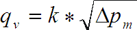
qv = 风量 (m3/h)
k = k 系数
∆pM = 测量压力 (Pa)
K-系数表格
| NS | k |
| HMM-100 | 48,2 |
| HMM-125 | 74,2 |
通过旋转D形杆调整最小风量,直到达到所需的设置。
将最小气流机械限制器移到支架上,并拧紧内六角螺钉。
通过旋转D形杆调整最大风量,直到达到所需的设置。
将最大气流机械限制器移到支架上,并拧紧内六角螺钉。
调试
调试(适用于D03)
所有参数均可根据订单在工厂预设。在调试期间,可以使用LRC管理器软件通过PDA手持设备无线修改所有参数。
浩盾还为这些项目提供监管和调试服务。
如需更多信息,请联系浩盾船舶销售办公室。
重量
| 箱体厚度 | HMM-100 | HMM-125 | HMM-160 |
| 0,5 mm | 10,5 | 11,5 | 12 |
| 0,75/1,0 mm | 15 | 16 | 16,5 |
加热器 + 信号控制器 +1kg
产品代码
HMM product code
| HMM ver 3 | |||||||||
| (S)=Model | |||||||||
| (M) No reheater | |||||||||
| (R) Electric reheater | |||||||||
| (C)=Diameter of inlet connection | |||||||||
| 125 | |||||||||
| 100 | |||||||||
| 80 | |||||||||
| (E.)=Diameter of outlet connection | |||||||||
| 160 | |||||||||
| 200 | |||||||||
| 250 | |||||||||
| (C2)=Outlet connection type | |||||||||
| (A) Male with gasket | |||||||||
| (B) Male without gasket | |||||||||
| (C.) Female | |||||||||
| (CP)=Location of Power Supply Connection | |||||||||
| (F) Front end | |||||||||
| (S) Side | |||||||||
| (NA) No PS connection | |||||||||
| (CU)=Control Unit | |||||||||
| (K1) K01 (Knob, master) | |||||||||
| (K2) K01 (Knob, slave) | |||||||||
| (D1) D03 (Push button) | |||||||||
| (NA) No control unit | |||||||||
| (RH)=Reheat Coil | |||||||||
| (NA) No reheater | |||||||||
| (S1) Single coil 400 W | |||||||||
| (S2) Single coil 800 W | |||||||||
| (S3) Single coil 1200 W | |||||||||
| (S4) Single coil 1500 W | |||||||||
| (S5) Single coil 1800 W | |||||||||
| (ZT)=ETO Processing | |||||||||
| (Y) Yes | |||||||||
| (N) No | |||||||||
| AC=Accessories | |||||||||
| Code example | |||||||||
| HMM/R-80-250,C2=A,CP=F,CU=D1,RH=S1,ZT=Y | |||||||||
噪音衰减
噪音衰减(dB)
| f(Hz) | 63 | 125 | 250 | 500 | 1000 | 2000 | 4000 | 8000 | |
| HMM-100 | ∆L(dB) | 6,4 | 11,3 | 15,9 | 25,8 | 34,8 | 37,9 | 35,3 | 34,7 |
| HMM-125 | ∆L(dB) | 4,9 | 9,6 | 16,2 | 24,9 | 33,4 | 36,8 | 35,4 | 35,6 |
∆L: 噪音衰减不包含底端反射
Downloads
"*" indicates required fields