Product / HMM
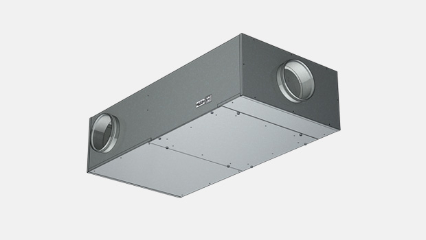
HMM – Single duct cabin unit
Halton HMM is a manually operated cabin unit for single duct applications.
Overview
- Pressure range from 50 Pa up to 1000 Pa
- Airflow range 0 m3/h…500 m3/h
- Airflow adjustment with diffuser knob
- Mechanical max./min. airflow limits for easy commissioning
- Airflow measurement probes
- MED approved for B-0 and B-15 installations
Additional features with reheat models
- 230 VAC ±10%, 50/60 Hz
- Triac controlled reheating coil(s), adjustable heating power (PWM) 0…100%
- Master/slave functionality: several cabin units can be controlled by one control panel
- Internal fuses included
- All parameters can be set onsite during commissioning by external device or preset at the factory
- All cable connections with fast connectors
- Easily tailored for different types of installations
- 90°C safety switch with state detection and manual reset
- HMM cabin unit is supplied with control panel and interconnection cable
Specification
Halton HMM is a manually operated cabin unit for single duct applications. Airflow is controlled via an adjusting knob installed on the diffuser. The control mechanism has mechanical limits for minimum and maximum airflows. These limits can be easily set during commissioning. HMM is recommended to be used in conjunction with Halton’s diffusers, as the mechanism has to be fixed to the diffuser’s structure. The airflow is adjusted with diffuser knob. The HMM cabin unit can be supplied with reheater – controlled by a control panel.
Dimensions and Weight

Unit material thickness 0.5 mm from Lahti, Finland
| L | B | H | A | ØD1 male/female | ØD2 male | |
| HMM-100 | 590 | 490 | 190 | 45 | 199/201 | 99 |
| HMM-125 | 590 | 490 | 230 | 45 | 249/251 | 124 |
| HMM-160 | 590 | 490 | 230 | 45 | 249/251 | 159 |
Note: male connection: outer dimension, female connection: inner dimensions. Special dimensions available for inlet 80 or 160 and outlet 160, 200 or 250.
Sound and pressure drop data is limited for special dimensions.
Unit material thickness 0.75/1.0 mm from Shanghai, China
| L | B | H | A | ØD1 male/female | ØD2 male | |
| HMM-100 | 600 | 500 | 200 | 40 | 199/201 | 99 |
| HMM-125 | 600 | 500 | 240 | 40 | 249/251 | 124 |
| HMM-160 | 600 | 500 | 240 | 40 | 249/251 | 159 |
Note: male connection: outer dimension, female connection: inner dimensions. Special dimensions available for inlet 80 or 160 and outlet 160, 200 or 250.
Sound and pressure drop data is limited for special dimensions.
Weight
| Casing thickness | HMM-100 | HMM-125 | HMM-160 |
| 0.5 mm | 10.5 | 11.5 | 12 |
| 0.75/1.0 mm | 15 | 16 | 16.5 |
Reheater + I/O unit +1kg
Material
| PART | MATERIAL |
| Casing | Hot galvanized steel or EN 1.4404 (AISI316L) as an option |
| Casing thickness | 0.5 mm from Lahti, Finland or 0.75/1.0 mm from Shanghai, China |
| Spigots | Hot galvanized steel and EPDM rubber or EN 1.4404 (AISI316L) as an option |
| Insulation | Mineral wool, s = 20 mm, MED approved from Lahti, Finland or Rock wool, s=25 mm from Shanghai, China |
| Input/output unit | Aluminium/plastic/electronics |
| Reheat coil | EN 1.4301 (AISI304) |
| Cables | Halogen free |
| Airflow measurement probes and tubes | Aluminium/polyurethane |
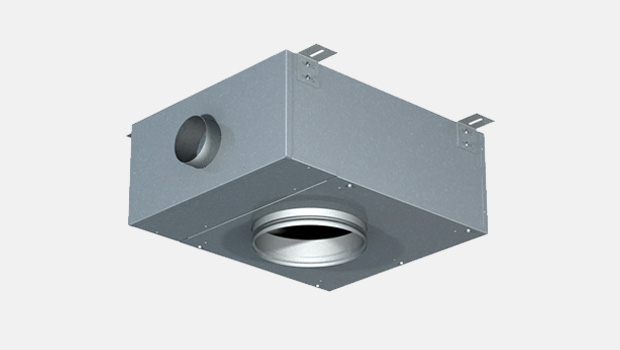
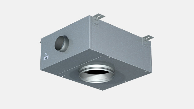
Product Models
Product options
- Manual cabin unit without reheater
- Manual cabin unit with reheater
- Network compatible with adapter. Available as an option with D03 control package.
Available reheaters
- Standard reheaters: 400W, 800W, 1200W, 1500W with K01 control package
- Standard reheaters: 400W, 800W, 1200W, 1500W, 1800W with D03 control package
Practical power level may be software adjusted cabin by cabin. Cable and power supply design has to be done according to maximum available heating power.
Control panel features
Halton Marine HMM cabin units are available with three different control panel models; with rotating knob, push buttons with LED bar graph (available as option: IP54) and push buttons with LCD-display (available as option: IP54).
Common features
- Cabin temperature measurement
- Connector for bluetooth / communication adapter to set cabin parameters
- Software for parameter setting and trouble shooting
- Different colour options and custom labeling available as an option
- Delivered with IC-Cable (interconnection cable)
- For control panel – cabin unit connection
- Prefabricated with plugs on both ends
- Cable plug on panel side is designed to be pulled through standard installation pipe
- Halogen free and flame-retardant
- Standard length 7 meters. Other lengths available.
Control panel with rotating knob
- Temperature adjustment by rotating knob
Control panel with push buttons and LED bar graph
- Temperature adjustment by push buttons
- Self diognose function
- LED intensity control and auto dimming
Control panel with push buttons and LCD-display
- Temperature adjustment by buttons
- Self diagnose function
- LCD intensity control and auto dimming
- Display for actual and set point temperatures available as an option
- Time display available as an option
- A customized background picture available as an option
- Several frame options available
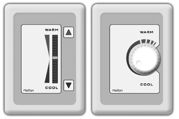
Control panel models; push buttons and rotating knob
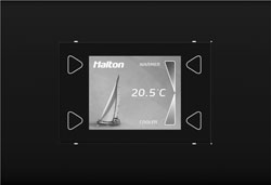
LCD control panel
Cabin ventilation configuration table
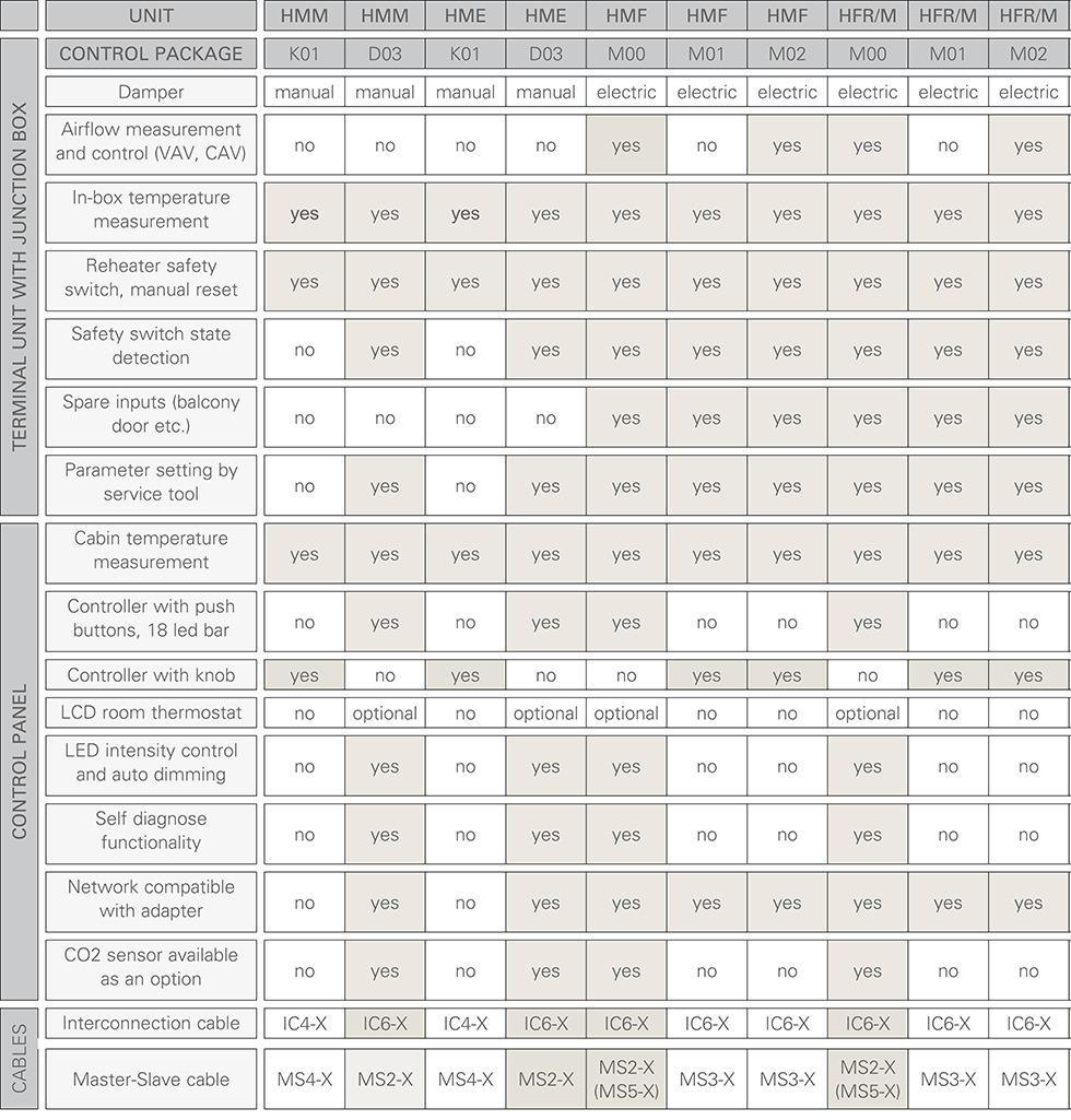
Please note: HMM and HME units are also available without a control package.
Manually controlled airflows
Single duct units; HMM, HME
Pressure dependent units
Single duct units: HMF, HFR/M
Pressure independent units
Single duct units; HMF, HFR/M
Accessories
MS-Cable (master-slave cable)
- For master cabin unit – slave cabin unit/units connection
- Prefabricated with plugs on both sides
- Halogen free and flame-retardant
- Standard length is 7 meters. Other lengths available as an option.
Communication adapter
- Bluetooth communication to external device (only with D03 control package)
- For wireless connection to set cabin unit parameters and trouble shooting (only with D03 control package)
Network adapters (available with D03 control package)
- Network adapter (also available as WiFi) expands a stand-alone unit to network compatible unit (LON or Ethernet network)
- Enables supervision and advanced energy efficiency functions
- For more information, see Halton Networks for cabin ventilation -brochure or contact Halton Marine Sales office.
Function
Airflow is controlled via an adjustment knob between the preset limits.
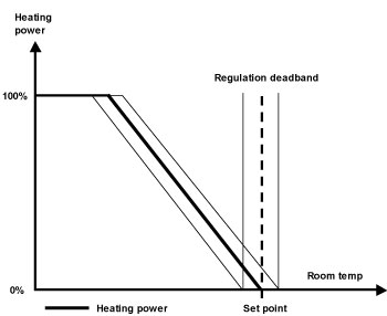
Models with reheater
When passenger demands for warmer temperature by using control panel, the controller activates the electric reheater inside the cabin unit. When the required temperature in the cabin is achieved, the reference is held until the temperature demand changes.
Mechanical maximum and minimum limits are set during commissioning.
Regulation diagram with reheater
Operating range for HMM without reheater
| HMM-100 | HMM-125 | HMM-160 |
| 0 m3/h – 350 m3/h | 0 m3/h – 500 m3/h | 0 m3/h – 500 m3/h |
Operating range for HMM with reheater
| HMM-100 | HMM-125 | HMM-160 |
| 100 m3/h – 350 m3/h | 100 m3/h – 500 m3/h | 100 m3/h – 500 m3/h |
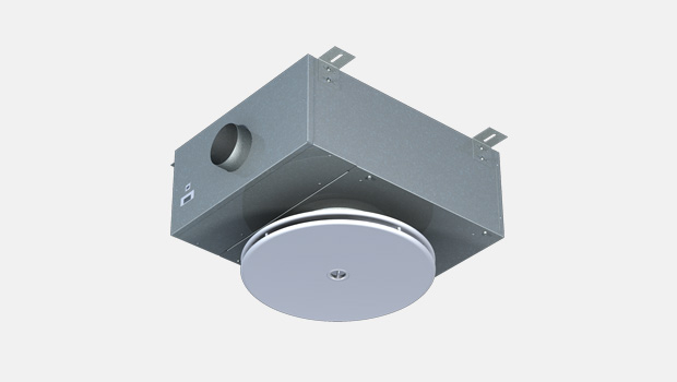
Installation
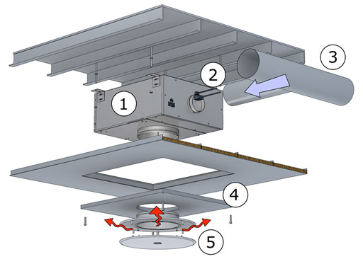
Cabin unit mounting instruction
Projects requirements and possibilities should be taken into account when designing the installation. For more information on the possibilities contact Halton Marine.
Main principles in cabin unit installation:
- Fix cabin unit above false ceiling using thread bar (as seen on picture) or frame installation
- Connect power supply and IC cable to the unit. (cable installation should be done before this phase, see Interconnection Cable Mounting Instructions). As standard cabin unit has Ensto NAC 31 plug for the power supply (counterpart NAC 32 not include).
- Connect supply air ducts to cabin unit inlets.
- Close maintenance / installation hatch.
- Connect and assemble diffuser to the cabin unit outlet.
Control Panel mounting instruction
- Install LRC-1 CP unit back plate to the provided leveled place on the wall.
- Fasten 3 screws (DIN 7981 or similar, Φ3mm, max. head height 3 mm ) to fix CP unit to its place.
- Connect LRC-1 interconnection cable to the interconnection connector. Max. allowed tractive force is 30N.
- Install LRC-1 CP unit front plate to the back plate
- Fasten the screw in the bottom carefully. Max. Torque 0,3 Nm.
The LRC-1 CP unit should be positioned on the wall inside the room it will regulate. It is advised to avoid direct sunlight or position near heating/cooling source object
Interconnection Cable mounting instructions
Interconnection cable comes prefabricated with plugs on both sides. To ins tall, draw it through the provided tube from Cabin unit to CP unit (the plug on CP unit is small enough to allow drawing through Φ16mm tubes). Max. allowed tractive force is 30N. On the CP side, in the room, leave approximately 8 cm of the cable (the wires) outside the tube. The near end of the tube (CP-unit side) must be blocked (e.g. foam) to prevent condensation and thermal transfers reaching CP unit.
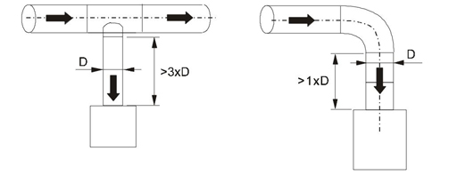
Safety distances
A required safety distance as illustrated must be taken into account when installing the cabin unit.
Adjustment
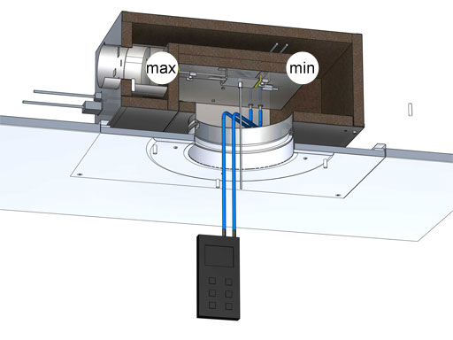
The supply flow rate is determined by using the measurement probes and manometer.
The diffuser front plate are removed and tubes are passed through the diffuser. Measure the differential pressure with a manometer. The flow rate is calculated using the formula below.
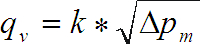
qv = airflow (m3/h)
k = k factor
∆pM = measured pressure (Pa)
K-factors table
| HMM | k |
| HMM-100 | 48.2 |
| HMM-125 | 74.2 |
Adjust the minimum airflow rate by rotating the D-shape bar until the desired setting is achieved.
Move the minimum airflow mechanical limiter against the stand and tighten socket cap screw.
Adjust the maximum airflow rate by rotating the D-shape bar until desired setting is achieved.
Move the maximum airflow mechanical limiter against the stand and tighten socket cap screw.
Commissioning
All parameters can be preset at the factory according to order. During commissioning all parameters can be modified wirelessly with a PDA handheld device using LRC manager software.
Halton also provides supervision and commissioning services for the projects.
For more information contact Halton Marine Sales office.
Product Code
(S)=Model
(M) No reheater
(R) Electric reheater
(C)=Diameter of inlet connection
125
100
80
(E.)=Diameter of outlet connection
160
200
250
(C2)=Outlet connection type
(A) Male with gasket
(B) Male without gasket
(C.) Female
(CP)=Location of Power Supply Connection
(F) Front end
(S) Side
(NA) No PS connection
(CU)=Control Unit
(K1) K01 (Knob, master)
(K2) K01 (Knob, slave)
(D1) D03 (Push button)
(NA) No control unit
(RH)=Reheat Coil
(NA) No reheater
(S1) Single coil 400 W
(S2) Single coil 800 W
(S3) Single coil 1200 W
(S4) Single coil 1500 W
(S5) Single coil 1800 W
(ZT)=ETO Processing
(Y) Yes
(N) No
AC=Accessories
Code example
HMM/R-80-250,C2=A,CP=F,CU=D1,RH=S1,ZT=Y
Sound Attenuation
| f(Hz) | 63 | 125 | 250 | 500 | 1000 | 2000 | 4000 | 8000 | |
| HMM-100 | ∆L(dB) | 6.4 | 11.3 | 15.9 | 25.8 | 34.8 | 37.9 | 35.3 | 34.7 |
| HMM-125 | ∆L(dB) | 4.9 | 9.6 | 16.2 | 24.9 | 33.4 | 36.8 | 35.4 | 35.6 |
∆L: Sound attenuation not including end reflection
Downloads
Request for Quotation
"*" indicates required fields