Product / HFRM
HFRM – Multi-connection cabin unit
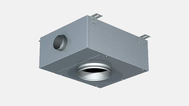
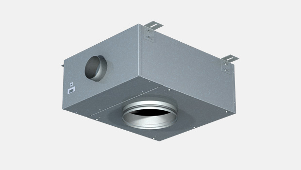
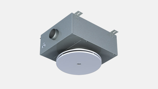
Halton HFR/M is pressure independent or pressure dependent single duct cabin unit with 1-3 outlet connections for terminal units.
Overview
- Pressure range from 200 Pa up to 1000 Pa
- Airflow range 175 m3/h…1000 m3/h
- 230 VAC ±10%, 50/60 Hz
- Inbuilt airflow measurement (pressure independent models)
- Damper min. / max. position settings (pressure dependent models)
- Triac controlled reheating coil(s), adjustable heating power (PWM) 0…100%
- Master/slave functionality: several cabin units can be controlled by one control panel
- Internal fuses included
- All parameters can be set onsite during commissioning by external device or preset at the factory
- All cable connections with fast connectors
- Easily tailored for different types of installations
- 90 °C safety switch with state detection and manual reset
- Minimum flow alarm (pressure independent model) and inbox temperature measurement with overheat limit to cut-off reheater power
- HFR/M cabin unit is supplied with control panel and interconnection cable
Specification
Halton HFR/M is pressure independent or pressure dependent single duct cabin unit with 1-3 outlet connections for terminal units. Pressure independent VAV or CAV operation is facilitated by continuous airflow measurement and damper regulation by intelligent controller. Pressure independent HMF adapts to variations in supply ductwork pressure levels and maintains individual fresh supply airflow rate to each cabin. Pressure dependent VAV operation is facilitated only by damper regulation by intelligent controller. Pressure dependent HMF adapts to room temperature changes by regulating airflow between pre-set minimum and maximum damper positions. Halton HFR/M is an excellent choice for suites, deluxe cabins and office areas where the total airflow needs to be distributed to several points, but controlled centrally with one control panel.
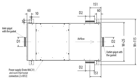
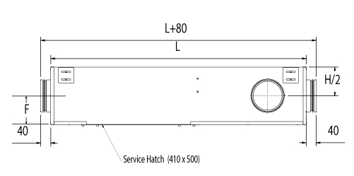
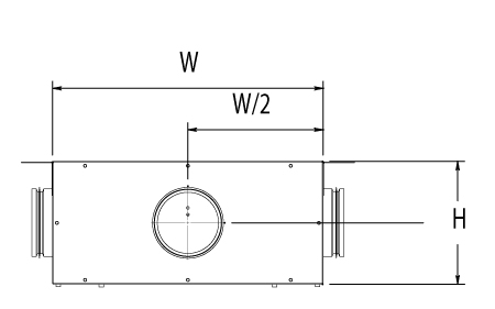
Dimensions
| D1/D2 (DN) | L | W | H | F | |
| HFR/M-125 | 125 | 1000 | 500 | 225 | 99 |
| HFR/M-160 | 160 | 1000 | 500 | 250 | 121 |
| HFR/M-200 | 200 | 1000 | 500 | 300 | 136 |
General drawings
Material and Finishing
| PART | MATERIAL |
| Casing | Hot galvanized steel or EN 1.4404 (AISI316L) as an option |
| Spigots | Hot galvanized steel and EPDM rubber or EN 1.4404 (AISI316L) as an option |
| Insulation | Mineral wool, s = 25 mm, MED approved |
| Input/output unit | Aluminium/plastic/electronics |
| Reheat coil | EN 1.4301 (AISI304) |
| Cables | Halogen-free |
| Airflow measurement probes and tubes | Aluminium/polyurethane |
Product Models
Product options
- Pressure independent model (VAV/CAV)
- Pressure dependent model (VAV)
- Inputs for external switches such as balcony door and key card switches available as an option
- Network compatible with adapter for advanced energy efficiency and supervision system available as an option
- Energy efficiency functions to reduce unnecessary cooling / heating costs available as an option
Control panel features
Halton Marine HMF cabin units are available with three different control panel models; with rotating knob, push buttons with LED bar graph (available as option: IP54) and push buttons with LCD-display (available as option: IP54).
Common features
- Cabin temperature measurement
- Connector for bluetooth / communication adapter to set cabin parameters
- Software for parameter setting and trouble shooting
- Different colour options and custom labeling available as an option
- Delivered with IC-Cable (interconnection cable)
- For control panel – cabin unit connection
- Prefabricated with plugs on both ends
- Cable plug on panel side is designed to be pulled through standard installation pipe
- Halogen free and flame-retardant
- Standard length 7 meters. Other lengths available.
Control panel with rotating knob
- Temperature adjustment by rotating knob
Control panel with push buttons and LED bar graph
- Temperature adjustment by push buttons
- Self diognose function
- LED intensity control and auto dimming
Control panel with push buttons and LCD-display
- Temperature adjustment by buttons
- Self diagnose function
- LCD intensity control and auto dimming
- Display for actual and set point temperatures available as an option
- Time display available as an option
- A customized background picture available as an option
- Several frame options available
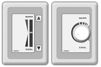
Control panel models; push buttons and rotating knob
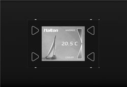
LCD control panel
Cabin ventilation configuration table
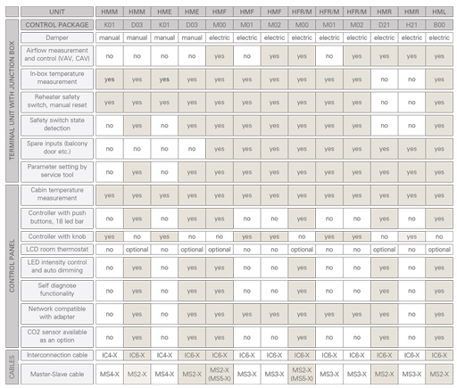
Please note: HMM and HME units are also available without a control package.
Manually controlled airflows
Single duct units; HMM, HME
Pressure dependent units
Single duct units: HMF, HFR/M
Pressure independent units
Single duct units; HMF, HFR/M, HML
Dual duct units; HMR
Downloads
Request for Quotation
"*" indicates required fields