Product / ZRW
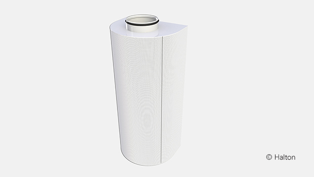
Halton Zen ZRW – 置换通风装置
这种置换式通风设备与墙体结构融为一体,安装起来毫无差别。
- 送风量范围广
- 适合与墙体结构一体化安装
概览
- 送风量范围大
- 通过小孔实现均匀的送风分配,为散流器附近提供最佳条件。
- 在地面水平方向上提供低速空气
- 适合集成安装到墙壁结构中。
- 可拆卸的前板和金属内部结构便于清洁设备和管道系统
- 设备顶部/底部有矩形管道连接。
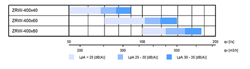
快速选型
尺寸和重量

| NS [mm] |
H [mm] |
H1 [mm] |
K [mm] |
K1 [mm] |
Weight [kg] |
| 400×40 | 800 | 740 | 75 | 38 | 11.1 |
| 400×60 | 1000 | 940 | 92 | 58 | 13.9 |
| 400×80 | 1200 | 1140 | 105 | 78 | 16.6 |
材料
| 部件 | 材料 | 备注 |
| 前端面板 | 镀锌孔板 | – |
| 外壳 | 镀锌 | – |
| 表面处理 | 聚酯环氧漆 白 (RAL 9003/30% gloss) |
可选择特殊颜色 |
功能
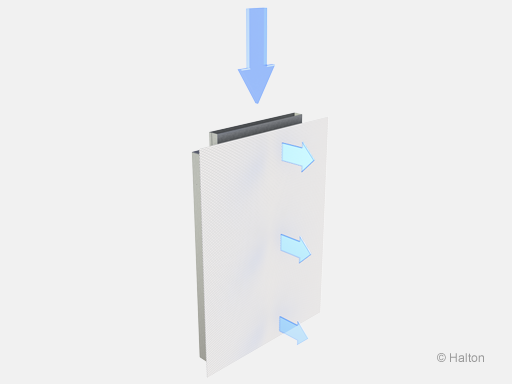
空气通过Halton Zen ZRW的前端面板送入空间,通常其温度略低于室内空气。送风气流下降至地面附近,然后以低速度逐渐弥漫至人员活动区域。最终,由于热表面的对流作用,空气会从人员活动区域上升。低速气流流向前方。
该防堵塞装置易于打开和清洁。
在圆形管道部分,可使用Halton PRA或Halton PTS/C作为气流调节阀。为确保气流测量的可靠性,从置换送风装置到气流调节阀的安全距离应为5倍的管道直径。
如果气流调节阀安装得离置换送风装置较近(最小距离约为3倍的管道直径),送风气流模式将是正确的,但气流测量结果将不准确。当在置换送风装置附近(最小3xD)安装气流调节阀时,可能需要在风阀和置换送风装置之间安装衰减器。
注意:气流模式数据适用于安装在地面附近且与墙壁齐平的装置。
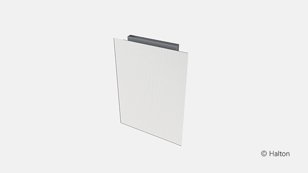
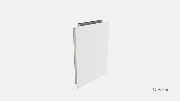
安装
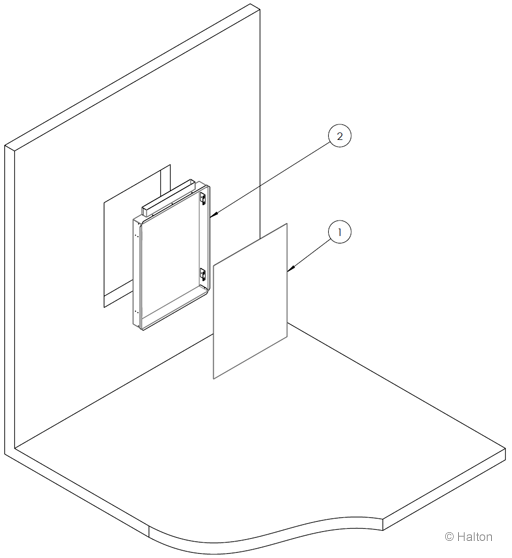
按以下顺序进行安装:
A) 将散流器 (2) 放置在墙壁空间内,并连接管道系统。
B) 用外壳内的螺丝将散流器固定在墙上。
C) 安装散流器前板 (1)。
如果需要安装于天花板(不建议),请联系销售人员。
调整
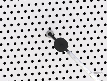
使用压力计测量来自测量接头的压差,从而确定位移装置的送风量。然后用胶带或其他垫片在管嘴内形成密封,以获得准确的读数。
流量的计算公式如下:
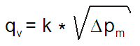
公式中k因子的值
| NS [mm] | k factor |
| 400×40 | 15.2 |
| 400×60 | 21.4 |
| 400×80 | 27.6 |
保养
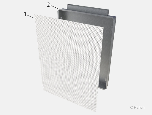
图例
1. 前端面板
2. 外壳
小心拉出弹簧连接,打开前面板 (1)。
用刷子或湿布清洁部件。切勿浸入水中。
按相反顺序重新组装。
规格
Halton Zen ZRW 置换送风装置由镀锌钢制成,涂有标准白色(RAL 9003)聚酯环氧漆。
该设备设计坚固、免维护、无堵塞。
设备由一个可拆卸的穿孔前面板、一个流量均衡板和外壳组成。
根据安装位置的不同,设备顶部或底部有一个矩形管道连接。
订单代码
ZRW-D,CO-ZT
D = Size of duct connection [mm]
400×40, 400×60, 400×80
Other options and accessories
CO = Colour
SW Signal white (RAL 9003)
X Special colour (RAL xxxx)
ZT = Tailored product
N No
Y Yes (ETO)
Order code example
ZRW-400×40, CO=SW, ZT=N
Downloads
"*" indicates required fields