Product / CHB
概览
- 可采用玄关吊顶的安装方式实现制冷、供热和通风的功能
- 有多种尺寸可供选择,可满足各种制冷和风量要求
- 完全满足温度舒适和空间安静这两大苛刻的要求
- 根据性能点,增强功能可快速响应装置的制冷和供热能力,调节幅度可达 50-80%
- 提升了生命周期性能:
节能型解决方案:制冷和供热模式下的水量和风量都很低
适用于使用免费能源和热泵的系统
操作既简单又卫生,维护成本低廉。
运行时系统干燥无冷凝,机械部件使用率低:无机械过滤器、冷凝盘或排水管
- 适用于翻新项目和新建筑
产品型号和配件
- 有同时配有制冷和供热功能的盘管的型号
- 具有三个不同宽度的型号
- 用于最终选择的增强风机翻新的型号
- 集成控制阀和执行器 – 交付时为松动状态
- 集成冷凝探测器、读卡器、房间功率继电器或窗口开关
Specification
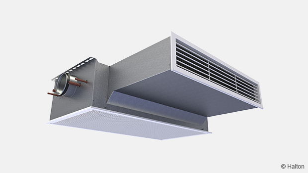
The Halton CHB unit is an active chilled beam for bulkhead and enclosed installation with return and supply air grilles. The Halton CHB has an option of a boost fan integrated into the unit.
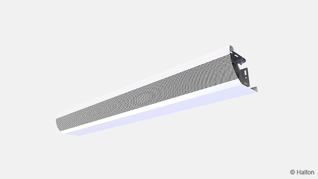
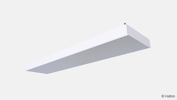
The return- and supply-air grilles shall be openable and removable for maintenance. The return-air grille has a 40-mm telescopic connection and the supply-air grille a 200-mm telescopic connection
The inlet duct connection shall be changeable and able to be located at the right, left, or middle of the supply-air plenum. When there is an integrated fan, there is no option for a connection in the middle.
The heat exchanger of the beam shall be oriented such that the water connections may be on either the right or left side of the beam.
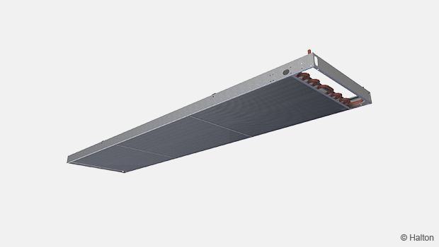
All pipes shall be manufactured from copper, connection pipes with a wall thickness of 0.9–1.0 mm. The fins of the heat exchanger shall be manufactured from aluminium. The heat exchanger shall be factory pressure-tested. The maximum operating pressure of pipework shall be 1.0 MPa.
Each active chilled beam shall be protected by a removable plastic coating and individually packed in a plastic bag. Duct connection and pipe ends shall be sealed during transit.
Each chilled beam shall be identifiable by a serial number printed on a label attached to the active chilled beam.
Dimensions and weight
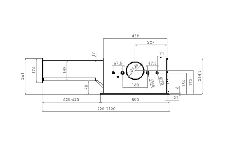
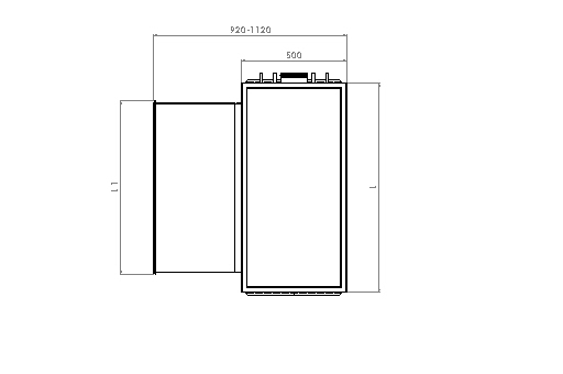
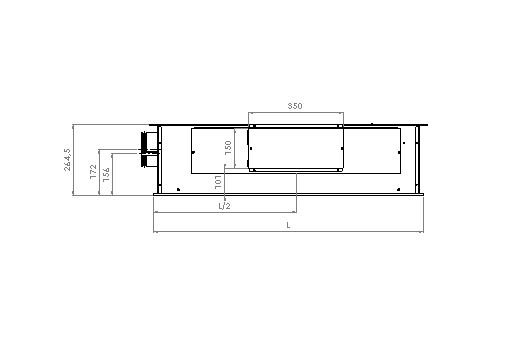
L = 1000/1200/1400
L1 = 826/1026/1226
Inspection and maintenance back of the unit
(BO = Y or BO = R)
Weight
30 kg (excluding water and fan)
Material
| Part | Material | Finishing | Note | ||
| Return-air grille | Pre-painted galvanised steel |
Polyester-painted White (RAL 9003 or RAL 9010, 20% gloss) |
Special colours available. Polyester-epoxy-painted. |
||
| Supply-air grille (WSD) |
Aluminium | Polyester-epoxy-painted White (RAL 9003 or RAL 9010, 20% gloss) |
Special colours available. Polyester-epoxy-painted. |
||
|
Galvanised steel | ||||
| Supply-air plenum | Galvanised steel | ||||
| Brackets | Galvanised steel | ||||
| Coil pipes | Copper | ||||
| Coil fins | Aluminium | ||||
| Fan frame | |||||
| Fan impeller |
Cooling/heating-water pipe connections are Cu15/Cu12 with wall thickness of 0.9–1.0 mm, meeting European standard EN 1057:1996. The maximum operating pressure for chilled/hot-water pipework is 1.0 MPa. The supply-air duct connection diameter is 125 mm.
Accessories
| Accessory | Code | Description | Note |
| Combined cooling and heating coil |
TC = H |
H = coil with additional hot-water circulation. |
Copper water pipe connections are Ø 15 mm (cooling) and Ø 10 mm (heating). |
| Booster fan | BO = see product code |
Boost fan can be installed in factory or delivered later as retrofitted. |
The retrofitting of boost fan is possible only if BO=R selected, when the beam is ordered. |
| Control valve | CV = see product code |
Valves with adjustable Kvs value (Danfoss RA-C, DN 15) or with max. flow limit function (Danfoss AB-QM, DN 10 in heating and Danfoss AB‑QM DN 15 in cooling). |
Delivered loose. |
| Valve actuator | VM = see product code |
Thermal on/off actuators (230 VAC, NC or 24 VAC, NC) for both valve types. Also 230V 0-10V actuator available. |
Delivered loose. Cable length: 1.2 m If controls chosen, 24V actuator not available. |
Function
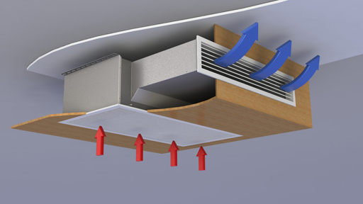
The Halton CHB unit is an active chilled beam for bulkhead installation.
The primary supply air enters the plenum of the active chilled beam, from which it is diffused into the room through nozzles and a supply grille on the front of the chilled beam. The supply-air nozzle jets efficiently induce ambient room air through the return-air grille and the heat exchanger, where it is either cooled or heated. The combined air jet is directed along the ceiling surface.
Three nozzle sizes are available, to enable various supply-air flow rates.
The unit is available in three widths, to meet a wide range of appearance and capacity demands.
The units provide water-side cooling and heating capacity control
The chilled beam can be equipped in the factory with either a standard control valve or a combination control valve.
Controls may include either a standard control valve or a combination control valve. Both are operated with a thermal actuator, and the water-flow rate of the control valve is based on room air temperature. The standard control valve has an adjustable Kvs value. The combination control valve has an adjustable nominal water-flow rate, and there is a pressure difference measurement across the control valve in order to ensure that a great enough pressure differential (min.16 kPa) is available to match the adjusted water-flow rate and the automatic balancing in use.
Installation
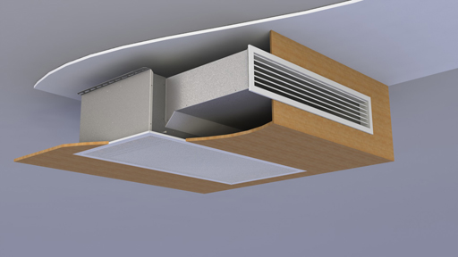
The Halton CHB unit is suitable for bulkhead and suspended-ceiling installation. The chilled beam’s ceiling brackets can be fixed directly to the ceiling surface or suspended by means of threaded drop rods (8 mm). The recommended maximum distance of the supply air grille from the ceiling is 200 mm. The return-air grille has a 40-mm telescopic connection and the supply air grille a 200-mm telescopic connection.
Install the main pipelines of the cooling- and heating-water loops above the level of the chilled beams, to allow venting of the pipework.
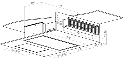
Picture above: If controls or boost selected inspection door needed for maintenance/ installation
Adjustment
Cooling
The recommended cooling-water mass flow rate is 0.02–0.10 kg/s, resulting in a temperature increase of 1–4 °C in the heat exchanger. For avoiding condensation, the recommended inlet-water temperature of the heat exchanger is 14–16 °C.
Heating
The recommended heating-water mass flow rate is 0.01–0.04 kg/s, resulting in a temperature decrease of 5–15 °C in the heat exchanger. The recommended temperature of the inlet water for the heat exchanger is 35–45 °C.
Balancing and control of water-flow rates
Balance the water-flow rates of the chilled beam with the standard control valve by selecting the desired Kvs value in the valve body. When using an automatically balancing combination valve, set the desired water-flow rate in the valve body, and verify the pressure difference (min.: 16 kPa) across the valve. Regulating the water mass flow rate controls the cooling and heating capacity of the chilled beam.
Adjustment of the supply-air flow rate
Each chilled beam is equipped with a measurement tap for static pressure measurement, which enables fast and accurate measurement of the rate of supply-air flow through the beam. The air-flow rate is calculated by means of the formula below.

Where k value is determined according table below:
| Nozzle | Width | k [l/s] | k [m3/h] |
| A | 1000 | 2,14 | 7,71 |
| A | 1200 | 2,83 | 10,20 |
| A | 1400 | 3,59 | 12,91 |
| B | 1000 | 2,93 | 10,55 |
| B | 1200 | 3,90 | 14,06 |
| B | 1400 | 4,97 | 17,91 |
| C | 1000 | 4,00 | 14,40 |
| C | 1200 | 5,39 | 19,41 |
| C | 1400 | 6,94 | 24,99 |
Servicing
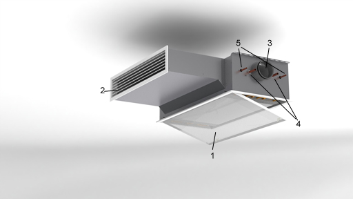
Code Description
1. Return air grille
2. Supply air grille
3. Supply air connection
4. Chilled water pipe connections
5. Heating water pipe connections
Open the return-air grille of the chilled beam. Clean the finned coils of the heat exchanger with a vacuum cleaner, taking care not to damage the finned coils. Clean the return- and supply-air grilles with a damp cloth.
Check at regular intervals that the actuators and water-flow control valves are working.
Specification
The Halton CHB unit is an active chilled beam for bulkhead and enclosed installation with return and supply air grilles. The Halton CHB has an option of a boost fan integrated into the unit.
The return- and supply-air grilles shall be openable and removable for maintenance. The return-air grille has a 40-mm telescopic connection and the supply-air grille a 200-mm telescopic connection
The inlet duct connection shall be changeable and able to be located at the right, left, or middle of the supply-air plenum. When there is an integrated fan, there is no option for a connection in the middle.
The heat exchanger of the beam shall be oriented such that the water connections may be on either the right or left side of the beam.
All pipes shall be manufactured from copper, connection pipes with a wall thickness of 0.9–1.0 mm. The fins of the heat exchanger shall be manufactured from aluminium. The heat exchanger shall be factory pressure-tested. The maximum operating pressure of pipework shall be 1.0 MPa.
Each active chilled beam shall be protected by a removable plastic coating and individually packed in a plastic bag. Duct connection and pipe ends shall be sealed during transit.
Each chilled beam shall be identifiable by a serial number printed on a label attached to the active chilled beam.
Order Code
CHB/S-W-E-K; CO-TC-BO-CV-VM-ZT
S = Nozzle type
A Nozzle 5
B Nozzle 6
C Nozzle 7
W = Total width of the unit
1000 1000 mm
1200 1200 mm
1400 1400 mm
E = Location of supply-air connection
R Right
L Left
M Middle (not possible with BO=Y or BO=R)
K = Location of pipe connections
R Right
L Left
Other options and accessories
CO = Colour of grilles
SW Signal white (RAL 9003)
W Pure white (RAL 9010)
X Special colour (RALxxxx)
TC = Cooling/heating functions (coil type)
C Cooling
H Cooling and heating
BO = Booster fan
N No
Y Yes
R Retrofit possibility
CV = Control valves
N Not assigned
A2 Adjustable Kvs (Danfoss RA-C, DN 15), loose
A4 Max. flow limit (Danfoss AB-QM),
DN 10 (heating) and DN 15 (cooling),
deliverd loose
VM = Valve actuator
N Not assigned
A1 24V On-Off
A2 230V On-Off
A3 24V 0-10V Modulating
ZT = Tailored product
N No
Y Yes (ETO)
Code example
CHB /A-1000-L-R, CO=SW, TC=H, BO=Y, CV=A2, VM=A2, ZT=N
