Product / CHB
Halton CHB – Chilled beam
Boost function gives the possibility for fast control of room temperature.
- Combined cooling, heating, and supply-air unit for bulkhead installation
- Different sizes, to meet various cooling and air-flow demands
Overview
- Combined cooling, heating, and supply-air unit for bulkhead installation
- Different sizes, to meet various cooling and air-flow demands
- Fulfilling high requirements for thermal comfort and silent conditions spaces
- Boost allows the fast response to the cooling and heating capacity of the unit by 50-80% depending on the performance point
- Enhanced life-cycle performance:
- Energy-efficient solution with low air and water flow in both cooling and heating modes
- Suitability for systems using free energy sources and heat pumps
- Low-cost maintenance due to a simple and hygienic principle of operation.
- Operates as a non-condensing dry system with minimal use of mechanical parts: no mechanical filters, condensation tray, or drainage piping
- Suitable for both renovation projects and new construction
Product models and accessories
- Model with combined cooling and heating coil
- Models with three different width
- Model for eventual boost-fan retrofitting
- Integrated control valves and actuators – delivered loose
Halton chilled beams are certified by Eurovent Certita.

Dimensions and weight


L = 1000/1200/1400
L1 = 826/1026/1226
Inspection and maintenance back of the unit
(BO = Y or BO = R)

Weight
30 kg (excluding water and fan)
Material
| Part | Material | Finishing | Note |
| Return-air grille | Pre-painted galvanised steel |
Polyester-painted White (RAL 9003, 20% gloss) |
Special colours available. Polyester-epoxy-painted. |
| Supply-air grille (WSD) |
Aluminium | Polyester-epoxy-painted White (RAL 9003, 20% gloss) |
Special colours available. Polyester-epoxy-painted. |
| Casing | Galvanised steel | – | – |
| Supply-air plenum | Galvanised steel | – | – |
| Brackets | Galvanised steel | – | – |
| Coil pipes | Copper | – | – |
| Coil fins | Aluminium | – | – |
| Fan frame | – | – | – |
| Fan impeller | – | – | – |
Cooling/heating-water pipe connections are Cu15/Cu12 with wall thickness of 0.9–1.0 mm, meeting European standard EN 1057:1996. The maximum operating pressure for chilled/hot-water pipework is 1.0 MPa. The supply-air duct connection diameter is 125 mm.
Accessories
| Accessory | Code | Description | Note |
| Combined cooling and heating coil |
TC = H |
H = coil with additional hot-water circulation. |
Copper water pipe connections are Ø 15 mm (cooling) and Ø 10 mm (heating). |
| Booster fan | BO = see product code |
Boost fan can be installed in factory or delivered later as retrofitted. |
The retrofitting of boost fan is possible only if BO=R selected, when the beam is ordered. |
| Control valve | CV = see product code |
Valves with adjustable Kvs value (Danfoss RA-C, DN 15) or with max. flow limit function (Danfoss AB-QM, DN 10 in heating and Danfoss AB‑QM DN 15 in cooling). |
Delivered loose. |
| Valve actuator | VM = see product code |
Thermal on/off actuators (230 VAC, NC or 24 VAC, NC) for both valve types. Also 230V 0-10V actuator available. |
Delivered loose. Cable length: 1.2 m If controls chosen, 24V actuator not available. |
Function
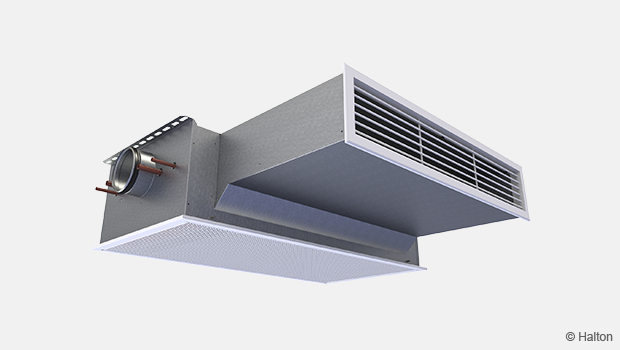
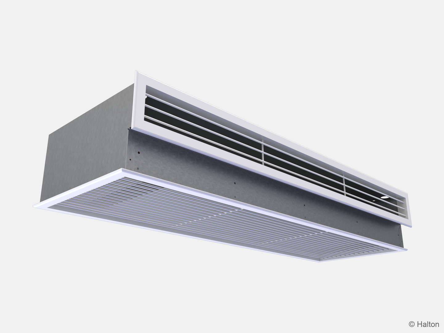
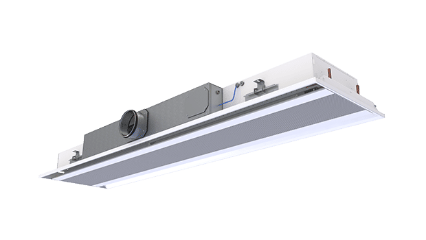
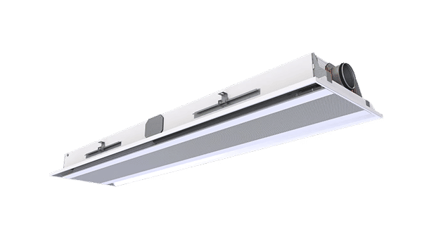
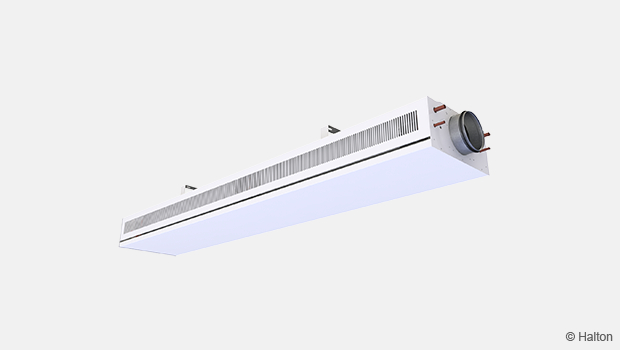
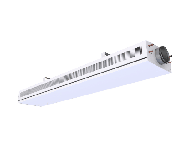
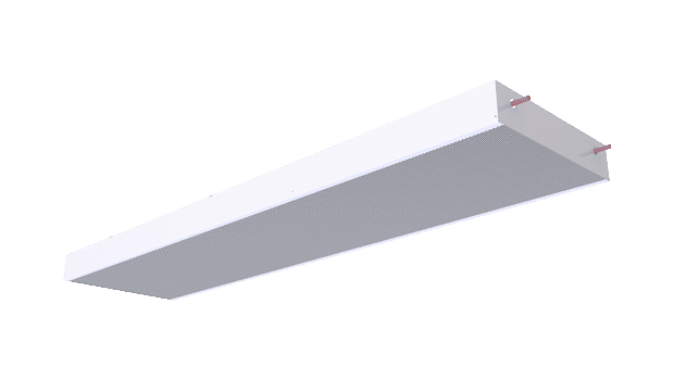
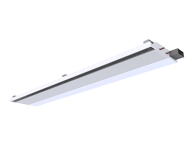
The Halton CHB unit is an active chilled beam for bulkhead installation.
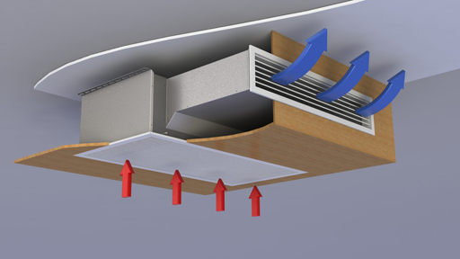
The primary supply air enters the plenum of the active chilled beam, from which it is diffused into the room through nozzles and a supply grille on the front of the chilled beam. The supply-air nozzle jets efficiently induce ambient room air through the return-air grille and the heat exchanger, where it is either cooled or heated. The combined air jet is directed along the ceiling surface.
Three nozzle sizes are available, to enable various supply-air flow rates.
The unit is available in three widths, to meet a wide range of appearance and capacity demands.
The units provide water-side cooling and heating capacity control
The chilled beam can be equipped in the factory with either a standard control valve or a combination control valve.
Controls may include either a standard control valve or a combination control valve. Both are operated with a thermal actuator, and the water-flow rate of the control valve is based on room air temperature. The standard control valve has an adjustable Kvs value. The combination control valve has an adjustable nominal water-flow rate, and there is a pressure difference measurement across the control valve in order to ensure that a great enough pressure differential (min.16 kPa) is available to match the adjusted water-flow rate and the automatic balancing in use.
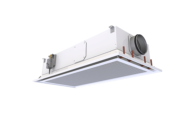
Installation
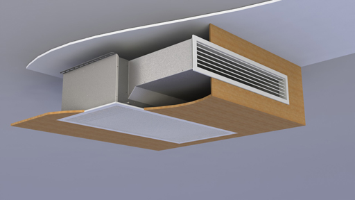
The Halton CHB unit is suitable for bulkhead and suspended-ceiling installation. The chilled beam’s ceiling brackets can be fixed directly to the ceiling surface or suspended by means of threaded drop rods (8 mm). The recommended maximum distance of the supply air grille from the ceiling is 200 mm. The return-air grille has a 40-mm telescopic connection and the supply air grille a 200-mm telescopic connection.
Install the main pipelines of the cooling- and heating-water loops above the level of the chilled beams, to allow venting of the pipework.

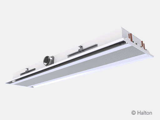
Picture above: If controls or boost selected inspection door needed for maintenance/ installation
Adjustment
Cooling
The recommended cooling-water mass flow rate is 0.02–0.10 kg/s, resulting in a temperature increase of 1–4 °C in the heat exchanger. For avoiding condensation, the recommended inlet-water temperature of the heat exchanger is 14–16 °C.
Heating
The recommended heating-water mass flow rate is 0.01–0.04 kg/s, resulting in a temperature decrease of 5–15 °C in the heat exchanger. The recommended temperature of the inlet water for the heat exchanger is 35–45 °C.
Balancing and control of water-flow rates
Balance the water-flow rates of the chilled beam with the standard control valve by selecting the desired Kvs value in the valve body. When using an automatically balancing combination valve, set the desired water-flow rate in the valve body, and verify the pressure difference (min.: 16 kPa) across the valve. Regulating the water mass flow rate controls the cooling and heating capacity of the chilled beam.
Adjustment of the supply-air flow rate
Each chilled beam is equipped with a measurement tap for static pressure measurement, which enables fast and accurate measurement of the rate of supply-air flow through the beam. The air-flow rate is calculated by means of the formula below.
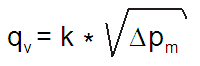
Where k value is determined according table below:
| Nozzle | Width | k [l/s] | k [m3/h] |
| A | 1000 | 2,14 | 7,71 |
| A | 1200 | 2,83 | 10,20 |
| A | 1400 | 3,59 | 12,91 |
| B | 1000 | 2,93 | 10,55 |
| B | 1200 | 3,90 | 14,06 |
| B | 1400 | 4,97 | 17,91 |
| C | 1000 | 4,00 | 14,40 |
| C | 1200 | 5,39 | 19,41 |
| C | 1400 | 6,94 | 24,99 |
Servicing
Code Description
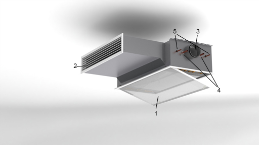
1. Return air grille
2. Supply air grille
3. Supply air connection
4. Chilled water pipe connections
5. Heating water pipe connections
Open the return-air grille of the chilled beam. Clean the finned coils of the heat exchanger with a vacuum cleaner, taking care not to damage the finned coils. Clean the return- and supply-air grilles with a damp cloth.
Check at regular intervals that the actuators and water-flow control valves are working.
Specification
The Halton CHB unit is an active chilled beam for bulkhead and enclosed installation with return and supply air grilles. The Halton CHB has an option of a boost fan integrated into the unit.
The return- and supply-air grilles shall be openable and removable for maintenance. The return-air grille has a 40-mm telescopic connection and the supply-air grille a 200-mm telescopic connection
The inlet duct connection shall be changeable and able to be located at the right, left, or middle of the supply-air plenum. When there is an integrated fan, there is no option for a connection in the middle.
The heat exchanger of the beam shall be oriented such that the water connections may be on either the right or left side of the beam.
All pipes shall be manufactured from copper, connection pipes with a wall thickness of 0.9–1.0 mm. The fins of the heat exchanger shall be manufactured from aluminium. The heat exchanger shall be factory pressure-tested. The maximum operating pressure of pipework shall be 1.0 MPa.
Each active chilled beam shall be protected by a removable plastic coating and individually packed in a plastic bag. Duct connection and pipe ends shall be sealed during transit.
Each chilled beam shall be identifiable by a serial number printed on a label attached to the active chilled beam.
Order Code
CHB/S-W-E-K; CO-TC-BO-CV-VM-ZT
S = Nozzle type
A Nozzle 5
B Nozzle 6
C Nozzle 7
W = Total width of the unit
1000 1000 mm
1200 1200 mm
1400 1400 mm
E = Location of supply-air connection
R Right
L Left
M Middle (not possible with BO=Y or BO=R)
K = Location of pipe connections
R Right
L Left
Other options and accessories
CO = Colour of grilles
SW Signal white (RAL9003)
X Special colour (RALxxxx)
TC = Cooling/heating functions (coil type)
C Cooling
H Cooling and heating
BO = Booster fan
N No
Y Yes
R Retrofit possibility
CV = Control valves
N Not assigned
A2 Adjustable Kvs (Danfoss RA-C, DN 15), loose
A4 Max. flow limit (Danfoss AB-QM),
DN 10 (heating) and DN 15 (cooling), deliverd loose
VM = Valve actuator
N Not assigned
A1 24V On-Off
A2 230V On-Off
A3 24V 0-10V Modulating
ZT = Tailored product
N No
Y Yes (ETO)
Code example
CHB /A-1000-L-R, CO=SW, TC=H, BO=Y, CV=A2, VM=A2, ZT=N
Pictures
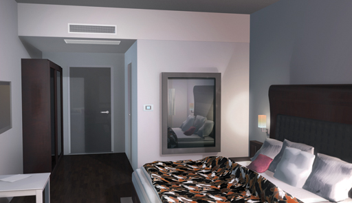
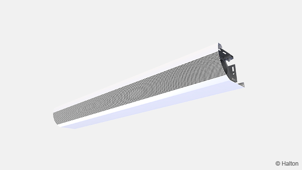
Fig.1. 3D-image with room controller (CHB).
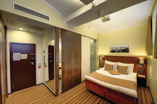
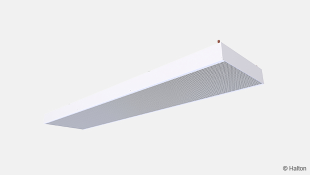
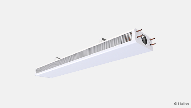
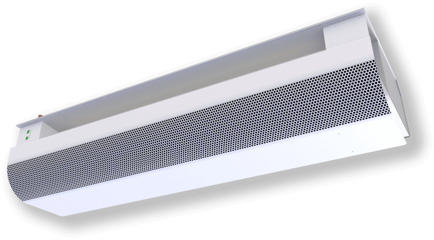
Fig.2. Hotel Best Western Premier Katajanokka, Helsinki, Finland
In picture CHH, witch has similar outlook as CHB
Downloads
"*" indicates required fields
Halton CaBeam – Chilled beam for exposed wall installation
product
Halton CaBeam – Chilled beam for integrated installation
product
Halton CaBeam – Chilled beam for recessed installation
product
Halton CBH – Chilled beam
product
Halton CHB – Chilled beam
product
Halton CPA – Passive chilled beam
product
Halton CSW – Swirl comfort unit
product
Halton Rex R6W – Variable air volume chilled beam (VAV)
product
Halton Rex RE6 – Chilled beam
product
Halton Rex REE – Chilled beam
product
Halton Rex REO – Chilled beam (VAV)
product
Halton Rex REW – VAV chilled beam
product
Halton Rex RXP – Chilled beam (CAV/VAV)
product

Halton Vita VPR – Hygienic chilled beam
product
NEW! Halton CaBeam REC – For Passenger and Crew Cabins
product
NEW! Halton Rex REP – Passive chilled beam
product
NEW! Halton Rex RSI – Slim induction unit
product