Product / RXP
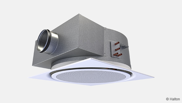
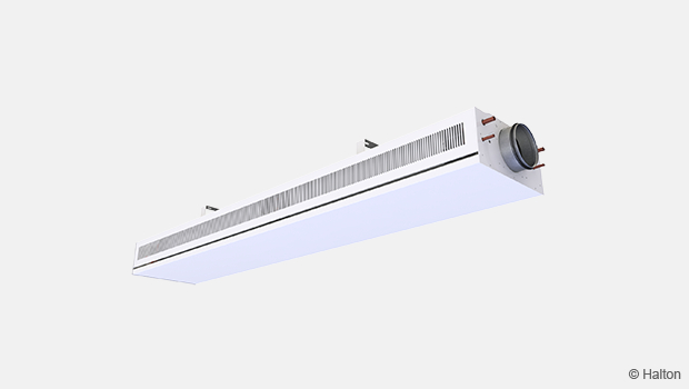
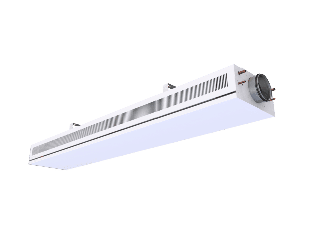
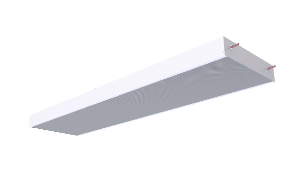
Halton Rex RXP – Chilled beam (CAV/VAV)
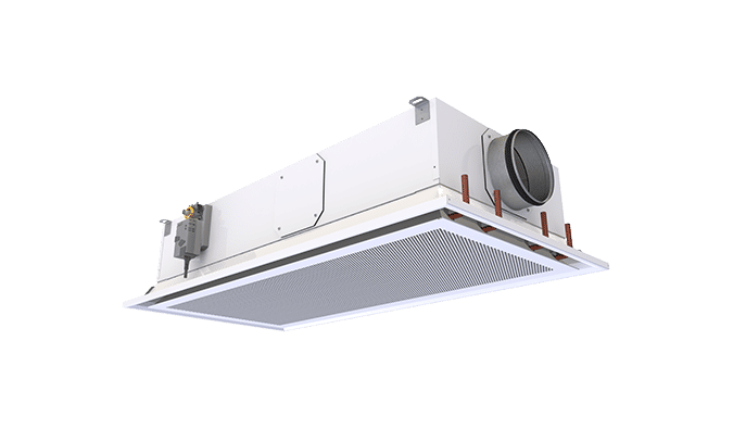
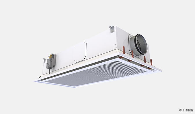
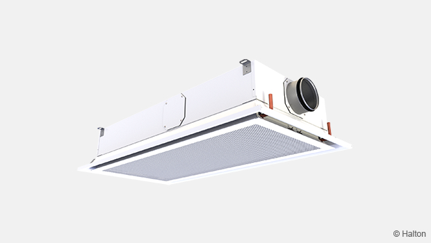
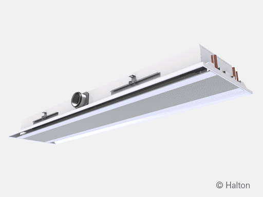
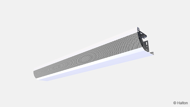
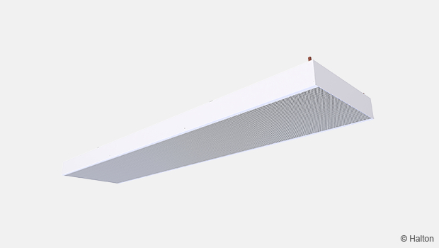
Compact fully flexible CAV/VAV chilled beam with 4-way air distribution for suspended ceilings.
Ensures silent and pleasant room conditions even with higher cooling capacities.
- Active chilled beam with 4-way air distribution.
- Three product models with adjustable airflow using manual CAV or motorised VAV
- Standard model with boost airflow control and pressure dependent operation
- Flexible model with 0-100% airflow control and pressure dependent operation
- Autonomic model with 0-100% airflow control and pressure independent operation

Overview
Compact fully flexible CAV/VAV chilled beam with 4-way air distribution for suspended ceilings. Ensures silent and pleasant room conditions even with higher cooling capacities.
Application area
- Cooling and ventilation in offices, hospital rooms, schools, and public spaces.
- Can be used in Halton’s demand-based ventilation systems.
Key features
- Active chilled beam with 4-way air distribution.
- Three product models with adjustable airflow using manual CAV or motorised VAV
- Standard model with boost airflow control and pressure dependent operation
- Flexible model with 0-100% airflow control and pressure dependent operation
- Autonomic model with 0-100% airflow control and pressure independent operation
- Throw pattern expanded to corners, which ensures pleasant room conditions even with high cooling capacities.
- Model with Halton Workplace WRA, room automation system package
Halton chilled beams are certified by Eurovent Certita.

Operating principle
The primary supply air enters the plenum of the Halton Rex RXP chilled beam, from which it is diffused into the room through the nozzles and supply slots. The air jets from the nozzles induce ambient room air efficiently through the heat exchanger, where the air is cooled by means of the cool water circulating in the heat exchanger. The supply slots direct the air jets horizontally along the ceiling surface, which prevents the feeling of draught.
The blue arrows in Fig.1. show the supply air coming through the supply slots. The red arrows show the ambient room air going through the front panel and the heat exchanger.
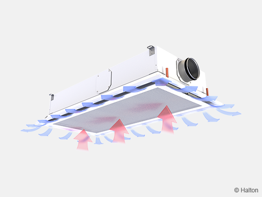
Fig.1. Operating principle of the Halton Rex RXP chilled beam
Halton Air Quality (HAQ) control in Halton Rex RXP, standard model
Halton Air Quality (HAQ) boost airflow control is used for adjusting or controlling the rate of the additional supply airflow in a room space. In normal conditions, fresh supply air is provided through the nozzles. Whenever additional air is needed (boost/VAV function), the HAQ control opens and provides more air. VAV stands for Variable Air Volume.
The HAQ control can also be used as a Constant Air Volume (CAV) damper, that is, it can be used for adjusting the k-factor to achieve the correct airflow with a certain pressure level. This removes the need for changing or plugging the nozzles of the Halton Rex RXP chilled beam.
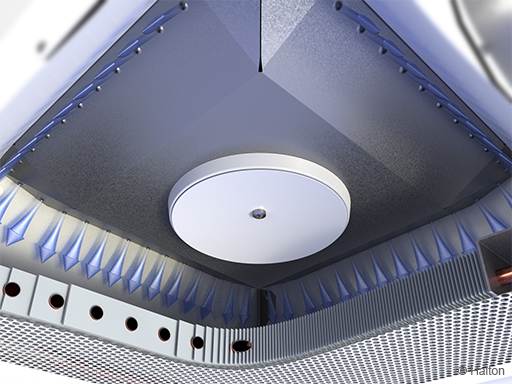
Fig.2. VAV function: Supply air from nozzles (normal mode)
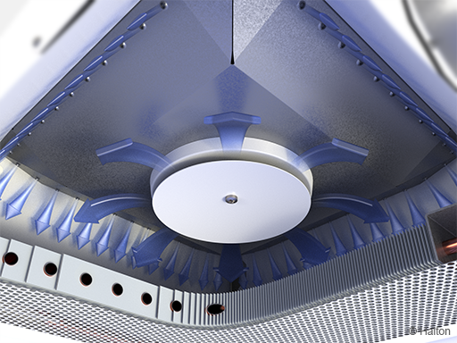
Fig.3. VAV function with HAQ control: Supply air from nozzles and HAQ control (boost mode).
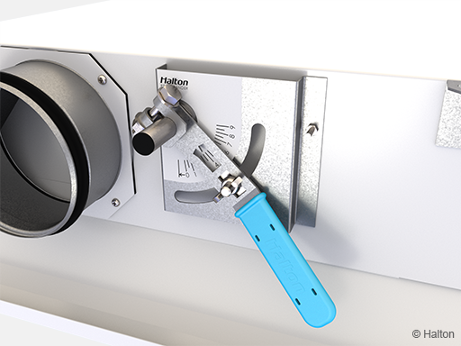
Fig.4. Adjustment of the manual actuator of HAQ control in Halton Rex RXP, Standard model
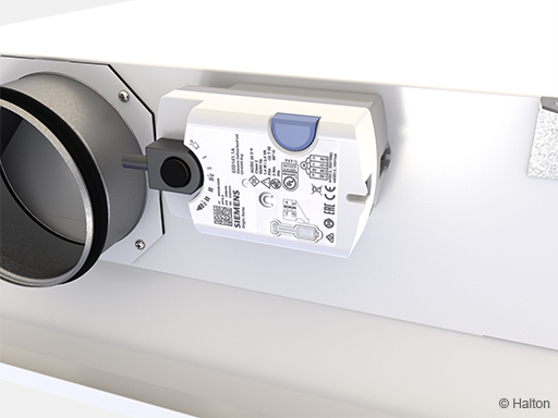
Fig.5. Electric actuator of HAQ control in Halton Rex RXP, Standard model
Halton Operation Mode Damper (OMD) in Halton Rex RXP, Flexible model
Halton Operation Mode Damper (OMD) fully flexible airflow control is used for manual supply airflow adjustment or for motorised Variable Air Volume (VAV) control of the supply airflow rate. The OMD control flexibly combines nozzle and HAQ airflow control providing full airflow flexibility with one nozzle configuration.
The OMD control can be used as a Constant Air Volume (CAV) damper, that is, it can be used for adjusting the k-factor to achieve the correct airflow with a certain pressure level. This removes the need for changing or plugging the nozzles of the Halton Rex RXP chilled beam.
When the OMD control is equipped with a motorised actuator, fully flexible VAV control is achieved. It allows different VAV modes with for instance minimum, normal and boost airflow settings.
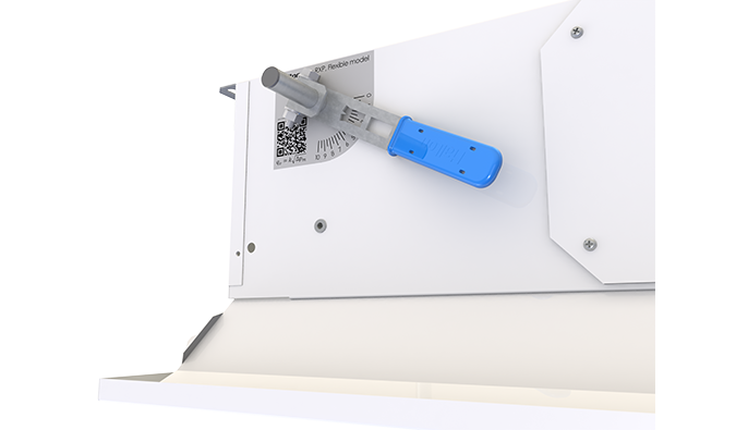
Fig. 6. Adjustment of the manual actuator of OMD control in Halton Rex RXP, Flexible model
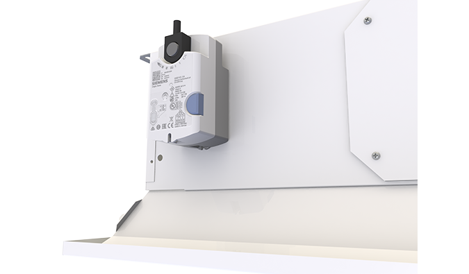
Fig. 7. Electric actuator of OMD control in Halton Rex RXP, Flexible model
Halton Operation Mode Damper (OMD) in Halton Rex RXP, Autonomic model
Halton Operation Mode Damper (OMD) fully flexible airflow control is used for manual supply airflow adjustment or for motorised Variable Air Volume (VAV) control of the supply airflow rate. The OMD control flexibly combines nozzle and HAQ airflow control providing full airflow flexibility with one nozzle configuration.
In Halton Rex RXP, Autonomic model, when the OMD control is equipped with a motorised actuator integrated with pressure measurement, fully flexible VAV control with pressure independent operation is achieved. It allows different VAV modes with for instance minimum, normal and boost airflow settings.
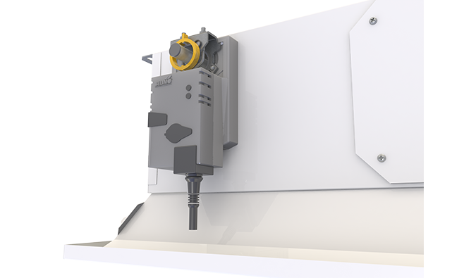
Fig. 8. Electric actuator integrated with pressure measurement of OMD control in Halton Rex RXP, Autonmic model
Velocity control in the occupied zone
Halton Rex RXP, Flexible and Autonomic models can be equipped with Halton Velocity Control (HVC). It is used for adjusting room air velocity conditions either when room layout is changed (e.g., in cases where the partition wall is located near the chilled beam) or when local, individual velocity conditions need to be altered. HVC adjustment has an impact on the induced room air flow through the heat exchanger, and therefore it either increases or decreases both the velocities in the occupied zone and the cooling/heating capacity of the chilled beam.
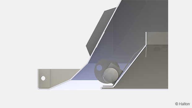
Fig. 9. HVC in position Normal
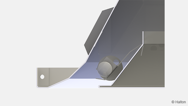
Fig. 10. HVC in position Throttle
There are HVC controls in all four sides of Halton Rex RXP chilled beam. The HVC is divided into two parts in the long sides of RXP-1200 chilled beam. This enables the adjustment of conditions in different parts of the occupied zone.
Key technical data
| Feature | Description |
| Airflow rate | Max. airflow rate 57 l/s or 205 m³/h (RXP/S-E-1200); 65 l/s or 234 m³/h (RXP/F-F-1200 and RXP/A-F-1200) < 35 dB |
| Dimensions | 600×600 mm or 1200×600 mm |
| Water pressure drop | Max. 18,6 kPa (RXP-1200, waterflow 0,1 kg/s) |
| Cooling capacity | Up to 1 700 W (RXP/S-E-1200, 100 Pa, 57 l/s, water inlet 14 °C, water mass flow 0,1 kg/s, supply air 16 °C) |
| Weight | 10–22 kg (RXP/S) and 17-31 kg (RXP/F and RXP/A) |
| Typical total pressure drop | 60–80 Pa |
| Typical water temperature |
|

Features and options
| Category | Feature (order code) |
Option (order code) |
Description |
| Product model |
Model M |
S | Standard product model with nozzle and HAQ airflow control options. |
| Size and orientation | Product length L |
600, 1200 | Two different lengths. Nominal width is always 600 mm. |
| Duct connection E |
S2, R2, L2 | Ø 125 mm. Factory-positioned straight, right, or left. Position can be changed on site. See Fig.9. below. | |
| S3, R3, L3 | Ø 160 mm. Factory-positioned straight, right, or left. Position can be changed on site. See Fig.9. below. Note: Only available if L=1200 and nozzle type=E. |
||
| Cooling/ Heating |
Coil type TC |
C | Cooling coil. Connection pipes 2 x Ø 12 mm. |
| H | Cooling and heating coil. Connection pipes: 4 x Ø 12 mm. | ||
| Airflow | Nozzle type S |
C, D, E | 3 options for different airflow or k-factor needs. Nozzle C is the smallest and nozzle E is the largest. |
| Control type CN |
NA | No HAQ. K-factor is determined by nominal size and nozzle selection (CAV) | |
| MA | Manually adjustable CAV control of additional airflow. Standard air from nozzles, additional air from HAQ. | ||
| M1 | Motorised VAV control of additional airflow Standard air from nozzles, additional air from HAQ. | ||
| Room air velocity level | Velocity control (HVC) VC |
N | No HVC function. |
Table 1. Halton Rex RXP, Standard model (RXP/S)
| Category | Feature (order code) |
Option (order code) |
Description |
| Product model |
Model M |
F | Flexible product model with fully flexible OMD airflow control options. |
| A | Autonomic product model with fully flexible OMD airflow control options integrated with pressure measurement. | ||
| Size and orientation | Product length L |
600, 1200 | Two different lengths. Nominal width is always 600 mm. |
| Duct connection E |
S3, R3, L3 | Ø 160 mm. Factory-positioned straight, right, or left. Position can be changed on site. See Fig.9. below. Note: Only available if L=1200 and nozzle type=E. |
|
| Connection type (air and water) CT |
S | Air and water connections at the same end. | |
| O | Air and water connections at the opposite ends. | ||
| Cooling/ Heating |
Coil type TC |
C | Cooling coil. Connection pipes 2 x Ø 12 mm. |
| H | Cooling and heating coil. Connection pipes: 4 x Ø 12 mm. | ||
| Airflow | Nozzle type S |
F | No nozzle options, nozzle type is always F providing extensive airflow range with OMD airflow adjustment/control. |
| Control type CN |
MA | Manually adjustable airflow (CAV) (available when M=F) | |
| M1 | Motorised airflow control 0… 10 VDC (VAV). | ||
| M2 | Motorised airflow control Modbus RTU/BACnet MSTP (VAV) | ||
| Room air velocity level | Velocity control (HVC) VC |
N | No HVC function. |
| Y | Yes, HVC function included |
Table 2. Halton Rex RXP, Flexible model (RXP/F) and Autonomic model (RXP/A)
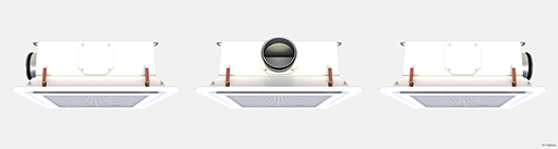
Fig.9. Duct connection: Spigot positions left, straight, right
For more detailed information on the order code, see section Order code.
System package
Halton Workplace WRA room automation system package for Halton Rex RXP chilled beam, Standard model (RXP/S)
Halton Workplace WRA is part of the Halton Workplace solution offering.
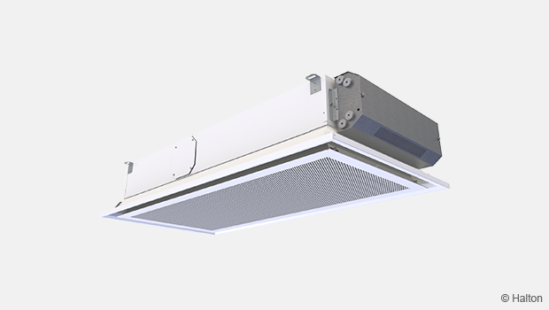
Fig. 10: Halton Workplace WRA room automation controller integrated to Halton Rex RXP chilled beam
Halton Workplace WRA is a controller especially designed for controlling the automation system of office spaces and meeting rooms. It is used for controlling the ventilation airflow, room temperature, and indoor air quality.
The Halton Workplace WRA room automation package consists of a controller unit and optional components depending on customer needs: a wall panel and sensors for temperature, CO2, occupancy, pressure, and condensation.
There are options available for the controller unit and wall panel, depending on the number of controls and sensors required. The Halton Workplace WRA room automation controller is always combined with other Halton products for adaptable and high-level indoor climate.
Application area
- Controlling the ventilation airflow, room temperature, and indoor air quality in office spaces and meeting rooms
- The Halton Workplace WRA room automation controller is an important part of the Halton Workplace system, controlling room units and airflow control dampers
- Overall Halton Workplace System includes:
- Room air conditioning applications with Halton Workplace WRA room automation controller:
- Active chilled beams
- Exhaust units
- VAV dampers
- Active VAV diffusers
- Halton Max MDC zone control dampers
- Room air conditioning applications with Halton Workplace WRA room automation controller:
Key features
- Factory-tested controller and wiring, easy to install
- Pre-installed project-specific parameters, quick to commission
- Several operating modes based on occupancy, thermal comfort, and indoor air quality
- Enables fully flexible layout solutions for changing needs in office environments
- Highly energy-efficient and reliable system operation
Operating principle
The Halton Workplace WRA room automation controller operates with Variable Air Volume (VAV) dampers and active chilled beams of the Halton Workplace system. These are used for adjusting the ventilation airflow, room temperature, and indoor air quality in office spaces.
Each room unit in an office space can have its own dedicated Halton Workplace WRA room automation controller, or a single controller can control multiple room units. The Halton Workplace WRA room automation controller can automatically adjust the system according to the indoor environment level preferred by users. Each room unit having its own dedicated controller brings maximum flexibility.
Room automation: Halton Rex RXP active chilled beams with HAQ control and PTS damper, controlled with Halton Workplace WRA room automation controllers
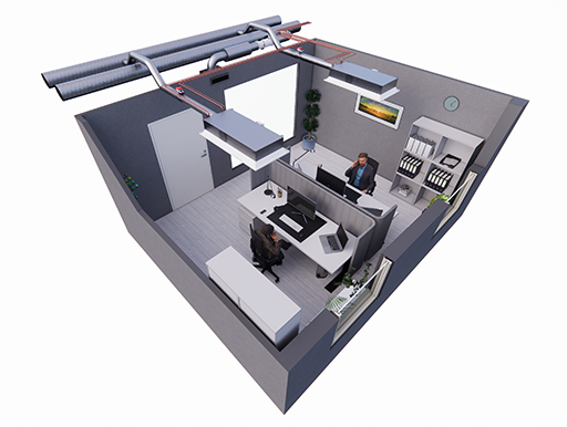
Fig. 11. Halton Rex RXP active chilled beams with HAQ control and PTS damper, controlled with Halton Workplace WRA room automation controllers in a double office room
Room automation description
In this configuration, two Halton Workplace WRA room automation controllers (type DXR2.E18-102A) control two Halton Rex RXP active chilled beams. Each chilled beam has heating and cooling valves, motorised Halton Air Quality (HAQ) control, as well as integrated CO2, pressure, and condensation sensors. A Halton PTS single-blade damper is used for controlling the minimum operating mode. The system also includes an exhaust VAV damper, window switch control, external occupancy sensor and a wall panel (type QMX3.P37) with a temperature sensor and display. One Halton Workplace WRA room automation controller can individually control up to four terminal units, and there can be several Halton Workplace WRA room automation controllers in the room.
Design criteria for room automation
- Chilled beam has heating and cooling valves
- Chilled beam has motorised HAQ control
- Chilled beam has integrated CO2, pressure, and condensation sensors
- External occupancy sensor
- Wall panel with temperature sensor and display
- Window switch control
- Optional PTS damper for controlling minimum airflow
- Exhaust airflow control
Schematic drawing

Fig. 12: Schematic drawing: Halton Rex RXP chilled beam (4-pipe) controlled with Halton Workplace WRA room automation controller
Equipment list
| Code | Equipment |
| RC | Controller unit |
| FG | Airflow damper actuator |
| FC | Airflow measurement |
| H | Water valve actuator |
| CS | Condensation sensor |
| OS | Occupancy sensor |
| PE | Pressure sensor |
| CO2 | CO2 sensor |
| WP | Wall panel |
| TE | Temperature sensor |
| TI | Temperature display |
| WS | Window switch control |
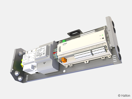
Fig. 13: Factory-installed Halton Workplace WRA room automation controller, type DXR2.E18-102A
Wiring diagram
For the wiring diagram of similar configuration, see the product page of Halton Workplace WRA room automation controller, section Installation information.
Components and order code examples for the system
- 2 x Active chilled beam: Halton Rex RXP
RXP/C-1200-S2, TC=H, AQ=MO, CO=SW, ZT=N - 1 x Exhaust unit: Halton AGC Exhaust grille + Halton PRL Plenum for grilles
AGC/N-400-100 FS=CL, ME=A, FI=PN, CO=W, ZT=N+PRL/F-400-100-160 - 1 x VAV damper: Halton Max Ultra Circular (MUC) or Halton Max One Circular (MOC)
MUC/G-160, MA=CS - 2 x standby, shut-off damper: Halton PTS
PTS/A-125, MA=CS, MO=B4, ZT=N - 2 x standby, shut-off damper: Halton PTS
PTS/A-125, MA=CS, MO=B4, ZT=N - Automation package: 2 x Halton Workplace WRA room automation controller unit with related components
WRA/RXP-E81-H3-EX4, WP=37, LC=NA, SE=CI, SW=NC, ST=IA, SL=OI, PM=P1, TC=H, CV=SP5, RV=NA, ZT=N
Note: For more information, see the product pages of the Halton Workplace WRA room automation controller
Cooling and heating water valve selection in Halton Workplace WRA room automation system package
Water valve selection is done in Halton Workplace WRA room automation system package. Water valve sizing depends on the number of secondary and primary chilled beam units that are controlled with single controller. One water valve is used to control the whole chilled beam group cooling or heating operated by one room controller. Water valve is sized for whole group when there are multiple chilled beams controlled with single controller. There can be one primary chilled beam with room controller and up to three secondary chilled beams. Water valve sizing for 1-4 chilled beams is shown below.
| Number of chilled beams (pcs.) | Water valve type | Size for cooling (DN) | Size for heating (DN) | Installation |
| 1 | ABQM | DN15 | DN15 | Integrated to chilled beam |
| 2 | ABQM | DN20 | DN15 | Loose |
| 3 | ABQM | DN20 | DN15 | Loose |
| 4 | ABQM | DN25 | DN15 | Loose |
| Number of chilled beams (pcs.) | Water valve type | Size for cooling (DN) | Size for heating (DN) | Installation |
| 1 | VPP46.. | DN15 | DN15 | Loose |
| 2 | VPP46.. | DN20 | DN15 | Loose |
| 3 | VPP46.. | DN20 | DN15 | Loose |
| 4 | VPP46.. | DN25 | DN15 | Loose |
Quick selection
Airflow
Halton Rex RXP, standard model
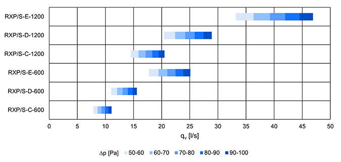
Fig.14. Airflow ranges in l/s for Halton Rex RXP, standard model without HAQ/with HAQ closed with different static chamber pressure levels

Fig.15. Airflow ranges in m3/h for Halton Rex RXP, standard model without HAQ/with HAQ closed with different static chamber pressure levels
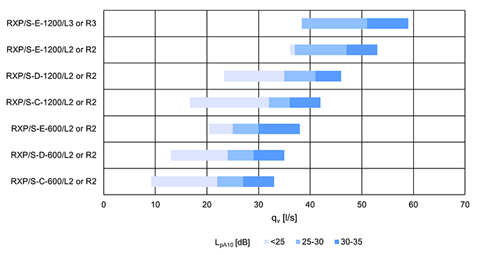
Fig. 16. Airflow ranges in l/s for Halton Rex RXP, standard model with HAQ @70 Pa total pressure
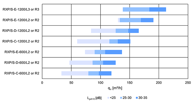
Fig. 17. Airflow ranges in m3/h for Halton Rex RXP standard model with HAQ @70 Pa total pressure
Halton Rex RXP, Flexible and Autonomic models
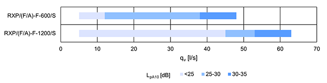
Fig. 18. Airflow ranges in l/s for Halton Rex RXP, Flexible and Autonomic models @70 Pa total pressure
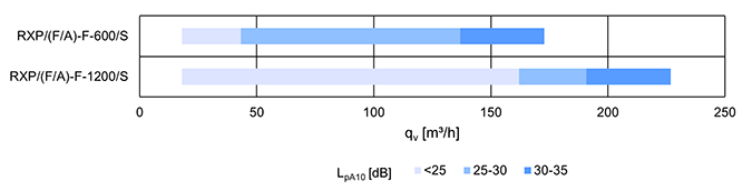
Fig. 19. Airflow ranges in m3/h for Halton Rex RXP, Flexible and Autonomic models @70 Pa total pressure
Cooling capacity
Halton Rex RXP, Standard model
| Product model with HAQ/OMD | Inlet/outlet water temp. [°C] | Room temp. [°C] | Total pressure [Pa] | Water massflow [kg/s] | Airflow 30DbA [l/s) | Capacity [W] | ||
| Water | Air (18°C) | Total | ||||||
| RXP/S-C-600 | 15/17 | 25 | 75 | 0.03 | 27 | 249 | 229 | 478 |
| RXP/S-D-600 | 0.035 | 29 | 290 | 246 | 537 | |||
| RXP/S-E-600 | 0.047 | 30 | 390 | 255 | 645 | |||
| RXP/S-C-1200 | 15/18 | 0.038 | 36 | 483 | 306 | 789 | ||
| RXP/S-D-1200 | 0.047 | 42 | 596 | 357 | 953 | |||
| RXP/S-E-1200 | 0.055 | 48 | 687 | 408 | 1095 | |||
Halton Rex RXP, Flexible and Autonomic models
| Product model with HAQ/OMD | Inlet/outlet water temp. [°C] | Room temp. [°C] | Total pressure [Pa] | Water massflow [kg/s] | Airflow 30DbA [l/s) | Capacity [W] | ||
| Water | Air (18°C) | Total | ||||||
| RXP/F-F-600 | 15/17 | 25 | 75 | 0.049 | 36 | 412 | 306 | 718 |
| RXP/F-F-1200 | 15/18 | 0.047 | 56 | 595 | 476 | 1071 | ||
Structure and materials
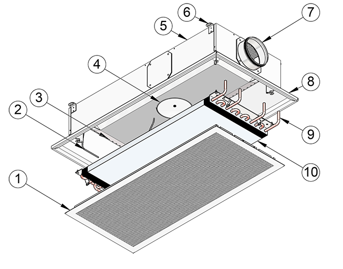
Fig.20. Halton Rex RXP
| No. | Part | Description | Note |
| 1 | Front panel |
|
Special colours available |
| 2 | Pressure measurement tube | Polyvinyl chloride | – |
| 3 | Nozzles | Galvanised steel | – |
| 4 | HAQ control |
|
– |
| 5 | Plenum |
|
– |
| 6 | Brackets | Galvanised steel | – |
| 7 | Spigot | Galvanised steel | – |
| 8 | Frame |
|
Special colours available |
| 9 | Connection pipes | Copper. Ø 12 mm with a wall thickness of 0.9–1.0 mm, fulfilling the requirements of European Standard EN 1057:1996. | – |
| 10 | Coil/Heat exchanger |
|
– |
Dimensions and weight
The dimensions are given in millimetres [mm].
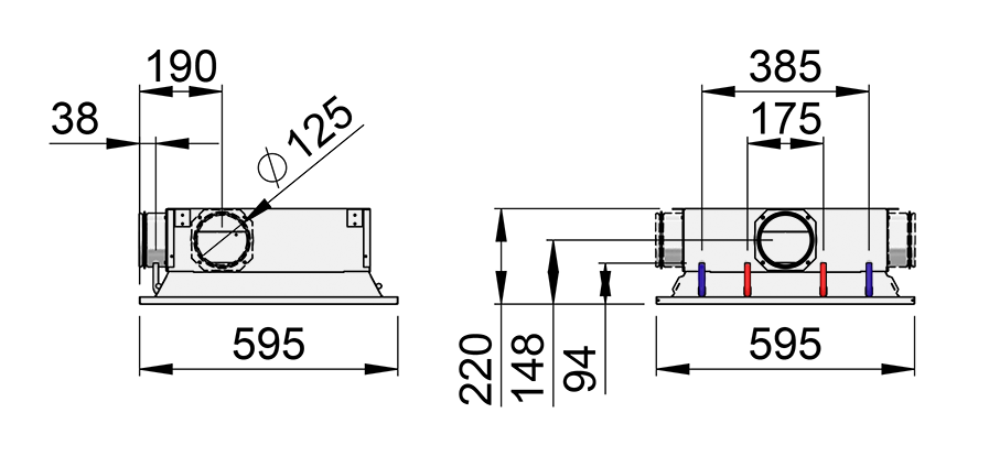
Fig.21. Halton Rex RXP, Standard model dimensions (RXP/S-600)
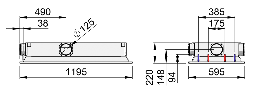
Fig.22. Halton Rex RXP, Standard model dimensions (RXP/S-1200)
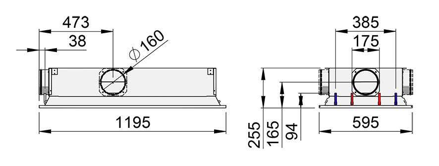
Fig.23. Halton Rex RXP, Standard. Flexible and Autonomic models dimensions (RXP/S, RXP/F-1200 or RXP/A-1200)
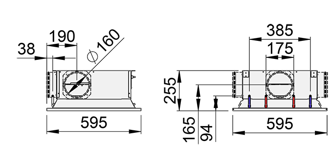
Fig. 24. Halton Rex RXP, Flexible and Autonomic models dimensions (RXP/F-600 or RXP/A-600)
Weight
Halton Rex RXP, Standard model
| Product | CN model | Dry mass (excl. water) [kg] | Water volume [l] |
| RXP/S-*- 600 | NA | 10.5 | 0.5 |
| MA | 11.4 | ||
| M1 | 11.6 | ||
| RXP/S-*- 1200 | NA | 20.9 | 1.2 |
| MA | 21.8 | ||
| M1 | 22.1 |
* Nozzle type, see section Order code.
Halton Rex RXP, Flexible and Autonomic model
| Product | CN model | Dry mass (excl. water) [kg] | Water volume [l] |
| RXP/F-F- 600 or RXP/A-F-600 | MA | 16.5 | 0.5 |
| M1 or M2 | 17.0 | ||
| RXP/F-F- 1200 or RXP/A-F-1200 |
MA | 30.4 | 1.2 |
| M1 or M2 | 31.0 |
Specification
Active chilled beam with CAV/VAV airflow function and four-directional air distribution, used for cooling, heating, and ventilation in suspended ceilings, fulfilling the following requirements:
Function
- Three product models with adjustable airflow using manual CAV or motorised VAV actuators
- Standard product model equipped with manual CAV or motorized (0…10 VDC) VAV actuators for boost airflow control and pressure dependent operation
- Flexible product model equipped with manual CAV or motorised (0…10 VDC) VAV actuators for 0-100% airflow control and pressure dependent operation
- Autonomic product model equipped with motorised (0…10 VDC or Modbus RTU/BACnet MSTP) VAV actuators for 0-100% airflow control and pressure independent operation
- Throw pattern expanded to corners automatically in higher airflow settings maintaining uniform supply air throw length.
- Flexible and Autonomic product models can be equipped with Halton Velocity Control (HVC) for adjusting room air velocity conditions individually on all four directions.
Structure
- Integral recirculation air path through the perforated front panel.
- Front panel removable to allow general maintenance and cleaning.
- Front panel removable without special tools.
- Four-directional air distribution.
- Unit width 595 mm, height 220 mm.
- Inlet duct diameter 125 mm or 160 mm.
- Duct connection position changeable without special tools.
- Measurement tap to allow airflow measurement.
- Pipework’s maximum operating pressure 1.0 MPa.
Materials
- Plenum, frame, and front panel manufactured from galvanised steel.
- All visible parts white, painted in RAL 9003, 20% gloss.
- All pipes manufactured from copper.
- Water connection pipes have a wall thickness of 0.9–1.0 mm.
- All pipe joints soldered.
- All pipe joints pressure-tested at the factory.
- Heat exchanger fins manufactured from aluminium.
Packaging and identification
- The product is protected by a removable plastic coating.
- The duct connection and pipe ends remain sealed during transport.
- The product is identified by a serial number printed on labels attached both to the product and the cardboard box.
Installation
When planning the orientation of the Halton Rex RXP chilled beam, the location of the supply air and water circuit connections must be taken into account. The supply air spigot can be at either side of the unit or at the same end with the water connections. The location can be easily changed on site, if needed.
The location of the actuator of the HAQ control (optional) must also be taken into account to ensure access to the airflow adjustment/actuator. The actuator is located in the middle of the left side of the unit. Similar way the location of the service hatch of the OMD control (manual or motorized models) must also be taken into account to ensure access to the airflow adjustment/actuator. See the details in section Operating principle.
The Halton Rex RXP chilled beam Standard/Flexible model can be installed directly to the ceiling surface (H = 220 mm /225 mm standard/flexible model). The Autonomic model can be installed 10 mm from the ceiling surface due to the space required by the actuator (H = 225 mm autonomic model + 10 mm space). Installation to the suspended ceiling can be done using threaded drop rods (8 mm). The brackets for ceiling installation are located at the sides of the unit.
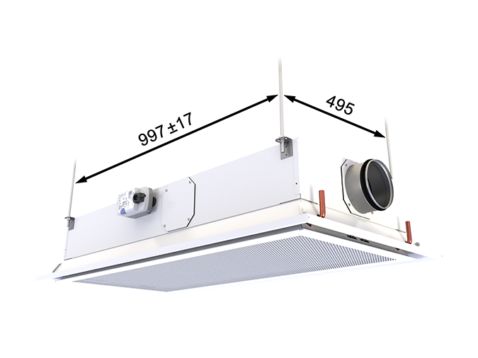
Fig. 25. Installation points of Halton Rex RXP 1200, Standard, Flexible and autonomic models. The location of the actuator in Halton Rex RXP 1200, Standard model
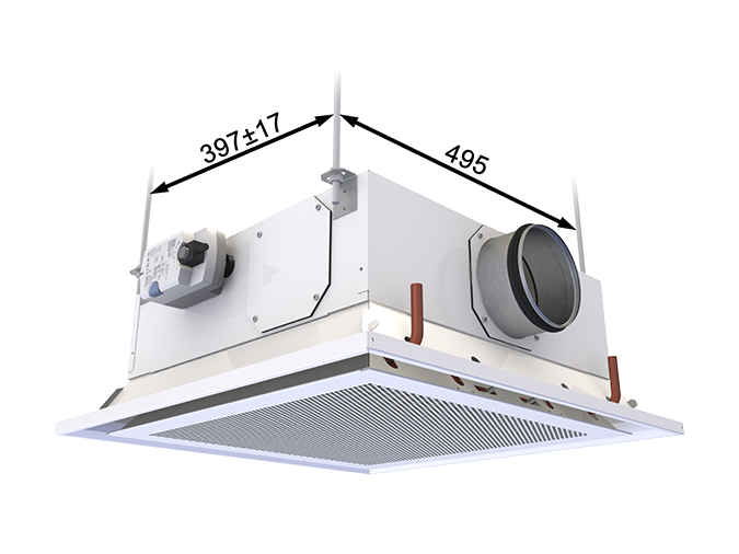
Fig. 26. Installation points and the location of actuator of Halton Rex RXP 600, Standard model
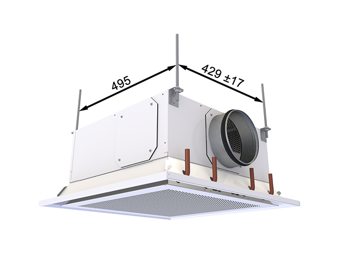
Fig. 27. Installation points and the location of actuator of Halton Rex RXP 600, Flexible and Autonomic models model
It is recommended that the main pipelines of the cooling and heating water circuits are installed above the level of the heat exchanger to enable venting of the pipework.
The maximum operating pressure for chilled/hot water pipework is 1.0 MPa.
Commissioning
Adjustment of the cooling capacity
The recommended cooling water mass flow rate is 0.02–0.10 kg/s, resulting in a temperature rise of 1–4°C in the heat exchanger. To avoid condensation, the recommended minimum inlet water temperature of the heat exchanger is 14–16°C.
Adjustment of the heating capacity
The recommended heating water mass flow rate is 0.01–0.04 kg/s, resulting in a temperature drop of 5–15°C in the heat exchanger. The maximum inlet water temperature of the heat exchanger is 35°C.
Balancing and control of water flow rates
The water mass flow rates of the Halton Rex RXP chilled beam are balanced with adjustment valves installed on the outlet side of the cooling water loops. The cooling capacity of the Halton Rex RXP chilled beam is controlled by regulating the water mass flow rate.
Adjustment of the supply airflow rate
With a Halton Rex RXP chilled beam standard model (RXP/S) that does not have the Halton Air Quality (HAQ) control, the airflow depends on the chamber pressure and the selected nozzle. With the HAQ control included, also the position of the HAQ control must be taken into account. The k factors are given in the table below.
With a Halton Rex RXP chilled beam Flexible model (RXP/F) the position of the OMD control must be taken into account according to the table below.
The chamber pressure (RXP/S) or the OMD pressure (RXP/F) can be measured from a measurement tap under
the front panel.
The total airflow rate is calculated using the formula below.
![]()
where
- qv Airflow rate in l/s or m³/h
- Δpm Measured pressure [Pa]
- k The k factor given as a function of mounting and diameter (see tables below)
Halton Rex RXP, Standard model (M=S)
| Position of HAQ control | Control signal voltage [V] | k factor [l/s], total airflow (Standard model) | |||||
| 600 | 1200 | ||||||
| C* | D* | E* | C* | D* | E* | ||
| 0/closed/no HAQ | 0-1 | 1.11 | 1.56 | 2.51 | 2.05 | 2.89 | 4.69 |
| 0.5 | 1.5 | 1.39 | 1.84 | 2.79 | 2.33 | 3.17 | 4.97 |
| 1 | 2 | 1.67 | 2.12 | 3.07 | 2.61 | 3.45 | 5.25 |
| 1.5 | 2.5 | 1.94 | 2.39 | 3.34 | 2.88 | 3.72 | 5.52 |
| 2 | 3 | 2.21 | 2.66 | 3.61 | 3.15 | 3.99 | 5.79 |
| 2.5 | 3.5 | 2.47 | 2.92 | 3.87 | 3.41 | 4.25 | 6,05 |
| 3 | 4 | 2.72 | 3.17 | 4.12 | 3.66 | 4.50 | 6.30 |
| 3.5 | 4.5 | 2.97 | 3.42 | 4.37 | 3.91 | 4.75 | 6.55 |
| 4 | 5 | 3.21 | 3.66 | 4.61 | 4.15 | 4.99 | 6.79 |
| 4.5 | 5.5 | 3.44 | 3.89 | 4.84 | 4.38 | 5.22 | 7.02 |
| 5 | 6 | 3.67 | 4.12 | 5.07 | 4.61 | 5.45 | 7.25 |
| 5.5 | 6.5 | 3.89 | 4.34 | 5.29 | 4.83 | 5.67 | 7.47 |
| 6 | 7 | 4.11 | 4.56 | 5.51 | 5.05 | 5.89 | 7.69 |
| 6.5 | 7.5 | 4.32 | 4.77 | 5.72 | 5.26 | 6.10 | 7,90 |
| 7 | 8 | 4.52 | 4.97 | 5.92 | 5.46 | 6.30 | 8.10 |
| 7.5 | 8.5 | 4.72 | 5.17 | 6.12 | 5.66 | 6,50 | 8.30 |
| 8 | 9 | 4.91 | 5.36 | 6.31 | 5.85 | 6.69 | 8.49 |
| 8.5 | 9.5 | 5.10 | 5.55 | 6.50 | 6.04 | 6.88 | 8.68 |
| 9 | 10 | 5.28 | 5.73 | 6.68 | 6.22 | 7.06 | 8.86 |
*Nozzle types: C = Medium, D = Large, E = Extra large
Table 3. Halton Rex RXP, Standard model: k-factors with different HAQ control positions in l/s
| Position of HAQ control | Control signal voltage [V] | k factor [m³/h], total airflow (Standard model) | |||||
| 600 | 1200 | ||||||
| C* | D* | E* | C* | D* | E* | ||
| 0/closed/no HAQ | 0-1 | 4.00 | 5.62 | 9.04 | 7.38 | 10.40 | 16.88 |
| 0.5 | 1.5 | 5.02 | 6.64 | 10.06 | 8.40 | 11.43 | 17.91 |
| 1 | 2 | 6.02 | 7.64 | 11.06 | 9.40 | 12.43 | 18.91 |
| 1.5 | 2.5 | 7.00 | 8.62 | 12.04 | 10.38 | 13.40 | 19.88 |
| 2 | 3 | 7.95 | 9.57 | 12.99 | 11.34 | 14.36 | 20.84 |
| 2.5 | 3.5 | 8.88 | 10.50 | 13.92 | 12.27 | 15.29 | 21.77 |
| 3 | 4 | 9.80 | 11.42 | 14.84 | 13.18 | 16.20 | 22.68 |
| 3.5 | 4.5 | 10.68 | 12.30 | 15.72 | 14.07 | 17.09 | 23.57 |
| 4 | 5 | 11.55 | 13.17 | 16.59 | 14.93 | 17.96 | 24.44 |
| 4.5 | 5.5 | 12.39 | 14.01 | 17,43 | 15.78 | 18.80 | 25.28 |
| 5 | 6 | 13.22 | 14.84 | 18.26 | 16.60 | 19.62 | 26.10 |
| 5.5 | 6.5 | 14.02 | 15.64 | 19.06 | 17.40 | 20.42 | 26.90 |
| 6 | 7 | 14.79 | 16.41 | 19.83 | 18.18 | 21.20 | 27.68 |
| 6.5 | 7.5 | 15.55 | 17.17 | 20.59 | 18.93 | 21.96 | 28.44 |
| 7 | 8 | 16.28 | 17.90 | 21.32 | 19.67 | 22.69 | 29.17 |
| 7.5 | 8.5 | 16.99 | 18.61 | 22.03 | 20.38 | 23.40 | 29.88 |
| 8 | 9 | 17.68 | 19.30 | 22.72 | 21.07 | 24.09 | 30.57 |
| 8.5 | 9.5 | 18.35 | 19.97 | 23.39 | 21.73 | 24.76 | 31.24 |
| 9 | 10 | 18.99 | 20.61 | 24.03 | 22.38 | 25.40 | 31.88 |
*Nozzle types: C = Medium, D = Large, E = Extra large
Table 4. Halton Rex RXP, Standard model: k-factors with different HAQ control positions in m3/h
Halton Rex RXP, Flexible model (M=F)
| Position of OMD control | Control signal voltage for electric actuator [V] | k factor [l/s], total airflow (Flexible model) | |
| 600 | 1200 | ||
| 0.0 | 0.12 | 0.14 | |
| 0.5 | 0.19 | 0.34 | |
| 1.0 | 0.27 | 0.54 | |
| 1.5 | 0.84 | 1.04 | |
| 2.0 | 1.42 | 1.55 | |
| 2.5 | 1.55 | 2.11 | |
| 3.0 | 1.69 | 2.66 | |
| 3.5 | 1.74 | 3.05 | |
| 4.0 | 1.78 | 3.44 | |
| 4.5 | 2.21 | 4.05 | |
| 5.0 | 2.64 | 4.67 | |
| 5.5 | 3.12 | 5.23 | |
| 6.0 | 3.60 | 5.79 | |
| 6.5 | 4.10 | 6.38 | |
| 7.0 | 4.60 | 6.97 | |
| 7.5 | 5.05 | 7.49 | |
| 8.0 | 5.50 | 8.02 | |
| 8.5 | 5.88 | 8.47 | |
| 9.0 | 6.25 | 8.92 | |
| 9.5 | 6.38 | 9.11 | |
| 10.0 | 6.51 | 9.30 | |
Table 5. Halton Rex RXP, Flexible model: k-factors with different OMD control positions in l/s
Note: For the k-factors of the products delivered before 30.06.2025, refer to the ” Halton Rex RXP, chilled beam – k-factors before 30.06.2025 ” document in the “Downloads” section..
| Position of OMD control | Control signal voltage for electric actuator [V] | k factor [m³/h], total airflow (Flexible model) | |
| 600 | 1200 | ||
| 0.0 | 0.42 | 0.51 | |
| 0.5 | 0.69 | 1.22 | |
| 1.0 | 0.97 | 1.94 | |
| 1.5 | 3.03 | 3.76 | |
| 2.0 | 5.10 | 5.59 | |
| 2.5 | 5.60 | 7.58 | |
| 3.0 | 6.09 | 9.57 | |
| 3.5 | 6.25 | 10.98 | |
| 4.0 | 6.42 | 12.39 | |
| 4.5 | 7.97 | 14.59 | |
| 5.0 | 9.52 | 16.80 | |
| 5.5 | 11.23 | 18.81 | |
| 6.0 | 12.95 | 20.83 | |
| 6.5 | 14.76 | 22.96 | |
| 7.0 | 16.58 | 25.09 | |
| 7.5 | 18.20 | 26.97 | |
| 8.0 | 19.82 | 28.86 | |
| 8.5 | 21.16 | 30.48 | |
| 9.0 | 22.50 | 32.11 | |
| 9.5 | 22.98 | 32.79 | |
| 10.0 | 23.45 | 33.48 | |
Table 6. Halton Rex RXP, Flexible model: k-factors with different OMD control positions in m3/h
Note: For the k-factors of the products delivered before 30.06.2025, refer to the ” Halton Rex RXP, chilled beam – k-factors before 30.06.2025 ” document in the “Downloads” section.
Halton Rex RXP, Autonomic model (M=A)
| Control signal voltage for electric actuator [V] | k factor [l/s], total airflow (Autonomic model) | |
| 600 | 1200 | |
| 0.0 | 0.08 | 0.21 |
| 0.5 | 0.24 | 0.43 |
| 1.0 | 0.40 | 0.64 |
| 1.5 | 0.89 | 1.01 |
| 2.0 | 1.38 | 1.37 |
| 2.5 | 1.51 | 1.76 |
| 3.0 | 1.65 | 2.16 |
| 3.5 | 1.69 | 2.58 |
| 4.0 | 1.73 | 3.01 |
| 4.5 | 2.01 | 3.38 |
| 5.0 | 2.29 | 3.76 |
| 5.5 | 2.73 | 4.23 |
| 6.0 | 3.18 | 4.70 |
| 6.5 | 3.64 | 5.23 |
| 7.0 | 4.09 | 5.75 |
| 7.5 | 4.51 | 6.27 |
| 8.0 | 4.93 | 6.79 |
| 8.5 | 5.31 | 7.28 |
| 9.0 | 5.69 | 7.77 |
| 9.5 | 6.05 | 8.22 |
| 10.0 | 6.40 | 8.68 |
Table 7. Halton Rex RXP, Autonomic model: k-factors with different OMD control positions in l/s
Note: For the k-factors of the products delivered before 30.06.2025, refer to the ” Halton Rex RXP, chilled beam – k-factors before 30.06.2025 ” document in the “Downloads” section.
| Control signal voltage for electric actuator [V] | k factor [m³/h], total airflow (Autonomic model) | |
| 600 | 1200 | |
| 0.0 | 0.29 | 0.75 |
| 0.5 | 0.86 | 1.53 |
| 1.0 | 1.44 | 2.31 |
| 1.5 | 3.21 | 3.62 |
| 2.0 | 4.98 | 4.94 |
| 2.5 | 5.45 | 6.35 |
| 3.0 | 5.92 | 7.77 |
| 3.5 | 6.07 | 9.30 |
| 4.0 | 6.22 | 10.84 |
| 4.5 | 7.23 | 12.18 |
| 5.0 | 8.23 | 13.53 |
| 5.5 | 9.84 | 15.23 |
| 6.0 | 11.44 | 16.93 |
| 6.5 | 13.09 | 18.82 |
| 7.0 | 14.74 | 20.71 |
| 7.5 | 16.24 | 22.58 |
| 8.0 | 17.74 | 24.45 |
| 8.5 | 19.11 | 26.20 |
| 9.0 | 20.49 | 27.95 |
| 9.5 | 21.77 | 29.59 |
| 10.0 | 23.05 | 31.23 |
Table 8. Halton Rex RXP, Autonomic model: k-factors with different OMD control positions in m3/h
Note: For the k-factors of the products delivered before 30.06.2025, refer to the ” Halton Rex RXP, chilled beam – k-factors before 30.06.2025 ” document in the “Downloads” section.
Example 1:
The measured static chamber pressure is 70 Pa for RXP/S-E-600, and the position of the HAQ control is 3. The total airflow rate is 4.12*√(70) ≈ 34.3 l/s.
Example 2:
The OMD pressure measured from the measurement tap in RXP/F-F-600 S3 is 75 Pa. RXP/F-F-600 S3 is equipped with the manual actuator. The positions of the manual actuator can be moved with the metal rod shown in Fig. 28. The measured distance to the tip of metal rod is 40 mm. For calculating the total airflow rate, the k-value is taken from Table 4 (measured distance rounded to closest value in table), and calculated with the equation 0.82*√75 ≈ 7 l/s.
Fig. 28. Adjustment of the manual actuator in Halton Rex RXP, Flexible model
Order code
RXP/M-S-L-E; SP-TC-CT-CN-VC-CO-ZT
| Main options | |
| M = Model | |
| F | Flexible |
| A | Autonomic |
| S | Standard |
| S = Nozzle type | |
| C | Medium |
| D | Large |
| E | Extra large |
| F | Flex |
| L = Length [mm] | 600 or 1200 |
| E = Duct connections | |
| S2 | Straight (Ø125) |
| R2 | Right (Ø125) |
| L2 | Left (Ø125) |
| S3 | Straight (Ø160) |
| R3 | Right (Ø160) |
| L3 | Left (Ø160) |
| Other options and accessories | |
| SP = System package | |
| N | No |
| Y | Yes |
| TC = Cooling/Heating functions (coil type) | |
| C | Cooling |
| H | Cooling and heating |
| CT = Connection type (air and water) | |
| S | Air and water at the same end |
| O | Air and water connections at the opposite ends |
| CN = Control type | |
| NA | Not assigned |
| MA | Manual |
| M1 | Motorised (0…10 VDC) |
| M2 | Motorised (Modbus RTU/BACnet MSTP) |
| VC = Velocity control (HVC) | |
| N | No |
| Y | Yes |
| CO = Colour | |
| SW | Signal white (RAL 9003) |
| X | Special colour (RAL xxxx) |
| ZT = Tailored product | |
| N | No |
| Y | Yes (ETO) |
| Sub product (ordered separately) | |
| System package | Halton Workplace WRA |
| Room exhaust VAV damper | Halton Max MOC |
| Room exhaust VAV damper | Halton Max MUC |
Order code example
RXP/S-E-1200-S2, SP=N, TC=C, CT=S, CN=NA, VC=N, CO=SW, ZT=N
Downloads
-
Halton Rex RXP – Chilled beam (CAV/VAV)
Data
en
-
Halton Rex RXP – Installation, commissioning and maintenance guide
Data
English (en) -
Eurovent Certification for Chilled Beams
Data
English (en) -
Environmental Product Declaration (EPD) – Halton Rex RE6, REE, RXP (chilled beams)
Data
English (en) -
Halton Rex RXP – k-factors before 30.06.2025
Data
English (en) -
Halton Rex RXP – Technical description
Data
English (en) -
Halton Rex RXP – Tekninen kuvaus
Data
Suomi (fi) -
Halton Rex RXP – Teknisk beskrivning
Data
Svenska (sv) -
Halton Rex RXP – Description technique
Data
Français (fr)
"*" indicates required fields
Halton CaBeam – Chilled beam for exposed wall installation
product
Halton CaBeam – Chilled beam for integrated installation
product
Halton CaBeam – Chilled beam for recessed installation
product
Halton CBH – Chilled beam
product
Halton CHB – Chilled beam
product
Halton CPA – Passive chilled beam
product
Halton CSW – Swirl comfort unit
product
Halton Rex R6W – Variable air volume chilled beam (VAV)
product
Halton Rex RE6 – Chilled beam
product
Halton Rex REE – Chilled beam
product
Halton Rex REO – Chilled beam (VAV)
product
Halton Rex REW – VAV chilled beam
product
Halton Rex RXP – Chilled beam (CAV/VAV)
product

Halton Vita VPR – Hygienic chilled beam
product

NEW! Halton CaBeam REC – For Passenger and Crew Cabins
product
NEW! Halton Rex REP – Passive chilled beam
product

NEW! Halton Rex RSI – Slim induction unit
product