Product / Halton CaBeam/Integrated
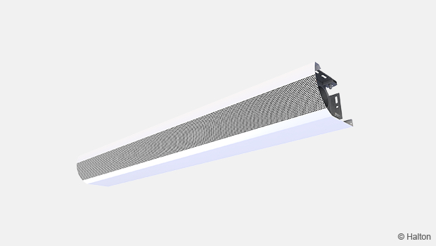
Halton CaBeam – Chilled beam for integrated installation
Halton CaBeam is a cooling, heating, and ventilation solution specifically designed to provide the best indoor comfort for demanding marine applications such as cabins on cruise ships and passenger ferries or living quarters on offshore substations.
Specification
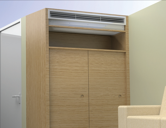
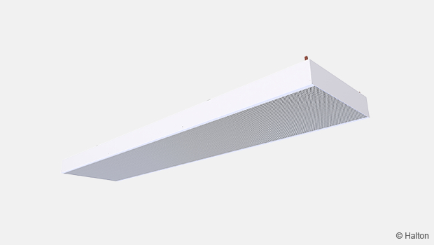
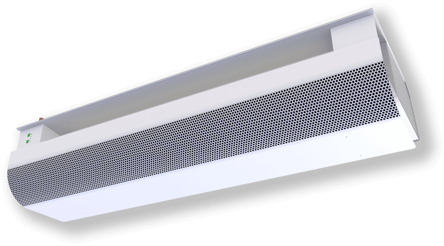
The Halton CaBeam is a cabin ventilation solution specifically designed for silent cabin comfort with sophisticated air treatment and control. The Halton CaBeam is available as an exposed, recessed or integrated installation.
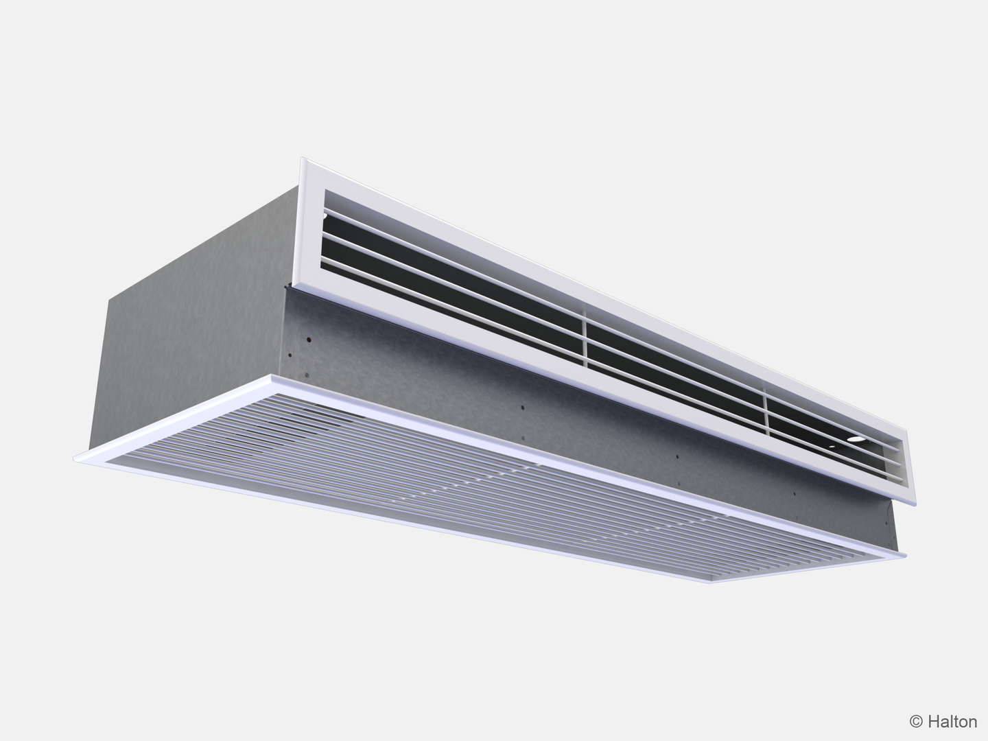
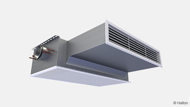
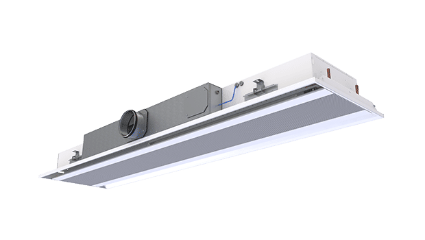
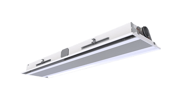
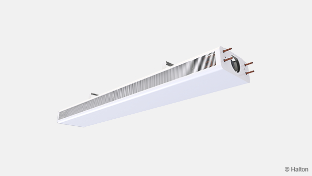
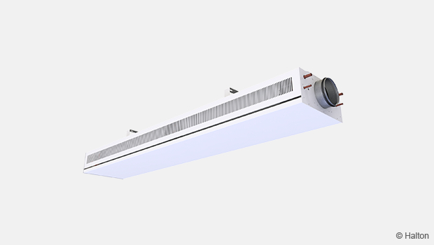
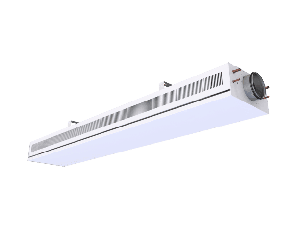
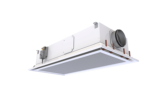
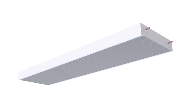
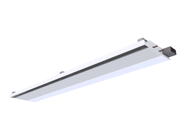
The integrated CaBeam unit is an active chilled beam solution designed for bulkhead and enclosed installation with return and supply air grilles for demanding marine applications.
The active chilled beam system employs fins to help heat and cool. The system is effective to the point where outdoor air can be mixed with the indoor air without any traditional air conditioning (such as heating, cooling, humidifying, or dehumidifying), allowing the building/ship to meet its “minimum outdoor air” air quality requirements.
The active chilled beam system requires much less energy to achieve the same heating and cooling effect as a traditional HVAC system.
The beam acts as a radiator chilled by recirculated water. The warm air rises and is cooled by the chilled beam; once it is cooled, the air falls back to the floor, where the cycle starts over. The ventilation air is delivered to the beam by a central air-handling system via ductwork.
Overview
- The supply and return air grilles are openable and removable for maintenance
- The inlet duct connection is modifiable and can be located at the right, left, or middle of the supply-air plenum. When there is an integrated fan, there is no option for a connection in the middle
- The heat exchanger of the beam is oriented such that the water connections can be on either the right or left side of the beam
- All pipes are manufactured from copper, connection pipes with a wall thickness of 0.9–1.0 mm fulfilling the European Standard EN 1057:1996. The fins of the heat exchanger are manufactured from aluminium or copper as an option. The heat exchanger is factory pressure-tested. The maximum operating pressure of chilled/hot water pipework is 1.0 MPa
- The supply air ductwork connection is D125 mm
Tailoring
Important notice
The Halton CaBeam units can be tailored to customer demands according to the needed integration and requirements. Dimensions, capacities, and functionality details can be modified to project-specific. An advanced digital room temperature control completes the solution.
Materials
| PART | MATERIAL | FINISHING |
| Return air grille | Pre-painted galvanised steel |
Polyester-epoxy-painted White RAL 9003 20% gloss* |
| Supply air grille | Aluminium | Polyester-epoxy-painted White RAL 9003 20% gloss* |
| Casing | Galvanised steel | |
| Supply air plenum | Galvanised steel | |
| Coil pipes | Copper | |
| Coil fines | Aluminium | Copper as an option |
*) Special colours available
Features
The cooling philosophy of the beam is based on dry cooling.
Controls and functionality are designed to eliminate the risk of condensation and to provide the highest energy-efficiency possible. Cabin door or openable window can be equipped with switches to indicate an open/close position and connected to the Halton CaBeam automation.
The system can communicate with the operating crew for IEQ, as well as, energy-efficiency and is suitable for network communication (selected parameters).
Function
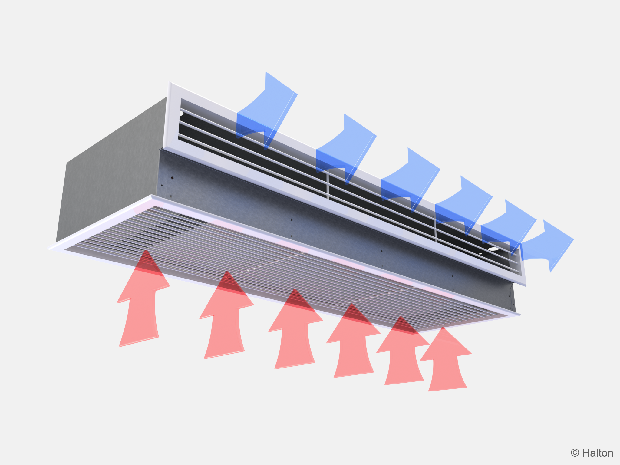
The primary supply air enters the plenum of the active chilled beam, from where it is diffused into the room through nozzles and a supply grille on the front side of the beam. The supply air nozzle jets efficiently induce ambient room air through the lower return air grille and the heat exchanger, where it is either cooled or heated. The combined air jet is directed along the ceiling surface.
Three different nozzle sizes are available to enable various supply airflow rates. The nozzle plates are inter-changeable to account for layout or room change.
Installation
Easy installation can be ensured in a prefabricated cabin.
The manufacturing method and innovative, compact design allow units to be modified for any situation.
Design Criteria
- Room design temperature 24°C / 50% RH
- Fresh air rate 50-75 m3/h
Nozzle pressure 150-200 Pa - Sensible cooling power 300-1500 W
- Heating power 500-1200 W
- Noise level 25-30 dB(A), boost <35 dB(A)
- Supply and exhaust to design values, 14 dm3/s (50 m3/h)
- Chilled water flow to 0,100 dm3/s (360 dm3/h)
- Chilled water inlet temperature 15°C
- Chilled water outlet temperature 17°C
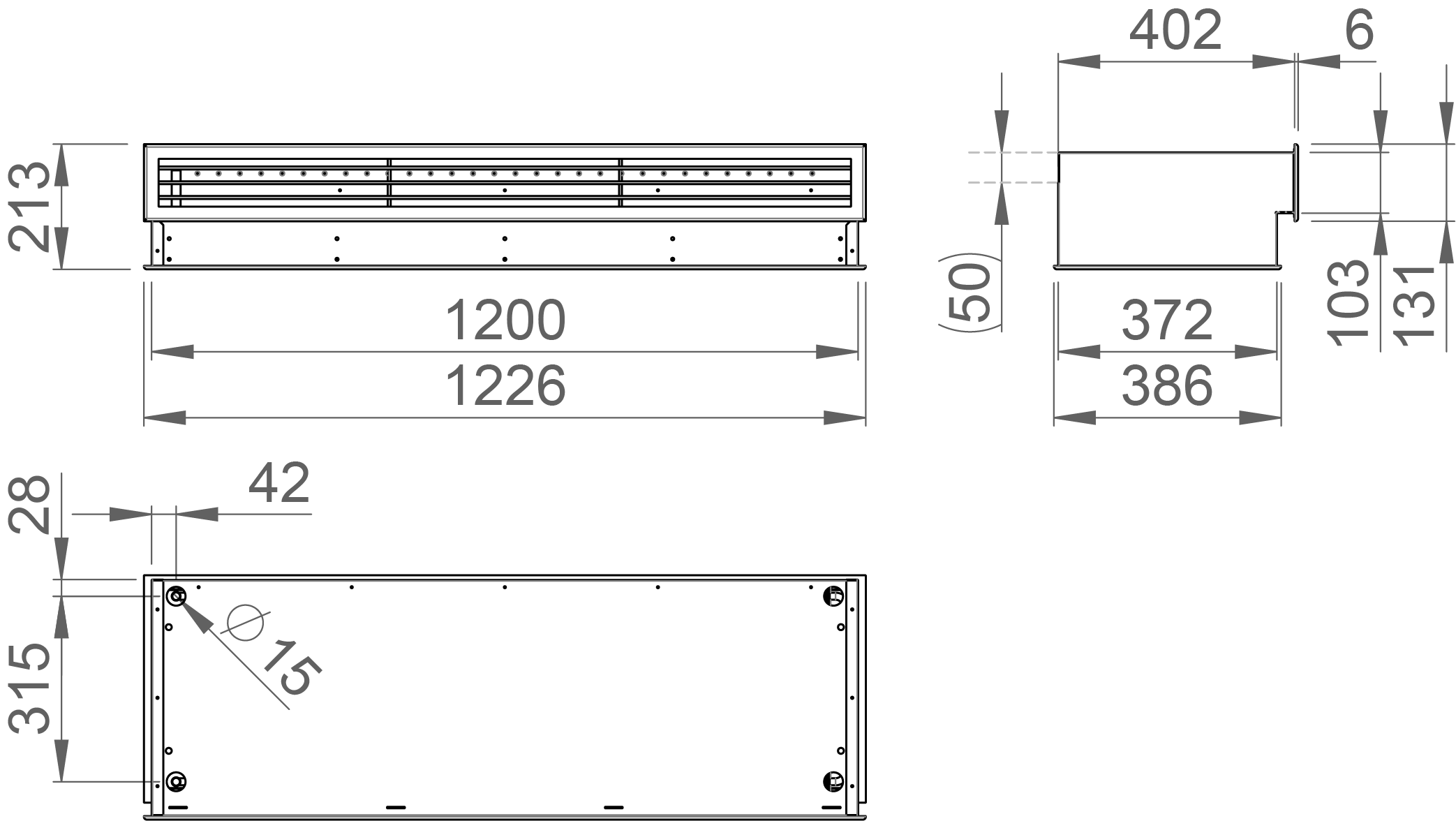
Dimensions and Weight
Adjustment
Cooling
The recommended cooling water mass flow rate is 0.02-0.10 kg/s, resulting in a temperature rise of 1-4°C in the heat exchanger. To avoid condensation, the recommended inlet water temperature of the heat exchanger is over 14-16°C.
Heating
The heating of the cabin is done by an electric heater in the primary air duct. Heating power in the normal cabin is typically 1-1,2 kW and capillary thermostat with manual reset is in close proximity of heater. Control of heater must be verified because in some cases there has been “leak” in control triac.
Heating with water (option)
The recommended heating water mass flow rate is 0.01-0.04 kg/s, resulting in a temperature drop of 5-15°C in the heat exchanger. The recommended temperature of the inlet water for the heat exchanger is 35-40°C.
Balancing and control of water flow rates
Balance the water-flow rates of the chilled beam with the standard control valve by selecting the desired Kvs value in the valve body. When using an automatically balancing combination valve, set the desired water flow rate in the valve body, and verify the pressure difference (min. 16 across the valve. Regulating the water mass flow rate controls the cooling and heating capacity of the chilled beam.
Adjustment of supply airflow rate
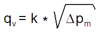
Each chilled beam is equipped with a measurement tap for static pressure measurement, which enables fast and accurate measurement of the rate of supply-air flow through the beam. The airflow rate is calculated using the formula.
K value is determined according the table below:
K value is determined according the table below:
| NOZZLE | WIDTH | k (l/s) | k (m3/h) |
| A | 1000 | 2,14 | 7,71 |
| A | 1200 | 2,83 | 10,20 |
| A | 1400 | 3,59 | 12.91 |
| B | 1000 | 2,93 | 10,55 |
| B | 1200 | 3,90 | 14,06 |
| B | 1400 | 4,97 | 17,91 |
| C | 1000 | 4,00 | 14,40 |
| C | 1200 | 5,39 | 19,41 |
| C | 1400 | 6,94 | 24,99 |
Servicing
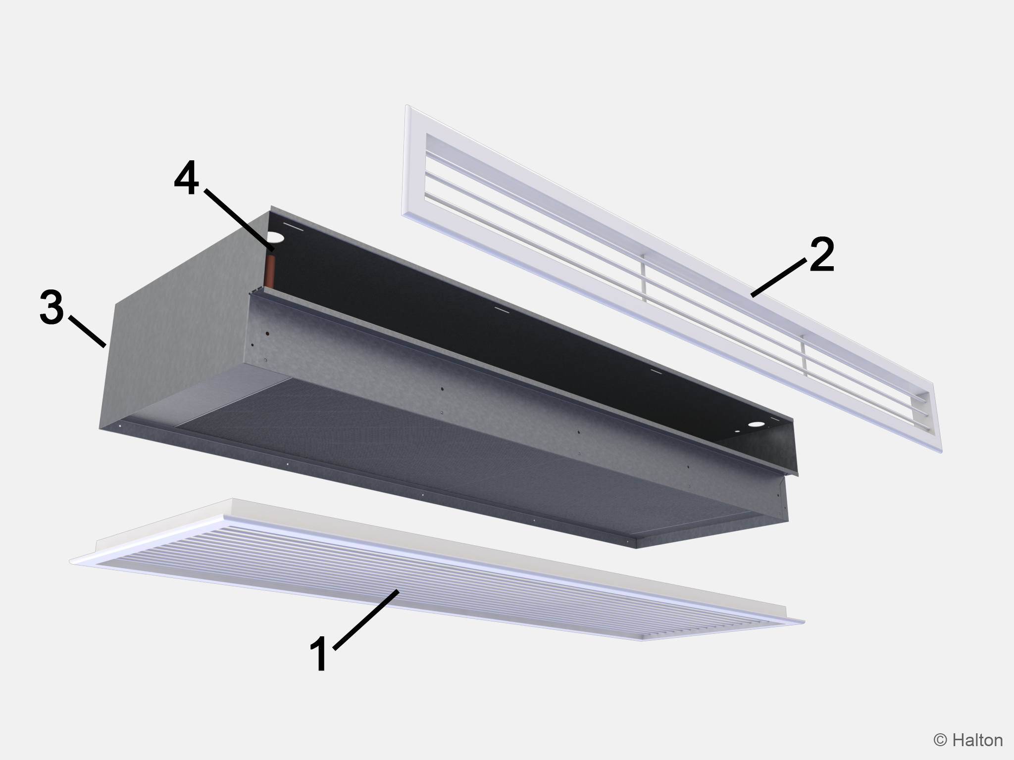
Code description
- Return air grille
- Supply air grille
- Supply air connection
- Chilled water pope connections
Open the return air grille of the chilled beam. Clean the finned coils of the heat exchanger with a vacuum cleaner, taking care not to damage the finned coils. Clean the return and supply air grilles with a damp cloth. Check at regular intervals that the actuators and water-flow control valves are working.
Downloads
Request for Quotation
"*" indicates required fields
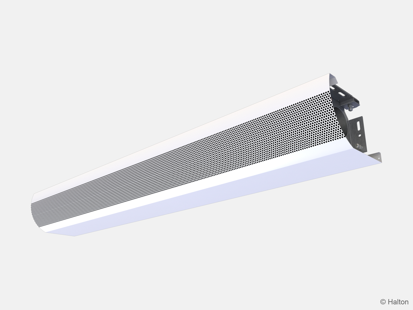
Halton CaBeam – Chilled beam for exposed wall installation
product
Halton CaBeam – Chilled beam for integrated installation
product
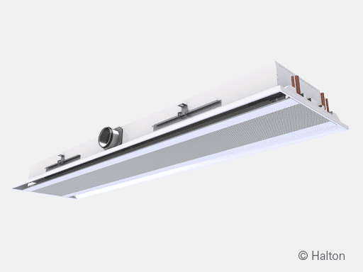
Halton CaBeam – Chilled beam for recessed installation
product
Halton CBH – Chilled beam
product
Halton CHB – Chilled beam
product
Halton CPA – Passive chilled beam
product
Halton CSW – Swirl comfort unit
product
Halton Rex R6W – Variable air volume chilled beam (VAV)
product
Halton Rex RE6 – Chilled beam
product
Halton Rex REE – Chilled beam
product
Halton Rex REO – Chilled beam (VAV)
product
Halton Rex REW – VAV chilled beam
product
Halton Rex RXP – Chilled beam (CAV/VAV)
product

Halton Vita VPR – Hygienic chilled beam
product
NEW! Halton CaBeam REC – For Passenger and Crew Cabins
product
NEW! Halton Rex REP – Passive chilled beam
product
NEW! Halton Rex RSI – Slim induction unit
product