Product / CBH
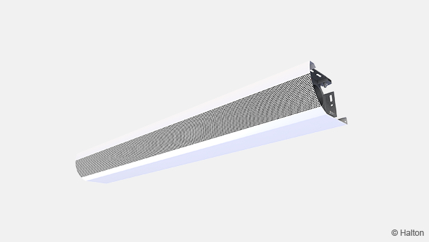
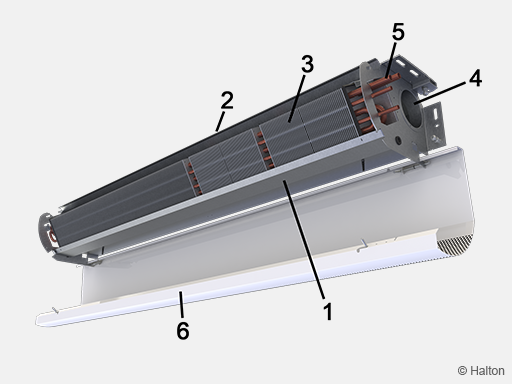
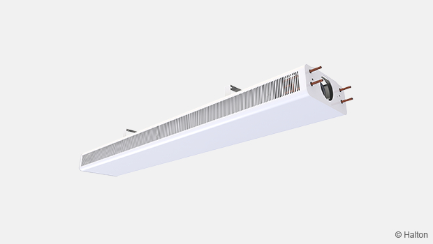
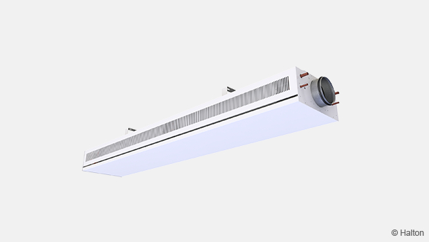
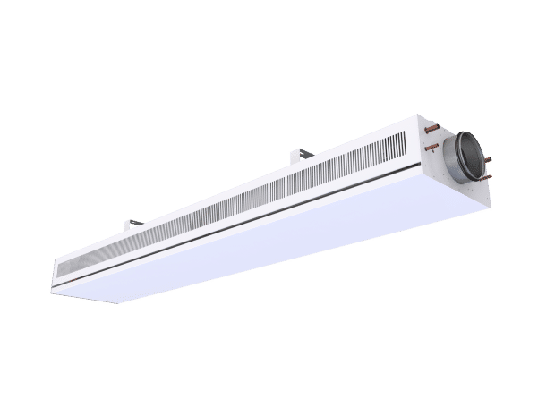
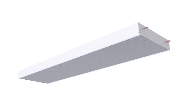
Halton CBH – Chilled beam
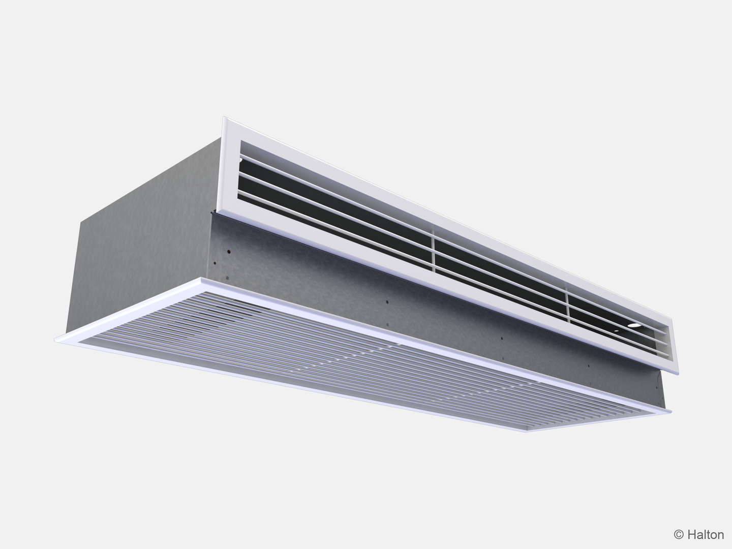
This corner positioned chilled beam is very quiet and well suited for hotel rooms.
- Combined cooling, heating, and supply air unit for exposed wall installation
- Limited need for maintenance, due to simple and hygienic principle of operation
Overview
- Combined cooling, heating and supply air unit for exposed wall installation
- Limited need for maintenance, due to simple and hygienic principle of operation
Product models and accessories
- Model with combined cooling and heating coil
- Options for chilled/hot water pipe connection locations
- Coil with venting valve
Halton chilled beams are certified by Eurovent Certita.

Dimensions
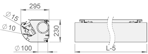
| Coil length | 1500,1600…4700 |
| L-5 | 1795,1895…4995 |
| kg/m | 10 |
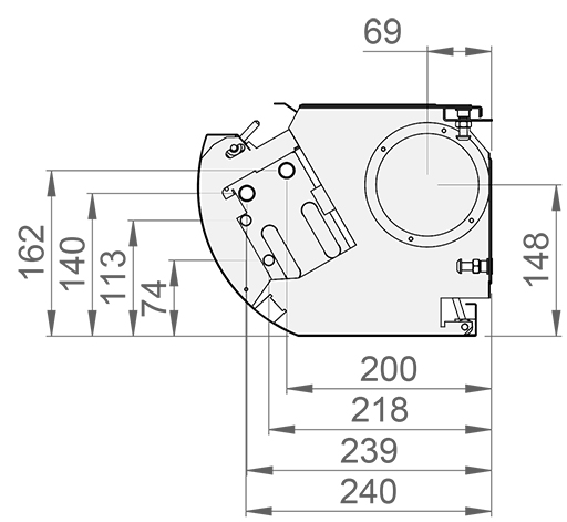
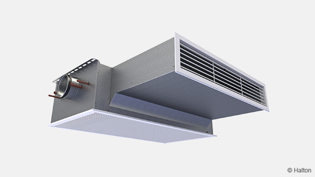
Location of the pipe connections
Material
| Part | Material | Finishing | Note |
| Front panel | Pre-painted galvanised steel |
Polyester-painted, White (RAL 9003, 20% gloss) |
Polyester-epoxy-painted Special colours available |
| Supply air plenum | Galvanised steel | – | – |
| Brackets | Galvanised steel | – | – |
| Coil pipes | Copper | – | – |
| Coil fins | Aluminium | – | – |
Cooling/heating water pipe connections are Cu15/Cu10 with a wall thickness of 0.9-1.0 mm fulfilling the European Standard EN 1057:1996.
The maximum operating pressure of chilled/hot water pipework is 1.0 MPa.
The supply air ductwork connection is D100 mm.
Accessories
| Accessory/model | Code | Description | Note |
| Combined cooling and heating coil |
TC = H or F | H = Coil with hot water circulation F = Coil with hot water circulation and air venting valves |
Cooling/heating copper water pipe connestions are Ø 15/10 mm |
| Coil equiped with valves for venting |
TC = D or F | D = Coil with cold water circulation and air venting valves F = Coil with hot water circulation and air venting valves |
Cooling/heating copper water pipe connestions are Ø 15/10 mm |
| Water pipe connections |
WD = S or O | S = straight connection O = pipe connection of the heat exchanger at the opposite end from the supply air connection |
|
| Duct cover | Made upon request, please contact sales for details |
Lenghts: 800, 900, …2500 mm |
Pre-painted galvanised steel, Polyester-painted white (RAL 9003, 20% gloss) |
Function
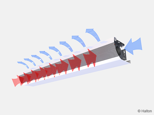
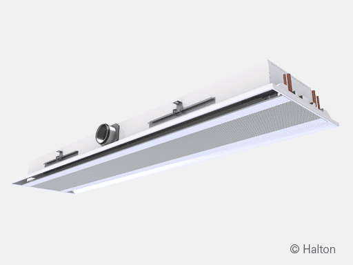
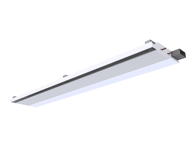
The supply air enters the plenum of the active chilled beam, from which it is diffused into the room through nozzles and the supply slot located on the top of the beam.
The air nozzle jets efficiently induce flow of ambient room air through the heat exchanger, where it is either cooled or heated.
The supply air jet is directed horizontally along the ceiling surface.
Two different nozzle sizes are available to enable different supply airflow rates.
The cooling and heating capacities of the chilled beam are controlled by regulating the water flow rate according to the control signal of the room temperature controller.
The Halton CBH active chilled beam is designed for exposed installation next to the wall.
Installation
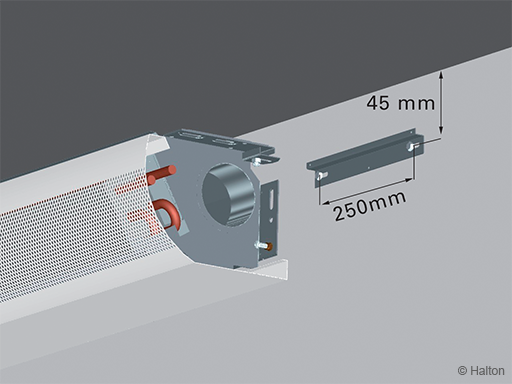
Fasten the unit to the wall using two assembly brackets, included in the delivery.
Adjust the beam horizontally and vertically to the desired position by using the two adjustment screws. The beam installation can be secured with screws through pre-drilled holes in the beam.
Install the main pipelines of the cooling and heating water loops above the level of the chilled beam to enable the venting of the pipework.
The supply air duct and pipe connection locations are specified when the product is ordered.
However, due to the symmetrical design, the supply air duct and pipe connection locations can be, when necessary, changed at the installation site:
- remove the access plug and remount it in the other end of the beam
- loosen the four fixing screws, then turn around and reassemble the heat exchanger, finally screwing in the fixing screws.
Adjustment
Cooling
The recommended cooling water mass flow rate is 0.03…0.10 kg/s, resulting in a temperature rise of 1…3 °C in the heat exchanger.
To avoid condensation, the recommended inlet water temperature of the heat exchanger is 14…16 °C.
Heating
The recommended heating water mass flow rate is 0.01…0.04 kg/s, resulting in a temperature drop of 5…15 °C in the heat exchanger.
The recommended inlet water temperature of the heat exchanger is 35…45 °C.
Balancing and control of water flow rates
The water flow rates of the beam are balanced by installing the balancing valves in the outlet water pipes of the cooling and heating water circuits.
Cooling and heating output of the beam are controlled by regulating water mass flow rates. The mass flow rate can be controlled with either an ON/OFF valve or proportionally with a 2- or 3-way valve.
Adjustment of supply airflow rate
Each beam is equipped with a measurement tap for static pressure measurement, which enables fast and accurate measurement of the supply airflow rate.
The airflow rate is calculated with the formula below.
| Model | Nozzle | k |
| CBH/F, CBH/K | 3 | 0.73 |
| CBH/G, CBH/M | 4 | 1.04 |
Servicing
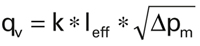
Code description
1. Front panel
2. Supply air plenum
3. Heat exchanger
4. Female supply air connection
5. Pipe connections
6. Duct cover
The active chilled beam Halton CBH with its openable construction facilitates fast and easy cleaning of the supply air plenum and heat exchanger. In beams longer than 2500 mm, the front panel can be opened in two sections.
Clean the front panel using a damp cloth.
Clean the heat exchanger using a vacuum cleaner, taking care not to damage the aluminium fins of the coil.
The supply air plenum has an access plug on the back end of the beam for cleaning the plenum.
Specification
The active chilled beam has an integral uni-directional air supply.
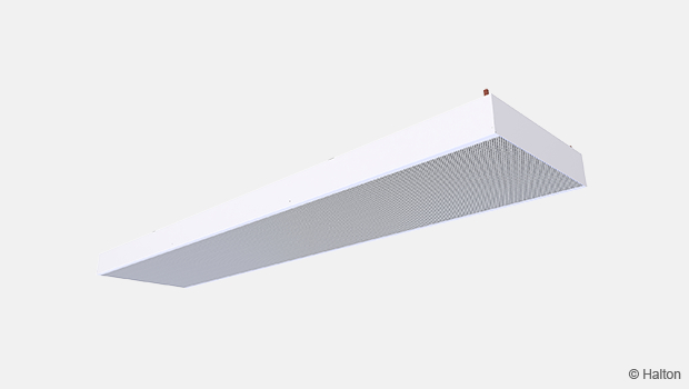
The supply air plenum is to be manufactured as a single construction free from joints. The front panel is openable and detachable for cleaning without using any special tools.
The active chilled beam is 295 mm wide and 230 mm high, with an inlet duct diameter of 100 mm.
The front panel is made of galvanised steel plate to a thickness of 0.75 mm.
All visible parts are painted to white RAL 9003 (20 % gloss).
The cooling heat exchanger consists of a coil with aluminium fins and six 15-mm pipes connected in series.
All joints are fully soldered and factory pressure tested.
Connection pipes are manufactured from copper, with a wall thickness of 0.9-1.0 mm.
Heating is incorporated within the heat exchanger by two 10-mm pipes connected in series.
The pipework s maximum rated operation pressure is 1.0 MPa.
Each beam is protected by a removable plastic coating.
The duct connection and pipe ends are sealed during transit.
Each beam is to be identifiable by a serial number printed on a label attached to the beam.
Order Code
CBH/F-E-L-C; WD-TC-CO-FP-ZT
S = Direction of supply patterns & nozzle type
F Uni-directional / Right / Nozzle 3
K Uni-directional / Left / Nozzle 3
G Uni-directional / Right / Nozzle 4
M Uni-directional / Left / Nozzle 4
E = Duct connection/Duct size/Damper
S1N Straight / 100 /Without damper
L = Total length
1800, +100, .., 5000
C = Effective length (Cooling coil length)
1500, +100, … , 4700
Other options and accessories
WD = Location of pipe connections
S Straight
O Opposite
TC = Cooling / Heating functions (Coil type)
C Cooling
H Cooling and heating
D Cooling only, venting valves
F Cooling+heating, venting valves
CO = Colour
SW Signal white (RAL9003)
X Special colour (RALxxxx)
FP = Front panel type
C Standard
N Without front panel
ZT = Tailored product
N No
Y Yes (ETO)
Code example
CBH/F-S1N-1800-1500, WD=S, TC=C, CO=SW, FP=C, ZT=N
Downloads
"*" indicates required fields
Halton CaBeam – Chilled beam for exposed wall installation
product
Halton CaBeam – Chilled beam for integrated installation
product
Halton CaBeam – Chilled beam for recessed installation
product
Halton CBH – Chilled beam
product
Halton CHB – Chilled beam
product
Halton CPA – Passive chilled beam
product
Halton CSW – Swirl comfort unit
product
Halton Rex R6W – Variable air volume chilled beam (VAV)
product
Halton Rex RE6 – Chilled beam
product
Halton Rex REE – Chilled beam
product
Halton Rex REO – Chilled beam (VAV)
product
Halton Rex REW – VAV chilled beam
product
Halton Rex RXP – Chilled beam (CAV/VAV)
product

Halton Vita VPR – Hygienic chilled beam
product
NEW! Halton CaBeam REC – For Passenger and Crew Cabins
product
NEW! Halton Rex REP – Passive chilled beam
product
NEW! Halton Rex RSI – Slim induction unit
product