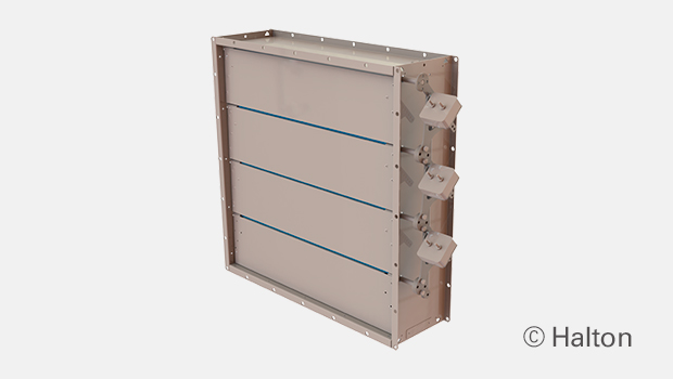
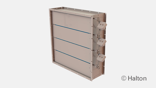
概述
- 焊连的外框可选材质为喷漆、镀锌或不锈钢。风叶为镀锌或不锈钢
- 适合水平和垂直安装的型号
- 通过ATEX/IECEx认证
- 闭合的阀防泄漏等级符合 EN 1751 2 级。测试尺寸为 1000X1000 mm
- 风叶包含硅胶密封,防止泄漏
- 每片风叶相互连接且同时开闭
- 可通过改变重锤的位置进行调节。重锤标配在右侧,也可选配左侧的重锤
- 阀门结构可适应的最大管道压力为 5000Pa,最大空气流速为 15m/s。如果管道压力过高,请联系浩盾船舶寻求最佳解决方案
Dimensions and Material Thickness
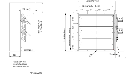
BLD non-return dampers meet international standards for both rectangular (width B 150-1200 mm and height H 150-1400 mm, 1mm division) and circular ducts (Ø100 – 1250 mm). Non-standard dimensions are available on request. Standard flange width 27 mm. Flanges and drilling also available according to ISO 15138 standards. Modular construction sizes up to 2400×2800 mm. Standard frame material thickness 3 mm. Blades made of two sheets, each being 0.8 mm thick (sandwich design).
BLD, general drawing
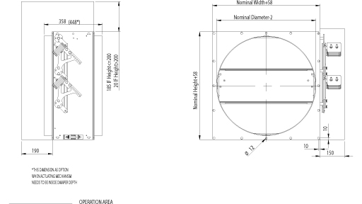
BLD drawing, circular connections
BLD circular, with connection flanges
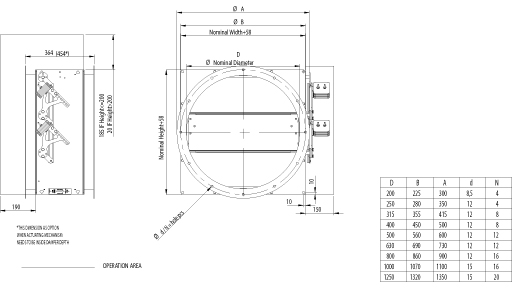
Material and Finishing
| PART | MATERIAL | FINISHING |
| Frame | Carbon steel | Painted or galvanised |
| Frame | Stainless steel EN 1.4301 (AISI304), EN 1.4404 (AISI316L), EN 1.4432 (AISI316L) | – |
| Blades | Steel | Galvanised |
| Blades | Stainless steel EN 1.4301 (AISI304), EN 1.4404 (AISI316L), EN 1.4432 (AISI316L) | – |
| Maintenance-free bearings | Stainless steel EN 1.4404 (AISI316L) / Option: bronze bearings available | – |
| Shafts | Stainless steel EN 1.4404 (AISI316L) | – |
Standard frame material thickness 3 mm.
Blades are made of two sheets, each of being 0.8 mm thick.
Product Models and Accessories
- Models for horizontal and vertical installation available
- Circular connection pieces are available.
- Standard construction places weights on the right hand side. Weights on the left hand side available as an option.
Operation Principles
Non-return damper will allow one-way airflow in the ductwork. This feature is based on imbalanced blades. When the pressure in the ductwork drops below minimum opening force required, the blades close and seal the duct to prevent backflow. The minimum opening force can be adjusted with weights. Minimum opening pressure 30 Pa.
Weights
Weights of standard BLD dampers (kg). Frame thickness 3 mm.
| H/HEIGHT (mm) |
B / WIDTH (mm) | |||||||||||
| 150 | 200 | 300 | 400 | 500 | 600 | 700 | 800 | 900 | 1000 | 1100 | 1200 | |
| 150 | 8 | 9 | 11 | 13 | 15 | 16 | 18 | 20 | 22 | 24 | 25 | 27 |
| 200 | 10 | 12 | 12 | 14 | 16 | 19 | 20 | 22 | 24 | 26 | 28 | 29 |
| 300 | 12 | 13 | 15 | 18 | 20 | 21 | 24 | 26 | 29 | 31 | 34 | 35 |
| 400 | 14 | 15 | 18 | 20 | 23 | 25 | 28 | 30 | 33 | 36 | 37 | 40 |
| 500 | 17 | 17 | 21 | 24 | 27 | 29 | 32 | 35 | 37 | 40 | 43 | 45 |
| 600 | 19 | 20 | 24 | 26 | 29 | 32 | 36 | 39 | 42 | 45 | 47 | 51 |
| 700 | 21 | 23 | 26 | 30 | 33 | 37 | 40 | 43 | 47 | 50 | 53 | 57 |
| 800 | 22 | 24 | 27 | 33 | 36 | 40 | 43 | 47 | 51 | 54 | 58 | 62 |
| 900 | 26 | 28 | 32 | 36 | 39 | 44 | 48 | 52 | 56 | 60 | 63 | 67 |
| 1000 | 28 | 30 | 34 | 39 | 43 | 48 | 51 | 55 | 60 | 64 | 68 | 72 |
| 1100 | 31 | 33 | 38 | 42 | 47 | 51 | 56 | 60 | 65 | 70 | 72 | 78 |
| 1200 | 33 | 35 | 40 | 45 | 50 | 54 | 59 | 64 | 69 | 74 | 78 | 84 |
| 1300 | 36 | 38 | 44 | 48 | 53 | 58 | 64 | 69 | 74 | 79 | 83 | 89 |
| 1400 | 38 | 40 | 46 | 51 | 56 | 62 | 67 | 73 | 78 | 83 | 88 | 94 |
| D2 ØD | WEIGHT |
| mm | kg |
| 100 | 12 |
| 160 | 12 |
| 200 | 15 |
| 250 | 17 |
| 315 | 21 |
| 400 | 26 |
| 500 | 36 |
| 630 | 45 |
| 800 | 63 |
| 1000 | 87 |
| 1250 | 116 |
Weights stated above include counter weights.
Installation
Installation on wall or roof.
At wall installation the blade orientation must always be in horizontal plane.
Copies of Installation, Operation and maintenance manuals are available from Halton Marine Sales offices and distributors.
Product Code
| (S)=Shape of Connection | |||||||
| (A) Circular (D1) | |||||||
| (B) Circular (D1) outlet | |||||||
| (C) Circular (D2) | |||||||
| (R) Rectangular | |||||||
| (W)=Width | |||||||
| Min=150 mm | |||||||
| Max=1200 mm | |||||||
| (H)=Height | |||||||
| Min=150 mm | |||||||
| Max=1400 mm | |||||||
| (D)=Diameter | |||||||
| Min=100 mm | |||||||
| Max=1250 mm | |||||||
| (SF)=Flange Option | |||||||
| (H0) Connection flange in circular connections | |||||||
| (H1) Connection + loose flange in circular connections | |||||||
| (HA) Flanges (2 sides) | |||||||
| (HB) Counter flanges (2 sides) | |||||||
| (HC) Counter flange (1 side) | |||||||
| (N0) (N0) ISO 15138 flange drilling CO+CIR | |||||||
| (N1) ISO 15138 flange drilling CO+LO+CIR | |||||||
| (NA) Not Assigned (circular connection) | |||||||
| (NR) ISO 15138 flange drilling | |||||||
| (DF)=Deep Frame Model | |||||||
| (N) No | |||||||
| (Y) Yes | |||||||
| (LM)=Left Hand Model | |||||||
| (N) No | |||||||
| (Y) Yes | |||||||
| (CW)=Counter Weights Included | |||||||
| (Y) Yes | |||||||
| (MA)=Material Blades | |||||||
| (AS) Stainless steel 0.8 mm EN1.4404 | |||||||
| (CS) Carbon steel 0.75 mm | |||||||
| (LS) Stainless steel 0.8 mm EN1.4432 | |||||||
| (SS) Stainless steel 0.8 mm EN1.4301 | |||||||
| (FM)=Frame Material | |||||||
| (A3) Stainless steel 3 mm EN1.4404 | |||||||
| (C3) Carbon steel 3 mm EN1.4404 | |||||||
| (L3) Stainless steel 3 mm EN1.4432 | |||||||
| (S3) Stainless steel 3 mm EN1.4301 | |||||||
| (FI)=Finishing | |||||||
| (HG) Hot galvanized | |||||||
| (NA) Not Assigned (acid treatment) | |||||||
| (PN) Painting | |||||||
| (BM)=Bearing Material | |||||||
| (BR) Bronze | |||||||
| (AS) Stainless steel EN1.4404 | |||||||
| Code example | |||||||
| BLD/R-1000-1000,SF=HA,DF=N,LM=N,CW=Y,MA=CS,FM=C3,FI=HG,BM=AS,ZT=N | |||||||
Downloads
"*" indicates required fields


