Product / BLD
BLD – Non-return damper
Halton BLD non-return dampers are used in offshore and marine applications to prevent backflow through ventilation ductwork.
Overview
- Fixed frame in painted, galvanized or stainless steel. Blades of galvanized or stainless steel.
- Models for horizontal or vertical installation
- Available as ATEX/IECEx certified
- Leakage class (EN1751:2014) of closed damper up to class 2. Details available from Halton.
- Blades contain silicone seal to lower the leakage through blades
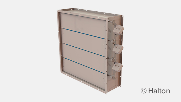
- Blades linked and open in parallel
- Adjustable by changing the position of counterweights. Standard construction places weights on the right hand side, weights on the left hand side available as an option.
- Maximum duct pressure for damper construction 5000 Pa and maximum air velocity 15 m/s. In case of high duct pressure, contact Halton Marine for finding the most suitable solution
- Temperature operation range up to +100°C, optionally up to +180°C
Specification
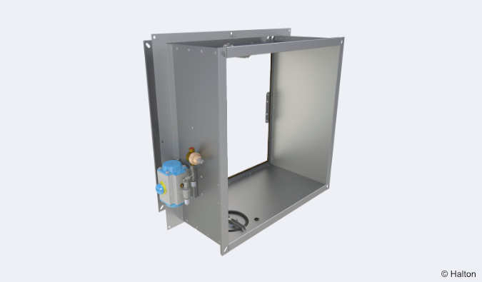
Halton BLD non-return dampers are used in offshore and marine applications to prevent backflow through ventilation ductwork system. The BLD dampers do not need an actuator or motor. Non-return dampers can be installed in rectangular or circular ducts, horizontally or vertically. If required, they can easily be set by adjusting the weight of each damper/installation. When the blades are in the open position, the device does not cause significant pressure loss, noise or flow disturbance.
Dimensions and Material Thickness
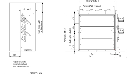
BLD non-return dampers meet international standards for both rectangular (width B 150-1200 mm and height H 150-1400 mm, 1mm division) and circular ducts (Ø100 – 1250 mm). Non-standard dimensions are available on request. Standard flange width 27 mm. Flanges and drilling also available according to ISO 15138 standards. Modular construction sizes up to 2400×2800 mm. Standard frame material thickness 3 mm. Blades made of two sheets, each being 0.8 mm thick (sandwich design).
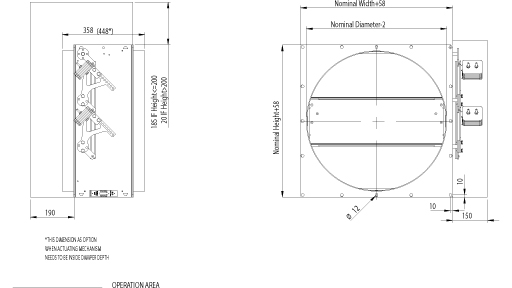
BLD, general drawing
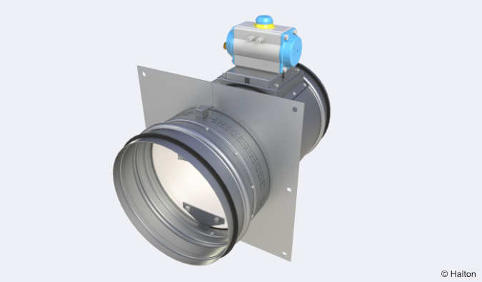
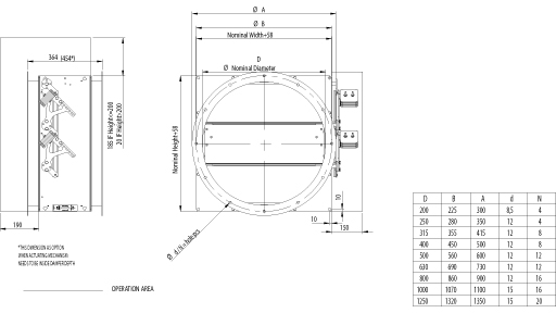
BLD drawing, circular connections
BLD circular, with connection flanges
Material and Finishing
| PART | MATERIAL | FINISHING |
| Frame | Carbon steel | Painted or galvanised |
| Frame | Stainless steel EN 1.4301 (AISI304), EN 1.4404 (AISI316L) | – |
| Blades | Steel | Galvanised |
| Blades | Stainless steel EN 1.4301 (AISI304), EN 1.4404 (AISI316L) | – |
| Maintenance-free bearings | Stainless steel EN 1.4404 (AISI316L) / Option: bronze bearings available | – |
| Shafts | Stainless steel EN 1.4404 (AISI316L) | – |
Standard frame material thickness 3 mm.
Blades are made of two sheets, each of being 0.8 mm thick.
Product Models and Accessories
- Models for horizontal and vertical installation available
- Circular connection pieces are available.
- Standard construction places weights on the right hand side. Weights on the left hand side available as an option.
Operation Principles
Non-return damper will allow one-way airflow in the ductwork. This feature is based on imbalanced blades. When the pressure in the ductwork drops below minimum opening force required, the blades close and seal the duct to prevent backflow. The minimum opening force can be adjusted with weights. Minimum opening pressure 30 Pa.
Weights
Weights of standard BLD dampers (kg). Frame thickness 3 mm.
| H/HEIGHT (mm) |
B / WIDTH (mm) | |||||||||||
| 150 | 200 | 300 | 400 | 500 | 600 | 700 | 800 | 900 | 1000 | 1100 | 1200 | |
| 150 | 8 | 9 | 11 | 13 | 15 | 16 | 18 | 20 | 22 | 24 | 25 | 27 |
| 200 | 10 | 12 | 12 | 14 | 16 | 19 | 20 | 22 | 24 | 26 | 28 | 29 |
| 300 | 12 | 13 | 15 | 18 | 20 | 21 | 24 | 26 | 29 | 31 | 34 | 35 |
| 400 | 14 | 15 | 18 | 20 | 23 | 25 | 28 | 30 | 33 | 36 | 37 | 40 |
| 500 | 17 | 17 | 21 | 24 | 27 | 29 | 32 | 35 | 37 | 40 | 43 | 45 |
| 600 | 19 | 20 | 24 | 26 | 29 | 32 | 36 | 39 | 42 | 45 | 47 | 51 |
| 700 | 21 | 23 | 26 | 30 | 33 | 37 | 40 | 43 | 47 | 50 | 53 | 57 |
| 800 | 22 | 24 | 27 | 33 | 36 | 40 | 43 | 47 | 51 | 54 | 58 | 62 |
| 900 | 26 | 28 | 32 | 36 | 39 | 44 | 48 | 52 | 56 | 60 | 63 | 67 |
| 1000 | 28 | 30 | 34 | 39 | 43 | 48 | 51 | 55 | 60 | 64 | 68 | 72 |
| 1100 | 31 | 33 | 38 | 42 | 47 | 51 | 56 | 60 | 65 | 70 | 72 | 78 |
| 1200 | 33 | 35 | 40 | 45 | 50 | 54 | 59 | 64 | 69 | 74 | 78 | 84 |
| 1300 | 36 | 38 | 44 | 48 | 53 | 58 | 64 | 69 | 74 | 79 | 83 | 89 |
| 1400 | 38 | 40 | 46 | 51 | 56 | 62 | 67 | 73 | 78 | 83 | 88 | 94 |
| D2 ØD | WEIGHT |
| mm | kg |
| 100 | 12 |
| 160 | 12 |
| 200 | 15 |
| 250 | 17 |
| 315 | 21 |
| 400 | 26 |
| 500 | 36 |
| 630 | 45 |
| 800 | 63 |
| 1000 | 87 |
| 1250 | 116 |
Weights stated above include counter weights.
Installation
Installation on wall or roof.
At wall installation the blade orientation must always be in horizontal plane.
Copies of Installation, Operation and maintenance manuals are available from Halton Marine Sales offices and distributors.
Product Code
(S)=Shape of Connection
(A) Circular (D1)
(B) Circular (D1) outlet
(C) Circular (D2)
(R) Rectangular
(W)=Width
Min=150 mm
Max=1200 mm
(H)=Height
Min=150 mm
Max=1400 mm
(D)=Diameter
Min=100 mm
Max=1250 mm
(SF)=Flange Option
(H0) Connection flange in circular connections
(H1) Connection + loose flange in circular connections
(HA) Flanges (2 sides)
(HB) Counter flanges (2 sides)
(HC) Counter flange (1 side)
(N0) (N0) ISO 15138 flange drilling CO+CIR
(N1) ISO 15138 flange drilling CO+LO+CIR
(NA) Not Assigned (circular connection)
(NR) ISO 15138 flange drilling
(DF)=Deep Frame Model
(N) No
(Y) Yes
(LM)=Left Hand Model
(N) No
(Y) Yes
(CW)=Counter Weights Included
(Y) Yes
(MA)=Material Blades
(AS) Stainless steel 0.8 mm EN1.4404
(CS) Carbon steel 0.75 mm
(SS) Stainless steel 0.8 mm EN1.4301
(FM)=Frame Material
(A3) Stainless steel 3 mm EN1.4404
(C3) Carbon steel 3 mm EN1.4404
(S3) Stainless steel 3 mm EN1.4301
(FI)=Finishing
(HG) Hot galvanized
(NA) Not Assigned (acid treatment)
(PN) Painting
(BM)=Bearing Material
(BR) Bronze
(AS) Stainless steel EN1.4404
Code example
BLD/R-1000-1000,SF=HA,DF=N,LM=N,CW=Y,MA=CS,FM=C3,FI=HG,BM=AS,ZT=N
Downloads
Request for Quotation
"*" indicates required fields