Skip to content

Product / VPA

VPA 辐射板

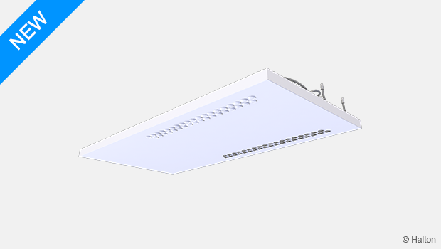
Halton Vita Patient Ava (VPA)是一个完整的病房解决方案,集成辐射制冷和加热,并结合了独特的保护气流模式。Halton VPA 为患者提供舒适的室内气候条件,为医务人员提供安全的工作环境。

Halton Vita Patient Ava 是 Halton Vita 患者解决方案的一部分。

  • 低而光滑的设计,表面卫生,易于清洁。
  • 自动化系统具有易于使用的界面,确保在不同操作模式下的灵活性和最佳功能。
Request a Quote

概览

Halton Vita Patient Ava (VPA)是一个完整的病房装置,集成辐射制冷和制热,并结合了独特的保护气流模式。Halton VPA 为患者提供舒适的室内气候条件,为医务人员提供安全的工作环境。 Halton Vita Patient Ava (VPA)是Halton Vita 患者解决方案的一部分。

应用

  • 医院病房

主要特点

  • 辐射制冷和制热,并带有送风分配,以满足舒适和最佳的室内气候条件。
  • 保护性气流模式,为患者和医务人员提供安全的环境。
  • 低而光滑的设计,表面卫生,易于清洁。
  • 适用于天花板整合暗装或明装
  • 病房操作模式控制的完整解决方案。
  • 自动化系统,易于使用的界面,可以确保在不同操作模式下的灵活性和最佳性能。

工作原理

The Halton Vita Patient Ava (VPA) 将送风分配和辐射板与自动化相结合,使其成为病房的完整解决方案。
辐射板用于确保个人的热舒适性。通过辐射板铜管里的水流,冷热量传导至铝板,铝板作为辐射表面将温度传递至周围环境。

保护气流模式

为了降低感染风险并加强对医务人员的保护,Halton Vita Patient Ava (VPA)提供了独特的保护气流模式。该解决方案通过产生一个来自送风的屏障来保护医务人员,同时保持患者的热舒适。

当配备Halton Vita 病房自动化系统和VAV变风量阀时,Halton Vita Patient Ava (VPA)具有三种不同的操作模式:

  • 空病房待机(分钟)—— 与有人时的(正常)操作模式下配置的气流速率相比,Halton Vita 病房自动化控制器可降低气流速率。
  • 有人时(正常),对于有一个或多个患者的房间 —— 根据病房中的患者数量配置气流速度,Halton Vita 病房自动化控制器保持配置的气流速度。
  • 增压(最大值),适用于医务人员或其他人员与患者在同一病房的情况——Halton Vita 病房自动化控制器可增加气流速度。

在增压操作模式下,送风气流旨在产生保护性气流模式,防止患者呼出的细菌进入医务人员的呼吸区。同时,新鲜、清洁的空气被带到医务人员的呼吸区。
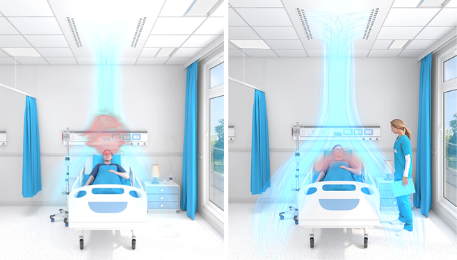
VPA protective airflow

Fig. 2. Protective airflow pattern. Left: Normal mode. Right: Boost mode with protective airflow pattern.

热舒适性

Halton Vita 病房自动化系统的设计可以使每个患者都能对房间进行单独控制,从而使患者能够根据自己的需求控制温度水平。温度水平通过调节铜管中循环水的流速和温度来控制。因此,患者的热舒适度得到了优化。如有必要,还可通过增加气流速度来增强制冷量。

制冷制热量

辐射板的冷却量根据EN 14240进行测量。安装类型(天花板一体化暗装或明装)会影响输出性能。因此,在Halton HIT设计软件中,可以检查每种情况下的制冷和制热量,应选择安装类型以获得更具体的输出数据。

辐射板的制热量根据EN 14037:2016进行测量。Halton辐射板的制热量已在经认证的第三方实验室进行测量,以满足EN 14037-2的要求。

Key technical data

Feature Description
Airflow rate 10…70 l/s
Dimensions 2400×1200 mm or 3000×1200 mm
Duct connection ø 160 mm
Cooling capacity Up to 785 W (Tr 24°C, Ts 18°C, qvair 70 l/s, Tw 15°C, qmwater 0.035
kg/s)
Heating capacity Up to 605 W (Tr 20°C, Ts 20°C, Tw 50°C, qmwater 0.030 kg/s)
Weight 36.8…67.1 kg (excl. water)

Features and options

Category Feature Options
Size Length
  • Nominal length 2400 mm
  • Nominal length 3000 mm
Width Nominal width 1200 mm
Cooling and
heating
Number of loops
  • 1 loop (cooling or heating)
  • 2 loops (cooling and heating)
Water valves and
actuators
  • Not included
  • Linear, 0…10 V
Automation System package
  • Not included
  • With integrated automation system
Airflow Nozzle diffuser Always included
Connection type
  • Plenum box with a manual airflow damper
  • Plenum box without a manual airflow damper
VAV damper
  • No VAV damper
  • With a VAV damper. Options:
    o Halton Max One Circular (MOC)
    o Halton Max Ultra Circular (MUC)

For information on the actuator options of these VAV
dampers, see Order code.

Finishing Colour White antibacterial epoxy polyester powder paint (RAL 9003).
Standard white as option.
Accessories Sound attenuator With or without sound attenuation.
For information on the options, see Order code.

For information on the order code, see Order code.

Halton Vita Patient Ava product models

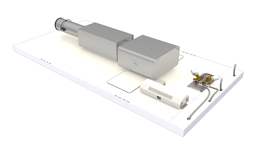
VPA_model_with_automation

Fig. 3. Halton Vita Patient Ava room unit with automation (a radiant panel equipped with a Halton Vita Room Automation controller unit, a VAV damper, a sound attenuator, a plenum box, and water valves and actuators)

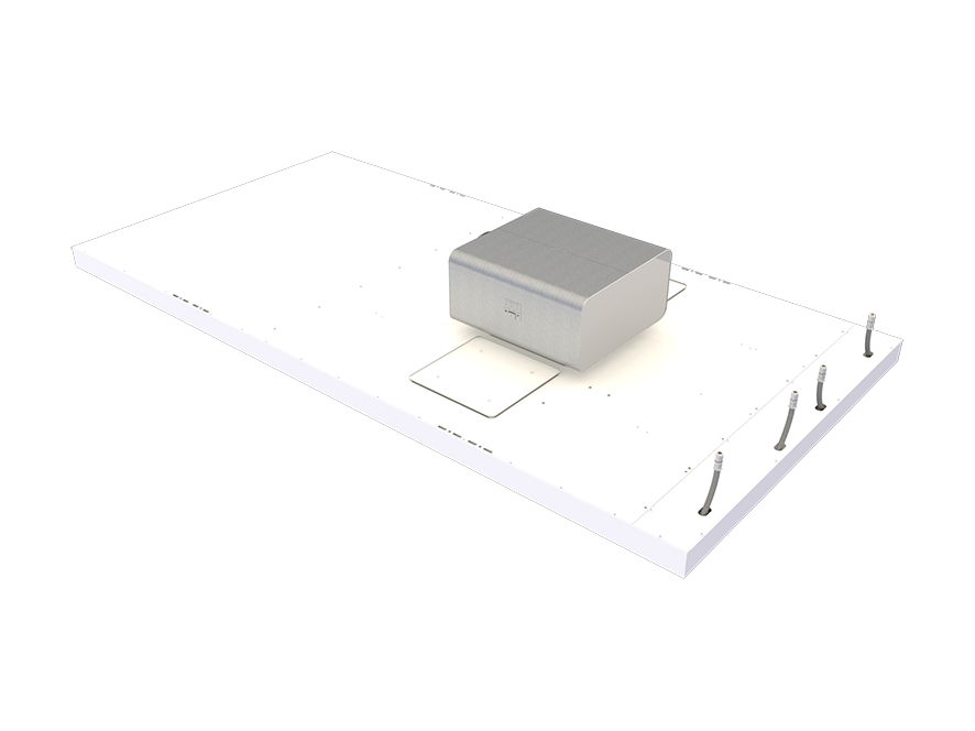
VPA_model_without_automation

Fig. 4. Halton Vita Patient Ava room unit without automation (a radiant panel equipped with a plenum box including a manual airflow damper)

System package

The system package should be selected in the Halton Vita Patient Ava (VPA) product order code when the product is intended to be equipped with Halton Vita VRA room automation system.

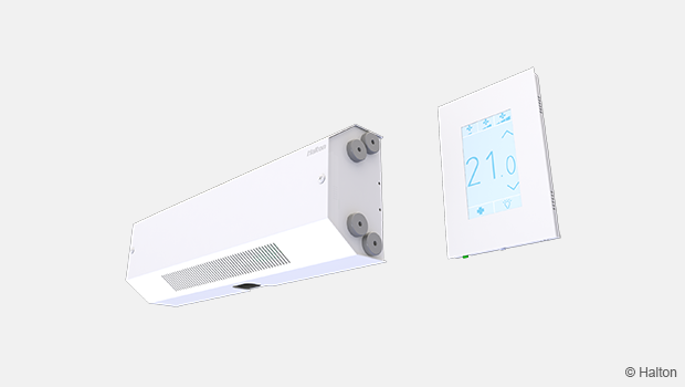
The package consists of a controller unit and a user panel used to adjust the ventilation airflow, room temperature, and lighting in a hospital patient room.

VRA control box_LPC_overview left_620_350

Fig 5. Automation control unit and a user panel

The controller unit is installed on top of the panel and the user panel on the wall.

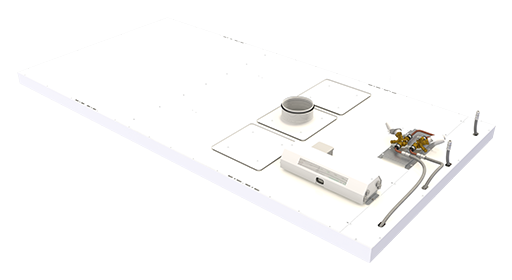
VPA - Location of system package components

Fig 6. Location of system package components

You can find more detailed information about the system package under Halton Vita VRA room automation product pages.

Specification

  • A room unit designed for hospital patient rooms.
  • Combines radiant cooling and heating with supply air distribution.
  • The room unit is equipped with an automation system that enables three different operating modes, airflow control, as well as the temperature and lighting control of the patient room.
  • The pre-programmed and pre-tested automation system includes a hygienic user panel for adjusting the operating mode, room temperature, and lighting of the room.
  • With the automation system and a VAV airflow damper, the room unit increases the airflow rate and provides an airflow pattern that protects the medical staff from bacteria exhaled by the patient.

Structure

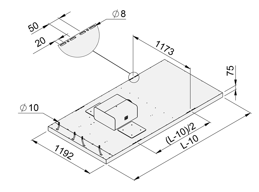
  • Unit length 2400 or 3000 mm.
  • Unit width 1200 mm, thickness 75 mm.
  • Inlet duct diameter 160 mm.
  • Pipework’s maximum operating pressure 1.0 MPa.
  • There are two inspection hatches to enable cleaning the air chamber of the unit.

Materials

  • Front panel manufactured from aluminium.
  • Duct connection and related parts manufactured from galvanised steel.
  • All visible parts painted. White antibacterial epoxy polyester powder paint (RAL 9003).
  • All pipes manufactured from copper.
  • All pipe joints soldered.
  • All pipe joints pressure-tested at the factory.

Packaging and identification

  • The visible surface of the product is protected by a removable plastic coating.
  • The duct connection and pipe ends remain sealed during transport.
  • The product is packed on a pallet.
  • The product is identified by a serial number printed on labels attached both to the product and the package.

Design information

When designing a patient room, consider the following:

  • To ensure the protective airflow pattern, the Halton Vita Patient Ava room unit should be installed above each patient bed in a patient room.
  • Are both cooling and heating functions needed?
    • The room unit can be equipped with one or two water loops. Typically, loop 1 is used for cooling and loop 2 for heating.
    • To enable individual temperature control for patients, it is recommended that the room unit is equipped with two water loops (cooling and heating) and Halton Vita Room Automation.
  • If a patient room has several beds, it is recommended that the airflow and temperature can be individually adjusted for each patient. This enables the protective airflow pattern for medical staff or other people around individual beds.
    • If needed, it is possible to control the whole room as one area. In this case, the airflow dampers are located in the main ducts of the room, not in the room unit branches.
  • Is it possible to open the windows in the room?
    • If it is possible to open the windows in the room, it is recommended that window switches are used. A window switch detects whether a window is open or closed. If the window is open, the cooling valve is closed to prevent condensation. The window switch is an accessory available separately and needs to be specified in the design documents.
  • How are the lights in the patient room controlled?
    • The Halton Vita Room Automation controller uses Digital Addressable Lighting Interface (DALI) for controlling the lighting: switching the lights on or off, dimming the lights, or controlling the lights in groups.

Installation

Halton Vita Patient Ava room units are suitable for ceiling-integrated and exposed ceiling installation.
To ensure the protective airflow pattern, the Halton Vita Patient Ava room unit should be installed above each patient bed in a patient room. The end with the water connections should come above the head end of the patient bed. The distance between the end wall and the unit should be 600 mm.

The required free height from the lowest point of the front panel to the ceiling is 341 mm.

Enough space must be reserved around the unit for maintenance. If there is a solid ceiling, there must be a service hatch close to the unit, to enable access to the top of the unit.

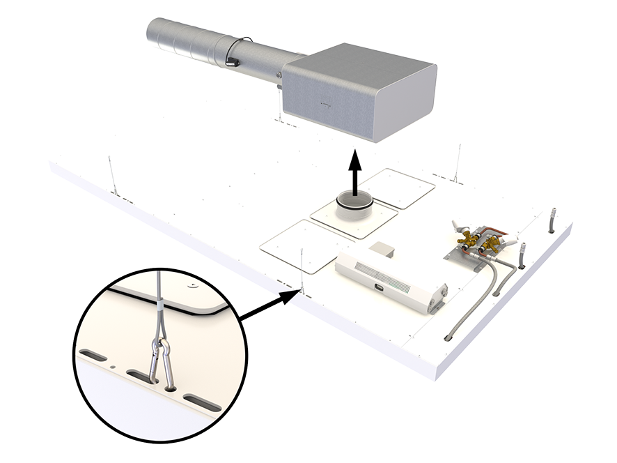
The unit is installed by suspending it from the ceiling using wires and snap hooks.

VPA_installation

Fig. 7. Halton Vita Patient Ava installation

NOTE: Wires, snap hooks and flexible hoses are not included in the delivery.

Commissioning

Airflow adjustment

To enable the protective airflow pattern, the nozzles are directed towards the longitudinal centre line of the room unit. If necessary, the direction of the nozzles can be adjusted.

Cooling

The recommended cooling water mass flow rate is 0.020…0.035 kg/s, resulting in a temperature rise of 1…3°C in the radiant panel. To avoid condensation, the recommended temperature of the inlet water is over the dew point temperature of the room.

Heating

The recommended heating water mass flow rate is 0.015…0.030 kg/s, resulting in a temperature drop of 3…10°C in the radiant panel. In typical rooms (room height up to 3 m), the usual recommended maximum temperature of the inlet water is 50°C due to a risk of the radiation asymmetry being too high.

Structure and materials

VPA_structure

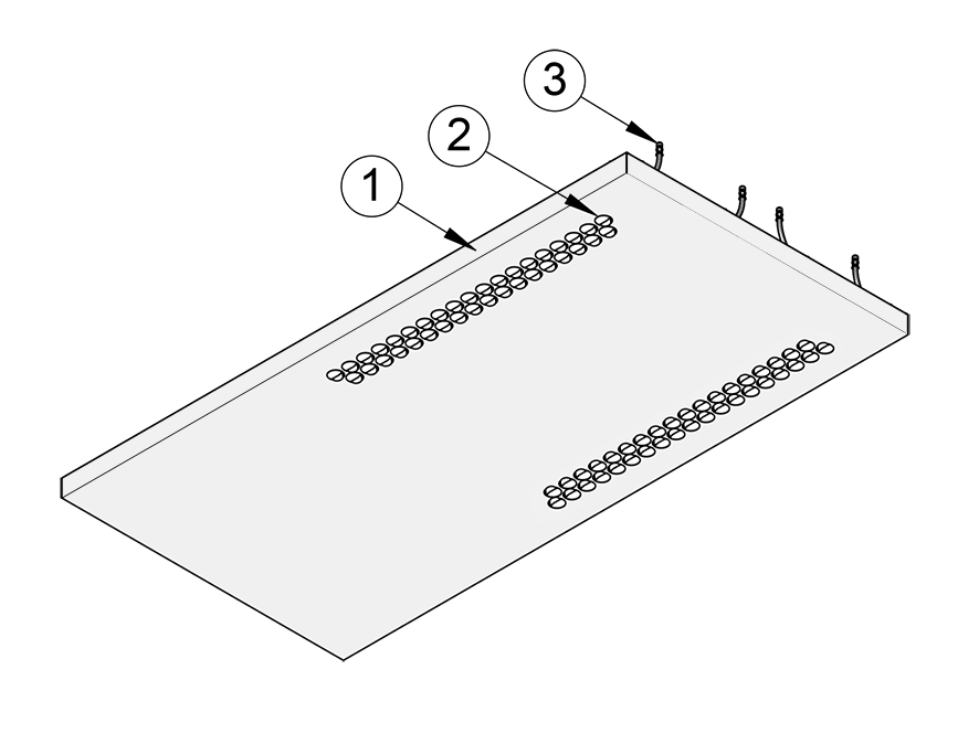
Fig. 8. Structure of Halton Vita Patient Ava room unit, bottom view

No. Part Description
1 Front panel Pre-painted aluminium. White antibacterial epoxy polyester powder paint
(RAL 9003). Standard white as option.
2 Air nozzles Plastic (polyacetal)
3 Radiant panel
connection pipes
Connection pipes with push-fit fittings: stainless steel, ø 10 mm

VPA_structure_top

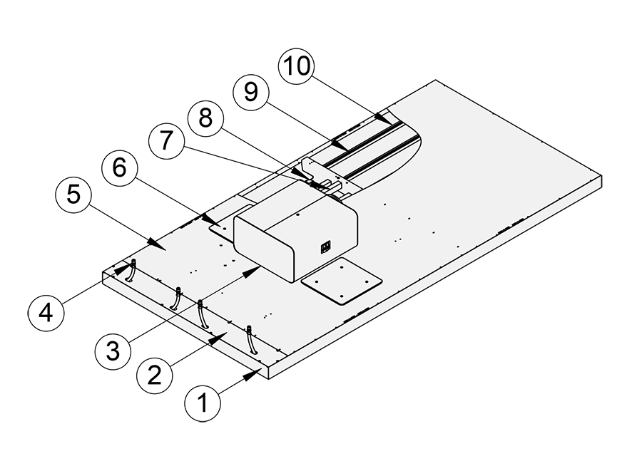
Fig. 9. Structure of Halton Vita Patient Ava room unit, top view

No. Part Description
1 Front panel Pre-painted aluminium. White antibacterial epoxy polyester powder paint
(RAL 9003). Standard white as option.
2 Cover plate Aluminium
3 Plenum box Galvanised steel, duct connection: ø 160 mm
4 Radiant panel
connection pipes
Connection pipes with push-fit fittings: stainless steel, ø 10 mm
5 Top cover plate Aluminium
6 Inspection hatches Galvanised steel
7 Sound absorption
material
Polyester fibre
8 Air nozzles Plastic (polyacetal)
9 Radiant panel
pipes
Copper, ø 10 mm
10 Pipe fixing profiles Aluminium

Dimensions and weight

VPA_dimensions

Fig. 10. Dimensions of Halton Vita Patient Ava room unit. L = 2400 or 3000 mm.

VPA_dimensions_side

Fig. 11. Dimensions of Halton Vita Patient Ava room unit, side view.

Weight

Unit length [mm] Number of water
loops
Panel without
automation, dry
mass [kg]
Panel with
automation, dry
mass [kg]
Water mass [kg]
2400 1 36.8 55 4.6
2400 2 40.7 59.9 6.7
3000 1 43.1 61.3 5.7
3000 2 47.9 67.1 8.4

Servicing

The front panel and other visible painted plates can be wiped using a damp cloth. The unit tolerates room disinfection with hydrogen peroxide.

There are two inspection hatches to enable cleaning the air chamber of the unit.

If installed exposed, it is recommended that the top of the unit is vacuumed.

For cleaning frequency, follow the maintenance schedule of the building.

Product selection examples

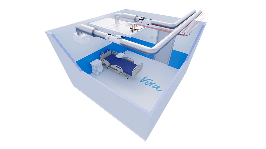
One VPA room unit controlled individually with a VRA controller in a one-patient
room

VRA_TD_prod_example_3

Description

In this configuration, the Halton Vita Room Automation (VRA) controller controls one Halton Vita Patient Ava (VPA) room unit. The VPA room unit has heating and cooling valves and a VAV damper. The system also includes a VRA user panel, a window switch, and an exhaust VAV damper. One VRA controller can individually control two VPA room units, and there can be several VRA controllers in a room.

Design criteria

  • One patient bed in the room
  • VPA room unit has heating and cooling valves
  • VPA room unit has a motorised VAV damper (MOC/MUC)
  • VPA room unit has an individual VRA controller
  • Exhaust airflow control with a motorised VAV damper (MOC/MUC)

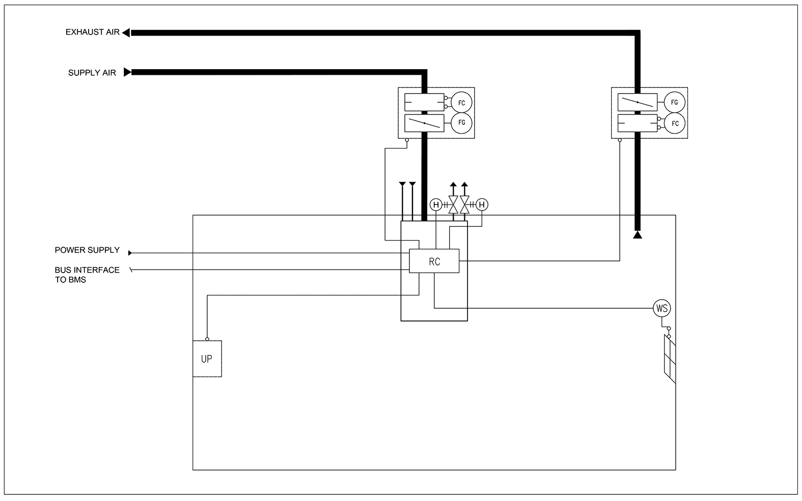
Schematic drawing

VRA_TD_prod_example_3_wiring

Fig. 12. Schematic drawing: One VPA room unit controlled individually with a VRA controller in a one-patient room

Code Equipment
UP VRA user panel
RC VRA controller unit
FG Airflow damper actuator
FC Airflow measurement
H Water valve actuator
WS Window switch

Order code examples for the system

  • 1 x VPA room unit with heating and cooling valves, VAV damper, and condensation sensor
    Code example:
    VPA-3000-1200,NL=2,SP=Y,ND=Y,CV=L1,CT=D,VD=MO,SA=H1,CO=SA
  • 1 x VRA controller unit with VRA user panel and window switch
    Code example:
    VRA/VPA-PA-VR-VC,CP=C1,LC=NA,CV=L1,FS=DC, WS=W1,EL=NA,ZT=N
  • 1 x MOC VAV damper with sound attenuator for exhaust
    Code example:
    MOC/G-160,MA=CS,CU=EM,FS=DS,SA=H1,RH=NA,ZT=N

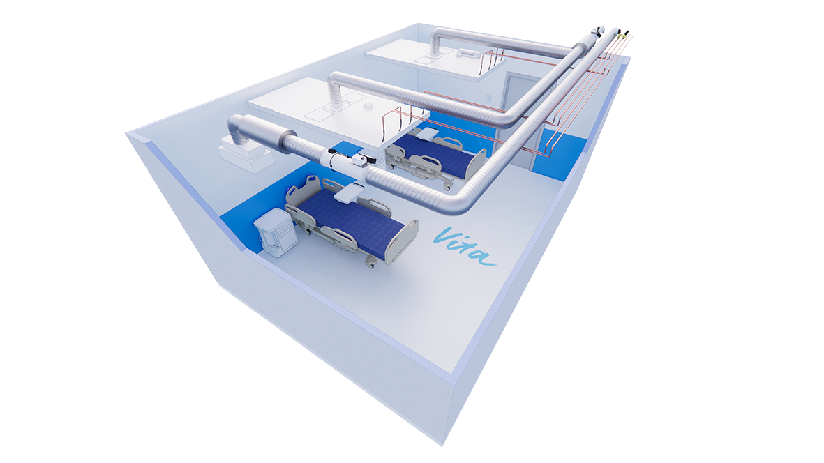
Two VPA room units controlled in parallel with a VRA controller in a two-patient room

VRA_TD_prod_example_4

Fig. 13. Two VPA room units controlled in parallel with a VRA controller in a two-patient room

Description

In this configuration, the Halton Vita Room Automation (VRA) controller controls two Halton Vita Patient Ava (VPA) room units in a two-patient room. The heating and cooling valves are located in the main pipes. The valve and valve actuator are not included in the basic delivery. The supply VAV damper is located in the main duct. The system also includes a VRA user panel, a window switch, and an exhaust VAV damper.

Design criteria

  • Two patient beds in one room
  • Heating and cooling valves located in the main pipes of the room
  • Supply air damper located in the main duct of the room
  • VPA room units have a common VRA controller
  • Exhaust airflow control with a motorised VAV damper (MOC/MUC)

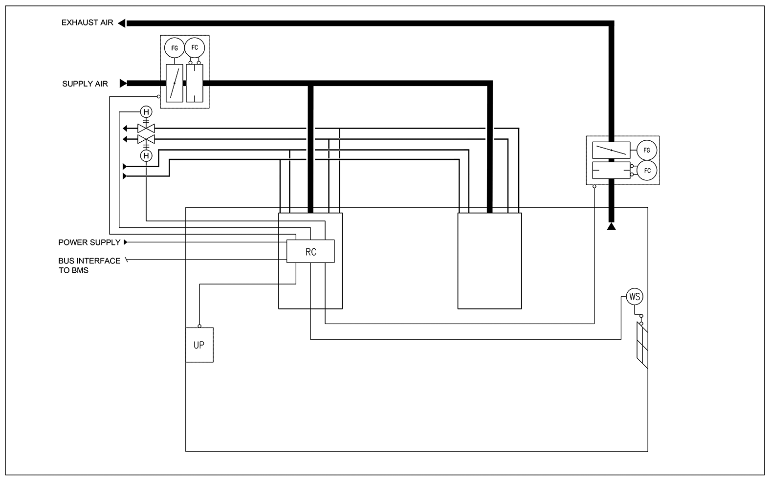
Schematic drawing

VRA_TD_prod_example_4_wiring

Fig. 14. Schematic drawing: Two VPA room units controlled in parallel with a VRA controller in a two-patient room

Equipment list

Code Equipment
UP VRA user panel
RC VRA controller unit
FG Airflow damper actuator
FC Airflow measurement
H Water valve actuator
WS Window switch

Order code examples for the system

  • 2 x VPA room unit with heating and cooling
    Code examples:
    1x VPA-3000-1200,NL=2,SP=Y,ND=Y,CV=NA,CT=D,VD=MO,SA=H1,CO=SA
    1x VPA-3000-1200,NL=2,SP=N,ND=Y,CV=NA,CT=D,VD=NA,SA=NA,CO=SA
  • 1 x VRA controller unit with VRA user panel and window switch
    Code example:
    VRA/VPA-PA-VR-VC,CP=C1,LC=NA,CV=L1,FS=DC,WS=W1,EL=NA,ZT=N
  • 1 x MOC VAV damper with sound attenuator for exhaust airflow
    Code example:
    MOC/G-200,MA=CS,CU=EM,FS=DS,SA=H1,RH=NA,ZT=N

Order code

VPA/L-W-NL; SP-ND-CV-CT-VD-SA-CO

S = Length (mm)
2400, 3000

W = Width (mm)
1200

NL = Number of loops
1       1 loop (cooling or heating)
2       2 loops (cooling and heating)

Other options and accessories

SP  = System package
N        No
Y        Yes

ND = With nozzle diffuser
Y        Yes

CV = Water valves and actuators
NA    Not assigned
L1     Linear, 0-10V

CT = Connection type
C       Plenum box with MSM
D       Plenum box without MSM

VD = With VAV damper
NA      Not assigned
MO     MOC + LMV-D3-MF-F.1 HI (EM)
MO1   MOC + GDB181.1E/3 (EH)
MU     MUC + GDB 161.1E (G2)

SA = Sound attenuator for VAV damper
NA      Not assigned
H1      L = 600 mm; Outlet = Inlet; Mineral wool
H2      L = 1000/1250 mm; Outlet = Inlet; Mineral wool
H3      L = 600 mm; Outlet = Inlet; Polyester fibre
H4      L = 1000/1250 mm; Outlet = Inlet; Polyester fibre

CO = Colour
SA       Signal white, antibacterial (RAL 9003)
SW     Signal white (RAL 9003)

Code example

VPA-3000-1200, SP=Y,NL=1,ND=Y,CV=L1,VD=NA,CT=NA,SA=NA,CO=SA

Downloads

  • Halton Vita Patient Ava (VPA) – Room unit

    Data

    en

    Shape 2
  • Halton Vita Patient Ava (VPA) – Huoneyksikkö

    Data

    fi

    Shape 2
  • Halton Vita Patient Ava (VPA) : module de chambre

    Data

    fr

    Shape 2
  • Halton Vita Patient Ava (VPA) – rumsenhet

    Data

    se

    Shape 2
  • VPA 辐射板

    Data

    cn

    Shape 2
Contact Us

"*" indicates required fields

Hidden
Marketing Communications Consent
Max. file size: 128 MB.
This field is for validation purposes and should be left unchanged.