Product / VRA
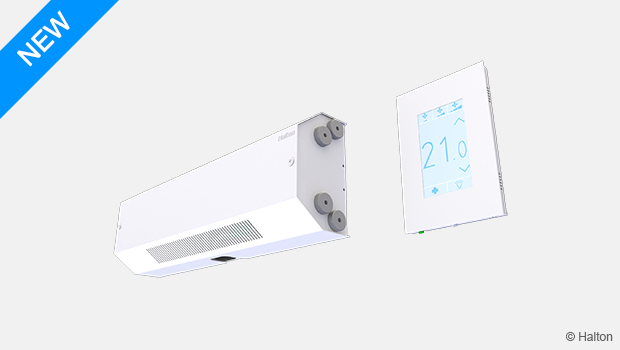
Halton Vita VRA – Room automation controller
Halton Vita VRA is a controller especially designed for controlling the automation system of a hospital patient room. It is always combined with other Halton products for the desired operation.
- Factory-tested controller and wiring, easy to install
- Pre-installed project-specific parameters, quick to commission
Overview
Halton Vita VRA is a controller especially designed for controlling the automation system of a hospital patient room. It is used for controlling the ventilation airflow, room temperature, and lighting in the room.
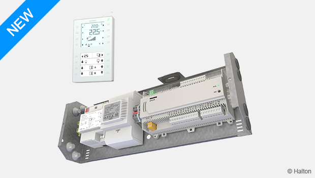
The Halton Vita VRA controller consists of a controller unit and a user panel. The Halton Vita VRA controller is always combined with other Halton products for the desired operation.
Application area
- Controlling the ventilation airflow, room temperature, and lighting in a hospital patient room.
Key features
- Factory-tested controller and wiring, easy to install
- Pre-installed project-specific parameters, quick to commission
- User panel with a glass surface, easy to use and keep clean
- Can be connected to the nurse call system of the hospital
Operating principle
The Halton Vita VRA controller controls Variable Air Volume (VAV) dampers, Halton Vita Patient Rex (VPR) chilled beams, and Halton Vita Patient Ava (VPA) radiant panels that are used for adjusting the ventilation airflow, room temperature, and lighting in a hospital patient room.
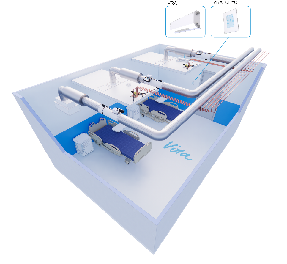
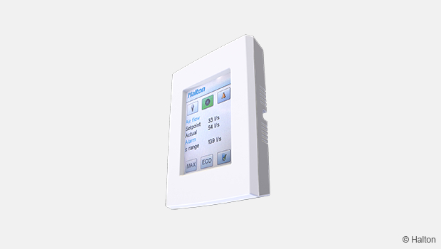
Fig.2. Overview of the Halton Vita VRA controller
The layout of a hospital patient room can vary in configuration from a one-bed room to a room with several beds. For example, each VPR chilled beam or VPA radiant panel can have its own dedicated Halton Vita VRA controller, or a single controller can be shared by the entire patient room. The controller set-up can be changed afterwards if needed.
Operating modes
The Halton Vita VRA controller has three operating modes for controlling the ventilation airflow in the room:
- Standby (min) for empty rooms – the Halton Vita VRA controller unit decreases the airflow rate compared to the airflow rate configured for the occupied (normal) operating mode. This operating mode is only used with VPA radiant panels.
- Occupied (normal) for rooms with one or more patients – the airflow rate is configured according to the number of patients in the room and the controller unit maintains the configured airflow rate.
- Boost (max) for situations where there are medical staff or other people in the room with the patient or patients – the controller unit increases the airflow rate.
Users can select the desired operating mode from the Halton Vita VRA user panel.
Airflow control
The Halton Vita VRA controller manages the room’s supply ventilation airflow rate as follows:
- With a VPA radiant panel, the controller manages a VAV damper, such as Halton Max Ultra Circular (MUC) or Halton Max One Circular (MOC).
- With a VPR chilled beam, the controller manages the Halton Air Quality (HAQ) control in the chilled beam.
The Halton Vita VRA controller manages the room’s exhaust ventilation airflow rate by controlling a VAV damper, such as Halton Max Ultra Circular (MUC) or Halton Max One Circular (MOC).
Temperature control
The room temperature sensor is located in the Halton Vita VRA user panel. The temperature is controlled using water valves for controlling the water flow rate. Cooling capacity can be enhanced by increasing the ventilation airflow.
Users can select the desired temperature level from the user panel.
Light control
The Halton Vita VRA controller uses Digital Addressable Lighting Interface (DALI) for controlling the lighting, that is, switching the lights on or off or dimming the lights.
An extra light button (accessory available separately) can be installed near a patient bed, for example. The light button is connected to the controller unit with a cable.
Condensation sensor
A condensation sensor is used to prevent condensation in chilled beams. It can be specified when selecting chilled beams. If the sensor detects condensation, the Halton Vita VRA controller closes the cooling valves.
Window switch
The window switch (accessory available separately) is a magnetic switch that is installed to the window and connected to the Halton Vita VRA controller unit with a cable. It detects whether the window is open or closed. If the window is open, the controller closes the cooling valves to prevent condensation.
System settings
The system setpoints and functions are controlled using either the Halton Vita VRA user panel or the Building Management System (BMS) via BACnet/IP or Modbus TCP/IP. Both control routes (user panel or BMS) are synchronised.
User levels
The Halton Vita VRA controller has three user levels for adjusting settings on the its user panel:
- Basic user
- Commissioning user
- Service user
Basic user
As a basic user, you can adjust some basic settings, such as the operating mode, room temperature, or lighting. No login is required.
Commissioning user
As a commissioning user, you can access settings that are configured in the commissioning phase.
Service user
As a service user, you can access the following:
- Settings that can be modified during the lifetime of the system
- Testing-related parameters
- Alarm information
Key technical data
| Feature | Description |
|---|---|
| Airflow rate control |
|
| Temperature control |
|
| Light control |
|
| Condensation sensor |
|
| Parameters |
|
| Communication |
|
| User interface |
|
| Optional functions |
|
Specification
A factory-tested and assembled room automation system. Includes control, measuring, and adjustment components.
- Easy-to-use user panel with a glass surface for controlling, commissioning, and testing the system
- Supply and exhaust ventilation airflow control
- Temperature control using valves
- Light control: on/off, with the dimming option
- BACnet/IP or Modbus TCP/IP communication
Electrical data
- Power supply 230 V AC
- Power consumption up to 84 W depending on additional components
- Power supplies L and N have their own fuses, type glass tube 4×20 4 A F
- Internal transformer 24 V AC
- 24 V AC terminal fuse, type glass tube 4×20 4 A F
Parameter settings
- Project-specific parameters pre-set at the factory
- Controller settings can be modified on site with a BACnet/IP or Modbus TCP/IP connection or manually from the user panel
Accessories
- Window switch
- Extra light button
- Mounting box
Design information
When designing a patient room, consider the following:
- If a patient room has several beds, should individual beds have their own control settings for airflow, or can the whole room be controlled as one area?
- Protected airflow can be created for medical staff or other people around individual beds by using dedicated airflow patterns.
- If the whole room is supposed to be controlled as one area, the airflow damper can be located in the main duct of the room.
- Is the exhaust airflow damper controlled by the Halton Vita VRA controller or some other system?
- If the exhaust airflow damper is controlled by the Halton Vita VRA controller, the supply and exhaust airflows can be balanced.
- Is a window switch needed?
- The window switch detects whether a window is open or closed. If the window is open, the cooling valve is closed to prevent condensation. The window switch is an accessory available separately.
- How are the lights in the patient room controlled? Is there a need for dimming the lights? Are the lights controlled in groups?
Installation information
The Halton Halton Vita VRA controller unit is usually installed to the main product (Halton Vita Patient Rex (VPR) chilled beam or Halton VPA radiant panel) at the factory. It is possible to remove the controller unit from the main product and install it separately, for example, in cases where all service should take place outside the room.
The Halton Vita VRA user panel must be installed in a place that is easily reachable, for example, next to a door.
Space requirements
The Halton Vita VRA controller unit is usually installed to the main product. Enough space must be reserved around the controller unit for service. If there is a solid ceiling, there must be a service hatch close to the controller unit.
Wiring
The wiring must only be carried out by qualified personnel following the local regulations.
For more information on wiring, see the project-specific wiring diagrams. In addition, you can find some example wiring diagrams in Technical reference data and a general system wiring diagram on the inside of the cover of the Halton Vita VRA controller unit.
Cabling requirements
- The wires connected to the terminals have a cross-sectional area of at least 0.5 mm2.
- Twisted-pair cables, shielding recommended.
- The minimum temperature rating of wire insulation is 85°C.
- The cables are halogen-free.
Connection diagram
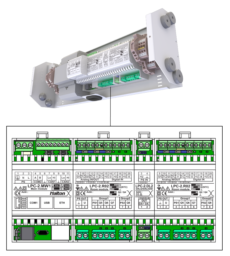
Fig.3. Connection diagram: Halton Vita VRA controller unit connections
Wiring schematics
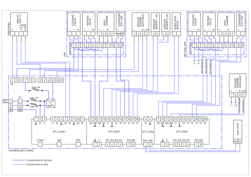
Fig 4. Wiring diagram for two individual Halton Vita Patient Rex (VPR) chilled beams, including DALI light control
Fig 5. Two individual Halton Vita Patient Ava radiant panels, including DALI light control
Terminals
| Terminal X1 | ||
| Terminal |
Name |
Comment |
| L |
L |
230 V AC Line |
| N |
N |
230 V AC Neutral |
| PE |
Ʇ |
Ground |
| Terminal X2 | ||
| Terminal | Name | Comment |
| 1 |
1 |
G, Terminals for supply voltage connection + (24V) |
| 2 |
2 |
G0, Terminals for supply voltage connection – (24V) |
| 3 |
3 |
G, Terminals for supply voltage connection + (24V) |
| 4 |
4 |
G0, Terminals for supply voltage connection – (24V) |
| 5 |
5 |
G, Terminals for supply voltage connection + (24V) |
| 6 |
6 |
G0, Terminals for supply voltage connection – (24V) |
| 7 |
7 |
G, Terminals for supply voltage connection + (24V) |
| 8 |
8 |
G0, Terminals for supply voltage connection – (24V) |
| 9 |
9 |
G, Terminals for supply voltage connection + (24V) |
| 10 |
10 |
G0, Terminals for supply voltage connection – (24V) |
| 11 |
11 |
G, Terminals for supply voltage connection + (24V) |
| 12 |
12 |
G0, Terminals for supply voltage connection – (24V) |
| Module: LPC-2.MW1 | ||
| Terminal |
Name |
Comment |
| 1 |
Ʇ |
Ground |
| 2 |
N |
230 V AC Neutral |
| 3 |
L |
230 V AC Line |
| 4 |
A |
Communication to display, line A |
| 5 |
B |
Communication to display, line B |
| Module: LPC-2.R02, primary | ||
| Terminal |
Name |
Comment |
| 1 |
Ʇ |
0 DC V power supply to user panel |
| 2 |
U |
+ 24 DC V power supply to user panel |
| 9 |
Q1 |
Heating valve control |
| 10 |
Q2 |
Cooling valve control |
| 11 |
Q3 |
Supply damper actuator control |
| 12 |
Q4 |
Exhaust damper actuator control |
| 13 |
I1 |
Supply damper pressure/airflow measurement |
| 14 |
I2 |
Exhaust damper pressure/airflow measurement |
| 15 |
+U |
Power supply to window switch |
| 16 |
I3 |
Window switch |
| 17 |
+U |
Power supply to condensation sensor |
| 18 |
I4 |
Condensation sensor |
| 19 |
+U |
Power supply to extra light button |
| 20 |
I5 |
Extra light button |
| Module: LPC-2.DL2 | ||
| Terminal |
Name |
Comment |
| 1 |
DA+ |
DALI, line + |
| 2 |
DA- |
DALI, line 1 |
| Module: LPC-2.R02, secondary | ||
| Terminal |
Name |
Comment |
| 9 |
Q1 |
Heating valve control |
| 10 |
Q2 |
Cooling valve control |
| 11 |
Q3 |
Supply damper actuator control |
| 12 |
Q4 |
Exhaust damper actuator control |
| 13 |
I1 |
Supply damper pressure/airflow measurement |
| 14 |
I2 |
Exhaust damper pressure/airflow measurement |
| 15 |
+U |
Power supply to window switch |
| 16 |
I3 |
Window switch |
| 17 |
+U |
Power supply to condensation sensor |
| 18 |
I4 |
Condensation sensor |
| 19 |
+U |
Power supply to extra light button |
| 20 |
I5 |
Extra light button |
Connection schemas
Connection schema: Halton Vita VRA user panel to Halton Vita VRA controller unit
|
Halton Vita VRA user panel |
Halton Vita VRA controller unit |
|||
| Terminal | Name | Terminal |
Name |
|
| GOT.111/COM1_A | COM1 A |
↔ |
LPC-2.MW1/COM2_A | COM2 A |
| GOT.111/COM1_B | COM1 B |
↔ |
LPC-2.MW1/COM2_B | COM2 B |
| GOT.111/PS1.1 | +24 V DC |
↔ |
LPC-2.R02/U | 2 |
| GOT.111/PS1.2 | 0 V DC |
↔ |
LPC-2.R02/Ʇ | 1 |
Connection schema: Halton Vita Patient Rex (VPR) junction box to parallel Halton Vita Patient Rex (VPR)
|
Halton Vita Patient Rex (VPR) junction box |
Parallel Halton Vita Patient Rex (VPR) | |||
| Terminal | Name | Terminal |
Name |
|
| Junction box/7 | +24 V |
↔ |
Parallel VPR/1 | 1 |
| Junction box/8 | 0 V |
↔ |
Parallel VPR/2 | 2 |
| Junction box/3 | 3 |
↔ |
Parallel VPR/3 | 3 |
| Junction box/6 | 6 |
↔ |
Parallel VPR/6 | 6 |
| Junction box/9 | 9 |
↔ |
Parallel VPR/9 | 9 |
| Junction box/12 | 12 |
↔ |
Parallel VPR/11 | 11 |
| LPC-2.R02/I4 | 18 |
↔ |
Parallel VPR/12 | 12 |
Connection schema: Secondary Halton Vita Patient Rex (VPR) chilled beam to Halton Vita VRA controller unit
|
Secondary VPR |
VRA controller unit | |||
| Terminal | Name | Terminal |
Name |
|
| Secondary VPR/1 | 1 |
↔ |
X2.5 | +24 V |
| Secondary VPR/2 | 2 |
↔ |
X2.6 | 0 V |
| Secondary VPR/3 | 3 |
↔ |
Secondary LPC-2.R02/Q1 | 9 |
| Secondary VPR/6 | 6 |
↔ |
Secondary LPC-2.R02/Q2 | 10 |
| Secondary VPR/9 | 9 |
↔ |
Secondary LPC-2.R02/Q3 | 11 |
| Secondary VPR/11 | 11 |
↔ |
Secondary LPC-2.R02/+U | 17 |
| Secondary VPR/12 | 12 |
↔ |
Secondary LPC-2.R02/I4 | 18 |
Connection schema: Window switch to Halton Vita VRA controller unit
|
Window switch |
VRA controller unit |
|||
|
Terminal |
Name |
Terminal |
Name |
|
| Window switch | 1 |
↔ |
LPC-2.R02/+U | 15 |
| Window switch | 2 |
↔ |
LPC-2.R02/I3 | 16 |
Connection schema: Extra light button to Halton Vita VRA controller unit
|
Extra light button |
VRA controller unit | |||
| Terminal | Name | Terminal |
Name |
|
| Light button | 1 |
↔ |
LPC-2.R02/+U | 19 |
| Light button | 2 |
↔ |
LPC-2.R02/I5 | 20 |
Commissioning
The Halton Vita VRA controller unit is installed to the main product (Halton Vita Patient Rex chilled beam or Halton Vita Patient Ava radiant panel) at the factory and configured. External wiring needs to be checked before the system start-up.
The controller addressing is pre-set at the factory. If addressing needs to be changed later, it can be done using a computer via a USB cable. All system parameters can be modified using the Halton Vita VRA user panel or using the BMS via the communication bus.
Product selection examples
One Halton Vita Patient Rex (VPR) chilled beam controlled individually with a Halton Vita VRA room automation controller in a one-patient room
Fig. 5. One Halton Vita Patient Rex chilled beam controlled individually with a Halton Vita VRA controller in a one-patient room
Description
In this configuration, the Halton Halton Vita VRA controller controls one VPR chilled beam. The VPR chilled beam has heating and cooling valves, a motorised Halton Air Quality (HAQ) control, and a condensation sensor. The system also includes a Halton Vita VRA user panel, window switch, and an exhaust VAV damper. One controller can individually control two VPR chilled beams, and there can be several controllers in a room.
Design criteria
- Room with one patient bed
- VPR chilled beam has heating and cooling valves
- VPR chilled beam has motorised HAQ control
- Condensation sensor included in the VPR chilled beam
- Exhaust airflow control
Schematic drawing
Fig. 6. One Halton Vita Patient Rex chilled beam with one Halton Vita VRA controller in a one-patient room
Equipment list
| Code | Equipment |
| UP | Halton Vita VRA user panel |
| RC | Halton Vita VRA controller unit |
| FG | Airflow damper actuator |
| FC | Airflow measurement |
| H | Water valve actuator |
| CS | Condensation sensor |
| WS | Window switch |
Order code examples for the system
- 1 x VPR chilled beam with heating and cooling valves, motorised HAQ control, and condensation sensor
- Code example: VPR/C-3000-2500-S2N,TC=H,CO=W,AQ=B,EX=N,QV=Y,ZT=N
- 1 x VRA controller unit with VRA user panel and window switch
- Code example:
VRA/VPR-PA-VR-VC,CP=C1,LC=NA,WS=W1,EL=NA,CV=L1,FS=DC,NC=NA,RT=NA,ZT=N
- Code example:
- 1 x MOC VAV damper with attenuator for exhaust airflow
Code example: MOC/G-200,MA=CS,CU=EM,FS=DS,SA=H1,RH=NA,ZT=N
Two Halton Vita Patient Rex (VPR) chilled beams controlled in parallel with a Halton Vita VRA room automation controller in a two-patient room
Fig. 7. Two Halton Vita Patient Rex chilled beams controlled in parallel with a Halton Vita VRA room automation controller in a two-patient room
Description
In this configuration, the Halton Vita VRA controller controls two VPR chilled beams in one room. The heating and cooling valves are located in the main pipes. The valve and valve actuator are not included in the basic delivery. Each VPR chilled beam has a motorised Halton Air Quality (HAQ) control and a condensation sensor. The system also includes a Halton Vita VRA user panel, window switch, and an exhaust VAV damper. One controller can control up to eight VPR chilled beams in parallel.
Design criteria
- Room with two patient beds
- Heating and cooling valves are located in the main pipes of the room
- VPR chilled beams have motorised (HAQ) controls
- Condensation sensors included in the chilled beams
- VPR chilled beams have a parallel Halton Vita VRA controller
- Exhaust airflow control
Schematic drawing
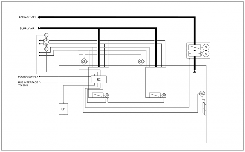
Fig. 8. Schematic drawing: Two Halton Vita Patient Rex chilled beams controlled in parallel with one Halton Vita VRA controller in a two-patient room
Equipment list
| Code | Equipment |
| UP | Halton Vita VRA user panel |
| RC | Halton Vita VRA controller unit |
| FG | Airflow damper actuator |
| FC | Airflow measurement |
| H | Water valve actuator |
| CS | Condensation sensor |
| WS | Window switch |
Order code examples for the system
- 2 x VPR chilled beam with heating and cooling coils, motorised HAQ control, and condensation sensor
- Code example:
VPR/C-3000-2500-S2N,TC=H,CO=W,AQ=B,EX=N,QV=Y,ZT=N
- Code example:
- 1 x VRA controller unit with VRA user panel and window switch
- Code example:
VRA/VPR-PA-VR-VC,CP=C1,LC=NA,WS=W1,EL=NA,CV=L1,FS=DC,NC=NA,RT=NA,ZT=N
- Code example:
- 1 x MOC VAV damper with attenuator for exhaust airflow
Code example: MOC/G-200,MA=CS,CU=EM,FS=DS,SA=H1,RH=NA,ZT=N
One Halton Vita Patient Ava (VPA) radiant panel controlled individually with a Halton Vita VRA room automation controller in a one-patient room
Fig. 9. One Halton Vita Patient Ava) radiant panel controlled individually with one (Halton Vita VRA) room automation controller in a one-patient room
Description
In this configuration, the Halton Vita VRA controller controls one VPA radiant panel. The VPA radiant panel has heating and cooling valves and a VAV damper. The system also includes a Halton Vita VRA user panel, a window switch, and an exhaust VAV damper. One controller can individually control two VPA radiant panels, and there can be several Halton Vita VRA controllers in a room.
Design criteria
- One patient bed in the room
- VPA radiant panel has heating and cooling valves
- VPA radiant panel has a motorised VAV damper
- VPA radiant panel has a parallel VRA controller
- Exhaust airflow control
Schematic drawing
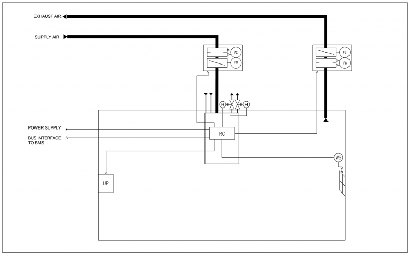
Fig. 10. Schematic drawing: One Halton Vita Patient Ava radiant panel controlled individually with one Halton Vita VRA controller in a one-patient room
Equipment list
| Code | Equipment |
| UP | Halton Vita VRA user panel |
| RC | Halton Vita VRA controller unit |
| FG | Airflow damper actuator |
| FC | Airflow measurement |
| H | Water valve actuator |
| WS | Window switch |
Order code examples for the system
- 1 x VPA radiant panel with heating and cooling valves, VAV damper, and condensation sensor
- Code example:
VPA-3000-1200,NL=2,ND=Y,CV=L1,VD=MO,CT=B,SA=H1,CO=SA,ZT=N
- Code example:
- 1 x VRA controller unit with VRA user panel and window switch
- Code example:
VRA/VPA-PA-VA-VC,CP=C1,LC=NA,WS=W1,EL=NA,CV=L1,FS=DC,NC=NA,RT=NA,ZT=N
- Code example:
- 1 x MOC VAV damper with attenuator for exhaust
Code example: MOC/G-200,MA=CS,CU=EM,FS=DS,SA=H1,RH=NA,ZT=N
Two Halton Vita Patient Ava (VPA) radiant panels controlled in parallel with a Halton Vita VRA controller in a two-patient room
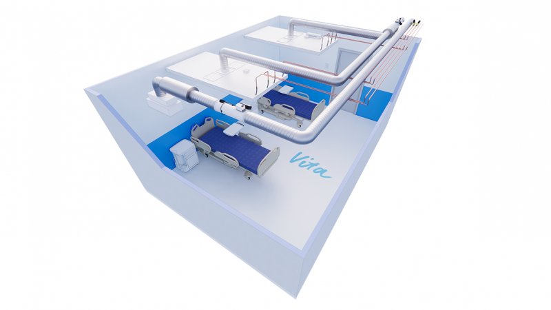
Fig. 11. Two Halton Vita Patient Ava radiant panels controlled in parallel with one Halton Vita VRA room automation controller in a two-patient room
Description
In this configuration, the Halton Vita VRA controller controls two VPA radiant panels in one room. The heating and cooling valves are located in the main pipes. The valve and valve actuator are not included in the basic delivery. The supply VAV damper is located in the main duct. The system also includes a Halton Vita VRA user panel, a window switch, and an exhaust VAV damper.
Design criteria
- Two patient beds in one room
- Heating and cooling valves located in the main pipes of the room
- Supply air damper located in the main duct of the room
- VPA radiant panels have a parallel VRA controller
- Exhaust airflow control
Schematic drawing
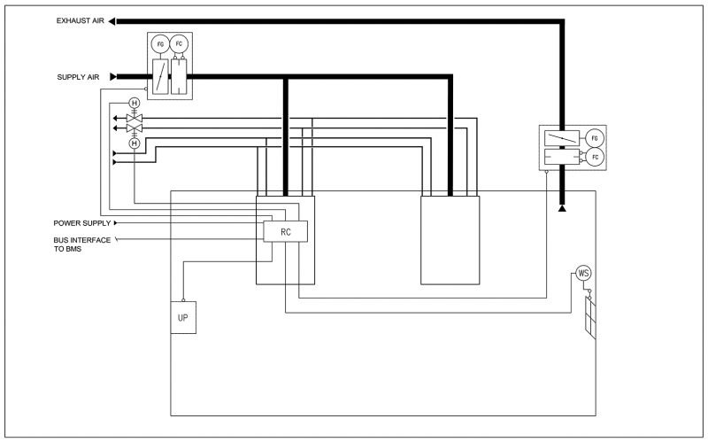
Fig. 12. Schematic drawing: Two Halton Vita patient Ava radiant panels controlled in parallel with one Halton Vita VRA controller in a two-patient room
Equipment list
| Code | Equipment |
| UP | Halton Vita VRA user panel |
| RC | Halton Vita VRA controller unit |
| FG | Airflow damper actuator |
| FC | Airflow measurement |
| H | Water valve actuator |
| WS | Window switch |
Order code examples for the system
- 2 x VPA radiant panel with heating and cooling coils
- Code example:
VPA-3000-1200,NL=2,ND=Y,CV=L1,VD=MO,CT=B,SA=H1,CO=SA,ZT=N
- Code example:
- 1 x VRA controller unit with VRA user panel and window switch
- Code example:
VRA/VPA-PA-VA-VC,CP=C1,LC=NA,WS=W1,EL=NA,CV=L1,FS=DC,NC=NA,RT=NA,ZT=N
- Code example:
- 1 x MOC VAV damper with attenuator for exhaust airflow
Code example: MOC/G-200,MA=CS,CU=EM,FS=DS,SA=H1,RH=NA,ZT=N
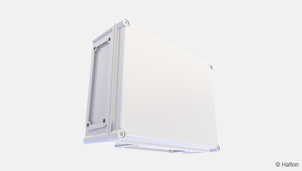
Structure and components
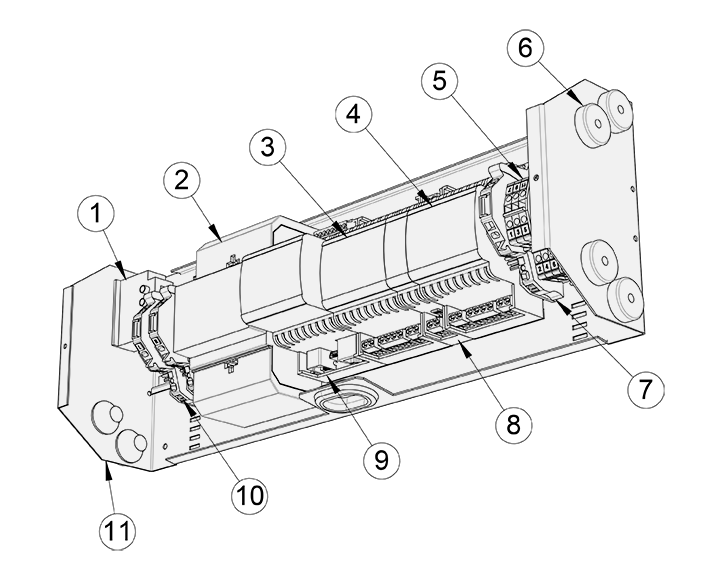
| No. | Part | Material |
| 1 | Power socket | Plug included |
| 2 | Transformer | 60 W |
| 3 | I/O unit | LPC-2.R02, primary |
| 4 | I/O unit | LPC-2.R02, secondary |
| 5 | 24 V AC terminals | Actuator/sensor power connection |
| 6 | Bushing TET | Bushing TET 7-10 |
| 7 | 24 V AC fuse | 4 A fast |
| 8 | DALI unit | LPC-2.DL2 |
| 9 | Main unit | LPC-2.MW1 |
| 10 | 230 V AC fuses | 4 A fast |
| 11 | Controller unit case | Casing and top cover painted galvanised steel |
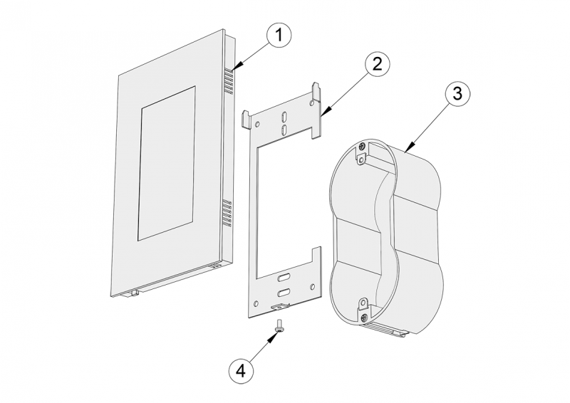
Fig. 14. Halton Vita VRA user panel components
| No. | Part | Details |
| 1 | User panel | Glass surface, touch screen |
| 2 | Mounting bracket | Metal |
| 3 | Mounting box (accessory available separately) | Double mounting box, options TEM HM40 or similar |
| 4 | Screw | M3 x 6 mm (hex AV10) |
Dimensions and weight
The dimensions are given in millimeters (mm).
Controller unit
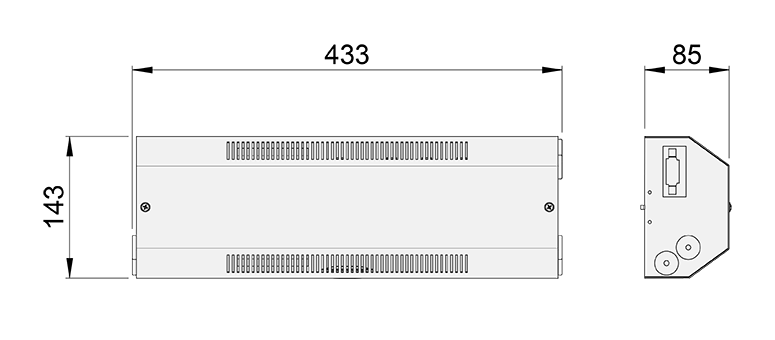
Fig 15. Halton Vita VRA controller unit dimensions
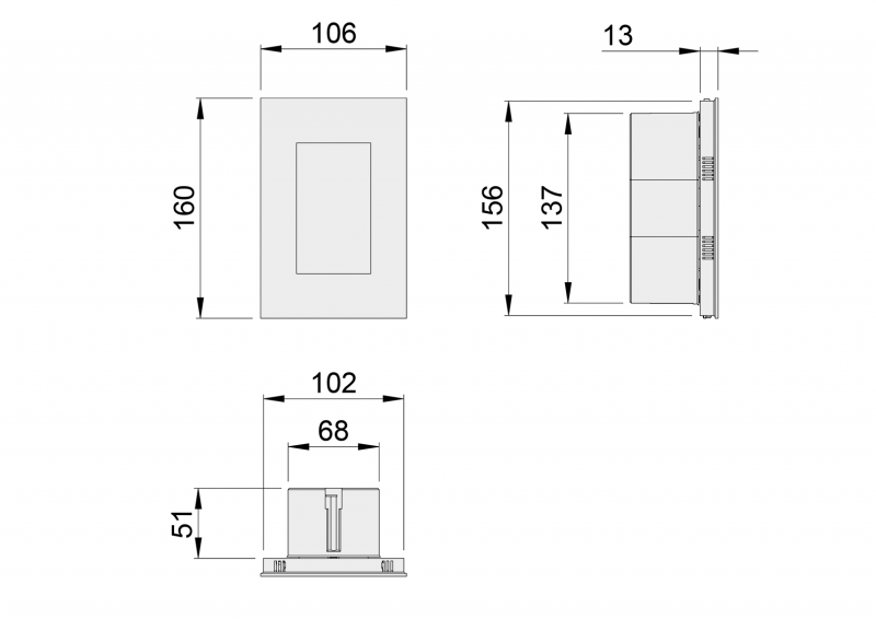 Fig 16. Halton Vita VRA user panel dimensions (user panel + mounting box)
Weight:
- Halton Vita VRA controller unit: 2.1 kg
- Halton Vita VRA user panel: 0.2 kg
Accessories
- Window sensor: SC570 – FSM
- Extra light button: Exxact WDE008204
Order code
VRA/P-C-S-E, CP-LC-CV-FS-WS-EL-ZT
P = Parent product
VPA VPA
VPR VPR
C = Controller type
PA One or several beams or panels on paraller
IN Two induvidual beams or panels
S = Supply air control mode
MA Manual
VR Motorised, step control (VPR)
VA Motorised, VAV control (VPA)
E = Exhaust air control mode
NA Not assigned
SC Motorised, step control
VC Motorised, VAV control
Other options and accessories
CP = Control panel
C1 4.3 inch touch panel
LC = Light controller mode
NA Not assigned
L1 Relay (on/off)
L2 DALI
CV = Water valves actuator control
NA Not assigned
DA4 AB-QM with ABNM 24V NC
FS = Factory-set airflow limits
DS Default factory setting
DC Customer specified setting
WS = Window sensor
NA Not assigned
W1 Window sensor
EL = Extra switch for light
NA Not assigned
E1 Extra switch for light
ZT = Tailored product
N No
Y Yes (ETO)
Code example
VRA/VPA-IN-VA-VC,CP=C1,LC=L2,CV=L1,FS=DS,NC=NA,RT=R1,ZT=N,WS=W1 AC=WS,EL
Downloads
"*" indicates required fields
Halton Vita HTP – Control panel
product
Halton Vita VRA – Room automation controller
product
Halton Vita VSP – Supervisory panel
product
Halton Workplace WRA – Room automation controller
product
Halton Workplace WSO – System optimiser central unit
product