Product / VSP
Halton Vita VSP – Supervisory panel
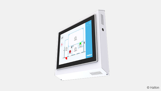
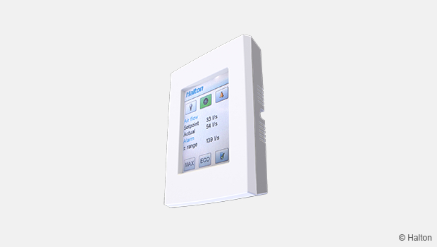
The Halton Vita VSP -supervisory panel displays the cleanroom conditions in two views: overall view and room view.
The supervisory panel is typically located at the main entrance of the cleanroom or in the personnel anteroom where users can easily see the conditions of the cleanroom to ensure safety when entering the cleanroom.
Overview
The Halton Vita VSP -supervisory panel displays the cleanroom conditions in two views: overall view and room view. The supervisory panel is typically located at the main entrance of the cleanroom or in the personnel anteroom where users can easily see the conditions of the cleanroom to ensure safety when entering the cleanroom. The service personnel can use the supervisory panel also for adjusting the cleanroom system.
The room controllers (VLR) are connected to the local supervisory panel via an Ethernet communication bus by using Modbus TCP/IP or BACnet/IP. The measurement values of the room, fume cupboards, and biosafety cabinets as well as the active alarms are displayed on the supervisory panel.
The essential setpoints and operation values of the room, fume cupboards and biosafety cabinets can be adjusted from the supervisory panel.
Fume cupboards and biosafety cabinets are connected to the room controller (VLR) using an RS-485 field bus.
The status information and all measurement values are connected to trend monitoring and they are arranged in groups by the space. The space layout drawing and the status information and measurement values of the related spaces are connected to the graphics on the supervisory panel. The layout is always customized to each project.
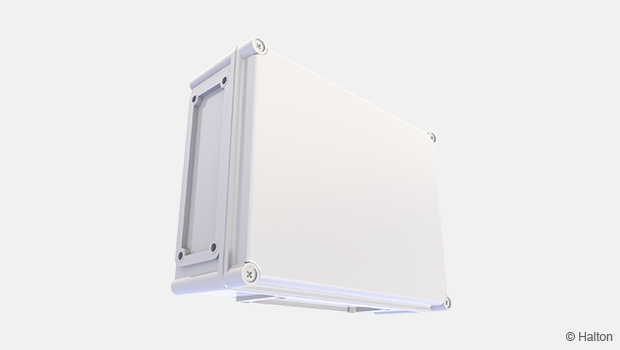
Structure and materials
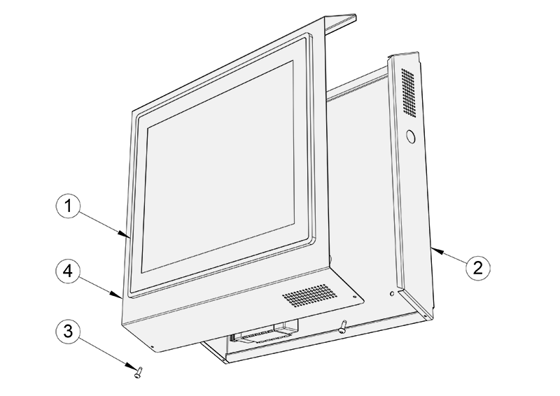
| No. | Part | Material |
| 1 | User panel | Class surface, touch screen |
| 2 | Control unit case, casing | Galvanised steel, polyester painted white (RAL 9003) |
| 3 | Screw | 2 pcs, 4,2X13 (TX20) |
| 4 | Control unit case, top cover | Galvanised steel, polyester painted white (RAL 9003) |
Dimensions and weight
Halton Vita VSP -supervisory panel dimensions. The dimensions are given in millimeters.
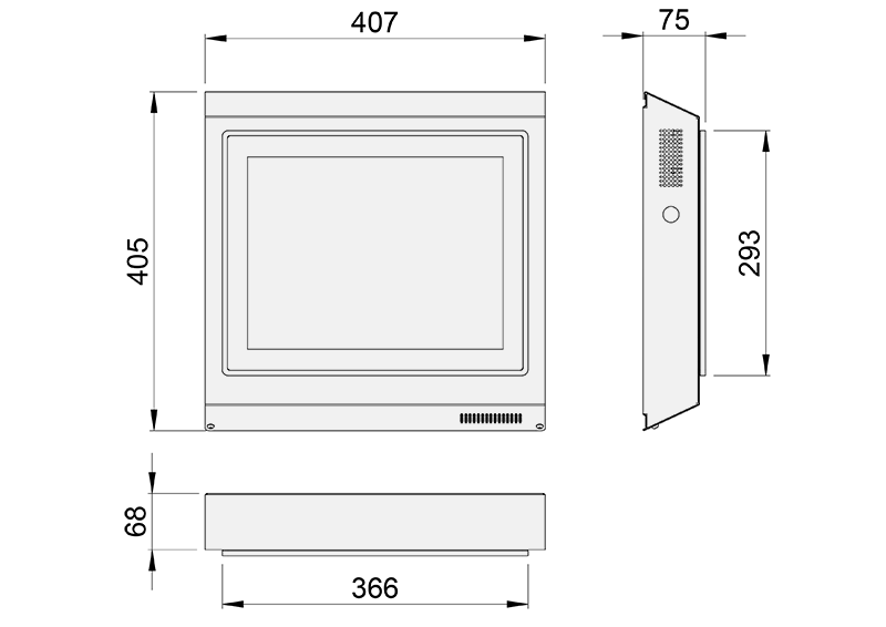
Fig.1. Supervisory panel dimensions (front view)
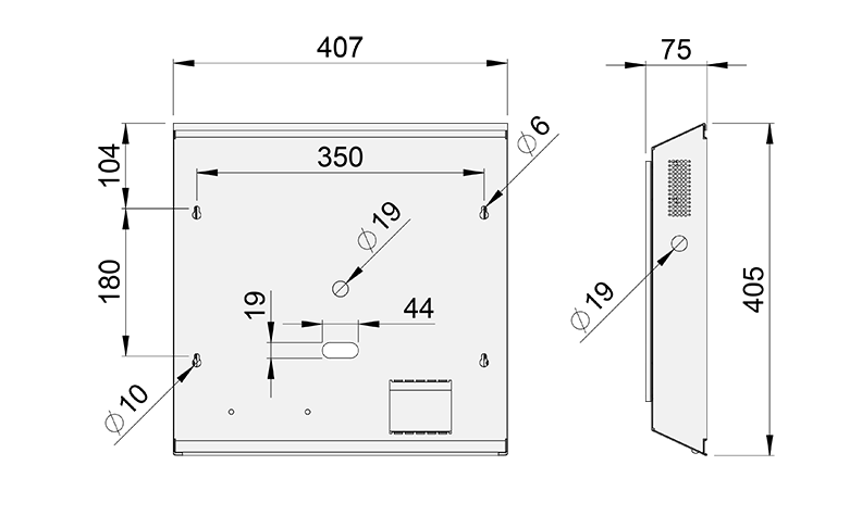
Fig.2. Supervisory panel dimensions (back view)
Weight:
- Control unit case: 1.2 kg
- User panel: 2.8 kg
Installation
Mount the frame to the wall with screws. Connect the communication cable (RJ45) and power supply to the connectors on the back of the control panel. Attach the display panel to the front panel and the front panel to the frame.
Note! There must be an electrical socket behind the frame for the transformer. In addition, the communication cable must be brought inside the frame.
Order code
VSP, ZT=N
M = Model
15 Display 15″
N = Number of rooms
S Standard
Other options and accessories
ZT = Tailored product
N No
Y Yes (ETO)
Code example
VSP/15-S
Downloads
"*" indicates required fields
Halton Vita HTP – Control panel
product
Halton Vita VRA – Room automation controller
product
Halton Vita VSP – Supervisory panel
product
Halton Workplace WRA – Room automation controller
product
Halton Workplace WSO – System optimiser central unit
product