Product / VPA
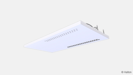
Halton Vita Patient Ava (VPA) – Room unit
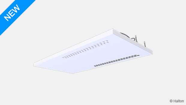
Halton Vita Patient Ava is a complete room unit with integrated radiant cooling and heating combined with a unique protective airflow pattern. The room unit provides comfortable indoor climate conditions for patients and a safe working environment for medical staff.
Halton Vita Patient Ava is part of the Halton Vita Patient solutions offering.
- Low and smooth design with hygienic, easily cleanable surfaces.
- Automation system with an easy-to-use interface available to ensure flexibility and optimal function in
different operating modes.
Overview
Halton Vita Patient Ava is a complete room unit with integrated radiant cooling and heating combined with a unique protective airflow pattern. The room unit provides comfortable indoor climate conditions for patients and a safe working environment for medical staff. Halton Vita Patient Ava is part of the Halton Vita Patient solutions offering.
Applications
- Hospital patient rooms
Key features
- Radiant cooling and heating with supply air distribution for comfortable and optimal indoor climate conditions.
- Protective airflow pattern to enable a safe environment for patients and medical staff.
- Low and smooth design with hygienic, easily cleanable surfaces.
- Suitable for both ceiling-integrated and exposed ceiling installation.
- A complete solution with operating mode control for patient rooms.
- Automation system with an easy-to-use interface available to ensure flexibility and optimal function in
different operating modes.
Operating principle
The Halton Vita Patient Ava room unit combines supply air distribution with a radiant panel and automation, which makes it a complete solution for patient rooms.
The radiant panel is used for ensuring individual thermal comfort. The cool or heat is transferred from the water flowing through the radiant panel’s copper pipe to the aluminium sheet that works as a radiant surface to the surrounding space.
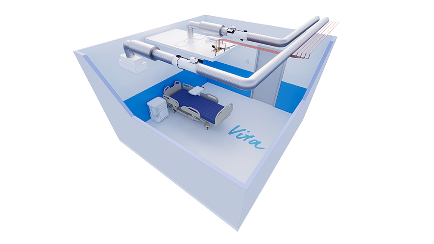
Protective airflow pattern
To reduce the risk of infections and enhance the protection of medical staff, the Halton Vita Patient Ava room unit provides a unique protective airflow pattern. The solution protects the medical staff by generating a barrier from the supply air, at the same time maintaining thermal comfort for the patient.
When equipped with the Halton Vita Room Automation system and a VAV airflow damper, the Halton Vita Patient Ava room unit has three different operating modes:
- Standby (min) for empty rooms – the Halton Vita Room Automation controller decreases the airflow rate compared to the airflow rate configured for the occupied (normal) operating mode.
- Occupied (normal) for rooms with one or more patients – the airflow rate is configured according to the number of patients in the room and the Halton Vita Room Automation controller maintains the configured airflow rate.
- Boost (max) for situations where there are medical staff or other people in the room with the patient or patients – the Halton Vita Room Automation controller increases the airflow rate.
With the boost operating mode, the supply airflow is designed to generate a protective airflow pattern that prevents bacteria exhaled by the patient from entering the breathing zone of medical staff. At the same time, fresh, clean air is brought to the breathing zone of medical staff.
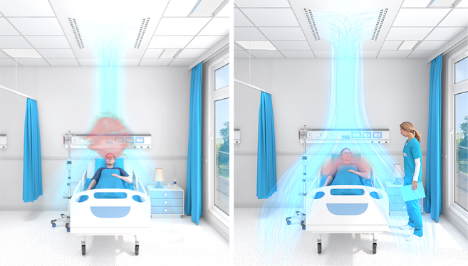
Fig. 2. Protective airflow pattern. Left: Normal mode. Right: Boost mode with protective airflow pattern.
Thermal comfort
The Halton Vita Room Automation system can be designed so that it enables individual control for each patient separately, which makes it possible for patients to control the temperature level according to their individual needs.
The temperature level is controlled by adjusting the flow rate and temperature of the water circulating in the copper pipes. As a result, the thermal comfort of the patient is optimised. If necessary, the cooling capacity can be enhanced by increasing the airflow rate.
Cooling and heating capacity
The cooling capacity of radiant panels is measured according to EN 14240. The installation type (ceiling-integrated or exposed ceiling installation) affects the output performance. Therefore, in the Halton HIT Design software, where the cooling and heating capacity can be checked for each case, the installation type should be selected to get more specific output data.
The heating capacity of radiant panels is measured according to EN 14037:2016. The heating capacity of Halton radiant panels has been measured in an accredited third-party laboratory to fulfil the requirements of EN 14037-2.
Key technical data
| Feature | Description |
| Airflow rate | 10…70 l/s |
| Dimensions | 2400×1200 mm or 3000×1200 mm |
| Duct connection | ø 160 mm |
| Cooling capacity | Up to 785 W (Tr 24°C, Ts 18°C, qvair 70 l/s, Tw 15°C, qmwater 0.035 kg/s) |
| Heating capacity | Up to 605 W (Tr 20°C, Ts 20°C, Tw 50°C, qmwater 0.030 kg/s) |
| Weight | 36.8…67.1 kg (excl. water) |
Features and options
| Category | Feature | Options |
| Size | Length |
|
| Width | Nominal width 1200 mm | |
| Cooling and heating |
Number of loops |
|
| Water valves and actuators |
|
|
| Automation | System package |
|
| Airflow | Nozzle diffuser | Always included |
| Connection type |
|
|
| VAV damper |
For information on the actuator options of these VAV |
|
| Finishing | Colour | White antibacterial epoxy polyester powder paint (RAL 9003/20%). Standard white as option. |
| Accessories | Sound attenuator | With or without sound attenuation. For information on the options, see Order code. |
For information on the order code, see Order code.
Halton Vita Patient Ava product models
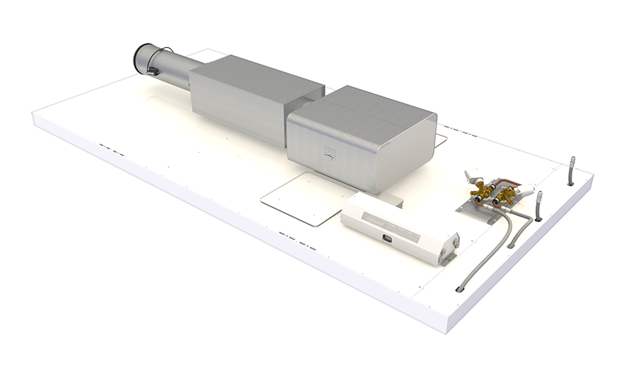
Fig. 3. Halton Vita Patient Ava room unit with automation (a radiant panel equipped with a Halton Vita Room Automation controller unit, a VAV damper, a sound attenuator, a plenum box, and water valves and actuators)
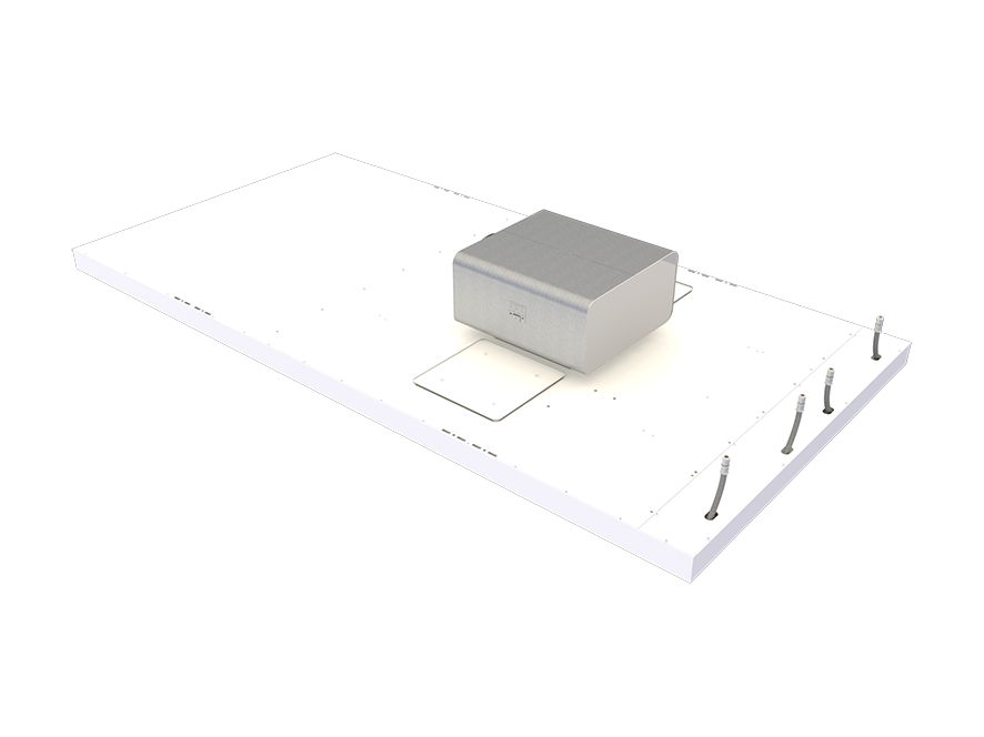
Fig. 4. Halton Vita Patient Ava room unit without automation (a radiant panel equipped with a plenum box including a manual airflow damper)
System package
The system package should be selected in the Halton Vita Patient Ava (VPA) product order code when the product is intended to be equipped with Halton Vita VRA room automation system.
The package consists of a controller unit and a user panel used to adjust the ventilation airflow, room temperature, and lighting in a hospital patient room.
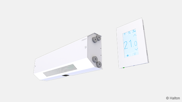
Fig 5. Automation control unit and a user panel
The controller unit is installed on top of the panel and the user panel on the wall.
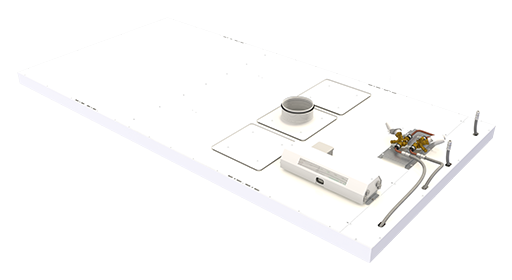
Fig 6. Location of system package components
You can find more detailed information about the system package under Halton Vita VRA room automation product pages.
Specification
- A room unit designed for hospital patient rooms.
- Combines radiant cooling and heating with supply air distribution.
- The room unit is equipped with an automation system that enables three different operating modes, airflow control, as well as the temperature and lighting control of the patient room.
- The pre-programmed and pre-tested automation system includes a hygienic user panel for adjusting the operating mode, room temperature, and lighting of the room.
- With the automation system and a VAV airflow damper, the room unit increases the airflow rate and provides an airflow pattern that protects the medical staff from bacteria exhaled by the patient.
Structure
- Unit length 2400 or 3000 mm.
- Unit width 1200 mm, thickness 75 mm.
- Inlet duct diameter 160 mm.
- Pipework’s maximum operating pressure 1.0 MPa.
- There are two inspection hatches to enable cleaning the air chamber of the unit.
Materials
- Front panel manufactured from aluminium.
- Duct connection and related parts manufactured from galvanised steel.
- All visible parts painted. White antibacterial epoxy polyester powder paint (RAL 9003/20%).
- All pipes manufactured from copper.
- All pipe joints soldered.
- All pipe joints pressure-tested at the factory.
Packaging and identification
- The visible surface of the product is protected by a removable plastic coating.
- The duct connection and pipe ends remain sealed during transport.
- The product is packed on a pallet.
- The product is identified by a serial number printed on labels attached both to the product and the package.
Design information
When designing a patient room, consider the following:
- To ensure the protective airflow pattern, the Halton Vita Patient Ava room unit should be installed above each patient bed in a patient room.
- Are both cooling and heating functions needed?
- The room unit can be equipped with one or two water loops. Typically, loop 1 is used for cooling and loop 2 for heating.
- To enable individual temperature control for patients, it is recommended that the room unit is equipped with two water loops (cooling and heating) and Halton Vita Room Automation.
- If a patient room has several beds, it is recommended that the airflow and temperature can be individually adjusted for each patient. This enables the protective airflow pattern for medical staff or other people around individual beds.
- If needed, it is possible to control the whole room as one area. In this case, the airflow dampers are located in the main ducts of the room, not in the room unit branches.
- Is it possible to open the windows in the room?
- If it is possible to open the windows in the room, it is recommended that window switches are used. A window switch detects whether a window is open or closed. If the window is open, the cooling valve is closed to prevent condensation. The window switch is an accessory available separately and needs to be specified in the design documents.
- How are the lights in the patient room controlled?
- The Halton Vita Room Automation controller uses Digital Addressable Lighting Interface (DALI) for controlling the lighting: switching the lights on or off, dimming the lights, or controlling the lights in groups.
Installation
Halton Vita Patient Ava room units are suitable for ceiling-integrated and exposed ceiling installation.
To ensure the protective airflow pattern, the Halton Vita Patient Ava room unit should be installed above each patient bed in a patient room. The end with the water connections should come above the head end of the patient bed. The distance between the end wall and the unit should be 600 mm.
The required free height from the lowest point of the front panel to the ceiling is 341 mm.
Enough space must be reserved around the unit for maintenance. If there is a solid ceiling, there must be a service hatch close to the unit, to enable access to the top of the unit.
The unit is installed by suspending it from the ceiling using wires and snap hooks.
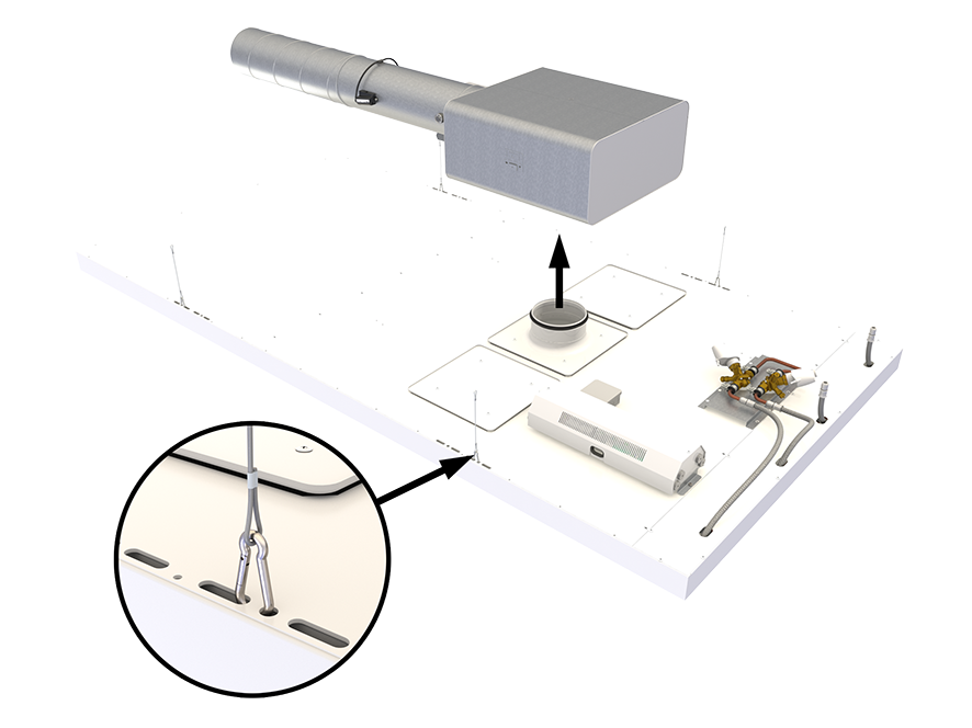
Fig. 7. Halton Vita Patient Ava installation
NOTE: Wires, snap hooks and flexible hoses are not included in the delivery.
Commissioning
Airflow adjustment
To enable the protective airflow pattern, the nozzles are directed towards the longitudinal centre line of the room unit. If necessary, the direction of the nozzles can be adjusted.
Cooling
The recommended cooling water mass flow rate is 0.020…0.035 kg/s, resulting in a temperature rise of 1…3°C in the radiant panel. To avoid condensation, the recommended temperature of the inlet water is over the dew point temperature of the room.
Heating
The recommended heating water mass flow rate is 0.015…0.030 kg/s, resulting in a temperature drop of 3…10°C in the radiant panel. In typical rooms (room height up to 3 m), the usual recommended maximum temperature of the inlet water is 50°C due to a risk of the radiation asymmetry being too high.
Structure and materials
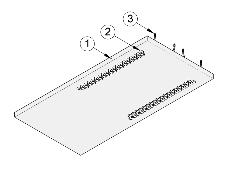
Fig. 8. Structure of Halton Vita Patient Ava room unit, bottom view
| No. | Part | Description | Note |
| 1 | Front panel | Pre-painted aluminium. White antibacterial epoxy polyester powder paint (RAL 9003/20%). Standard white as option. | – |
| 2 | Air nozzles | Plastic (polyacetal) | – |
| 3 | Radiant panel connection pipes |
Connection pipes with push-fit fittings: stainless steel, ø 10 mm | – |
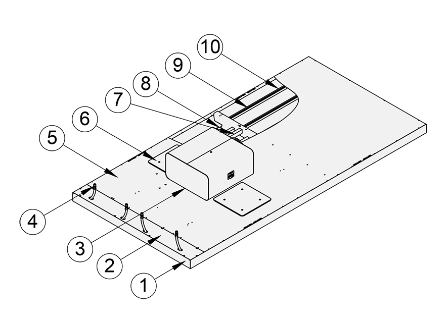
Fig. 9. Structure of Halton Vita Patient Ava room unit, top view
| No. | Part | Description | Note |
| 1 | Front panel | Pre-painted aluminium. White antibacterial epoxy polyester powder paint (RAL 9003/20%). Standard white as option. | – |
| 2 | Cover plate | Aluminium | – |
| 3 | Plenum box | Galvanised steel, duct connection: ø 160 mm | – |
| 4 | Radiant panel connection pipes |
Connection pipes with push-fit fittings: stainless steel, ø 10 mm | – |
| 5 | Top cover plate | Aluminium | – |
| 6 | Inspection hatches | Galvanised steel | – |
| 7 | Sound absorption material |
Polyester fibre | – |
| 8 | Air nozzles | Plastic (polyacetal) | – |
| 9 | Radiant panel pipes |
Copper, ø 10 mm | – |
| 10 | Pipe fixing profiles | Aluminium |
Dimensions and weight
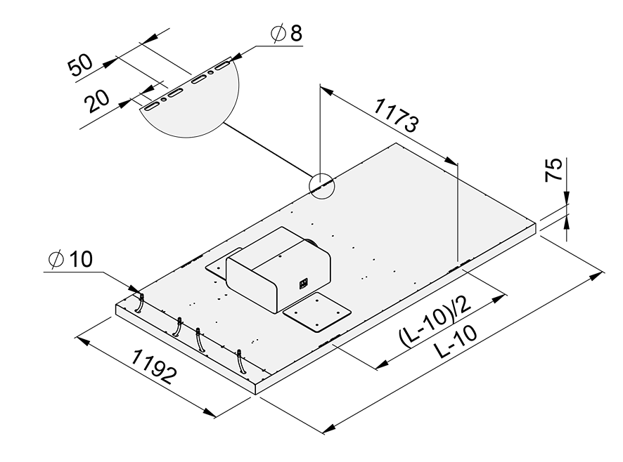
Fig. 10. Dimensions of Halton Vita Patient Ava room unit. L = 2400 or 3000 mm.

Fig. 11. Dimensions of Halton Vita Patient Ava room unit, side view.
Weight
| Unit length [mm] | Number of water loops |
Panel without automation, dry mass [kg] |
Panel with automation, dry mass [kg] |
Water mass [kg] |
| 2400 | 1 | 36.8 | 55 | 4.6 |
| 2400 | 2 | 40.7 | 59.9 | 6.7 |
| 3000 | 1 | 43.1 | 61.3 | 5.7 |
| 3000 | 2 | 47.9 | 67.1 | 8.4 |
Servicing
The front panel and other visible painted plates can be wiped using a damp cloth. The unit tolerates room disinfection with hydrogen peroxide.
There are two inspection hatches to enable cleaning the air chamber of the unit.
If installed exposed, it is recommended that the top of the unit is vacuumed.
For cleaning frequency, follow the maintenance schedule of the building.
Product selection examples
One VPA room unit controlled individually with a VRA controller in a one-patient
room
Description
In this configuration, the Halton Vita Room Automation (VRA) controller controls one Halton Vita Patient Ava (VPA) room unit. The VPA room unit has heating and cooling valves and a VAV damper. The system also includes a VRA user panel, a window switch, and an exhaust VAV damper. One VRA controller can individually control two VPA room units, and there can be several VRA controllers in a room.
Design criteria
- One patient bed in the room
- VPA room unit has heating and cooling valves
- VPA room unit has a motorised VAV damper (MOC/MUC)
- VPA room unit has an individual VRA controller
- Exhaust airflow control with a motorised VAV damper (MOC/MUC)
Schematic drawing
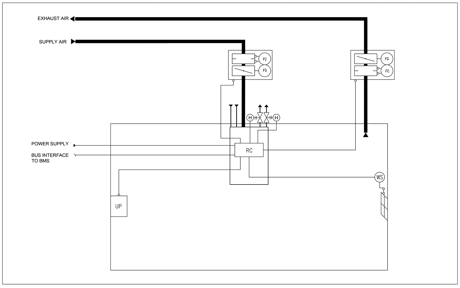
Fig. 12. Schematic drawing: One VPA room unit controlled individually with a VRA controller in a one-patient room
| Code | Equipment |
| UP | VRA user panel |
| RC | VRA controller unit |
| FG | Airflow damper actuator |
| FC | Airflow measurement |
| H | Water valve actuator |
| WS | Window switch |
Order code examples for the system
- 1 x VPA room unit with heating and cooling valves, VAV damper, and condensation sensor
Code example:
VPA-3000-1200,NL=2,SP=Y,ND=Y,CV=L1,CT=D,VD=MO,SA=H1,CO=SA - 1 x VRA controller unit with VRA user panel and window switch
Code example:
VRA/VPA-PA-VR-VC,CP=C1,LC=NA,CV=L1,FS=DC, WS=W1,EL=NA,ZT=N - 1 x MOC VAV damper with sound attenuator for exhaust
Code example:
MOC/G-160,MA=CS,CU=EM,FS=DS,SA=H1,RH=NA,ZT=N
Two VPA room units controlled in parallel with a VRA controller in a two-patient room
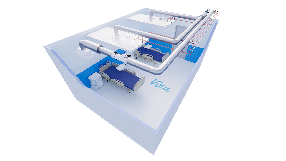
Fig. 13. Two VPA room units controlled in parallel with a VRA controller in a two-patient room
Description
In this configuration, the Halton Vita Room Automation (VRA) controller controls two Halton Vita Patient Ava (VPA) room units in a two-patient room. The heating and cooling valves are located in the main pipes. The valve and valve actuator are not included in the basic delivery. The supply VAV damper is located in the main duct. The system also includes a VRA user panel, a window switch, and an exhaust VAV damper.
Design criteria
- Two patient beds in one room
- Heating and cooling valves located in the main pipes of the room
- Supply air damper located in the main duct of the room
- VPA room units have a common VRA controller
- Exhaust airflow control with a motorised VAV damper (MOC/MUC)
Schematic drawing
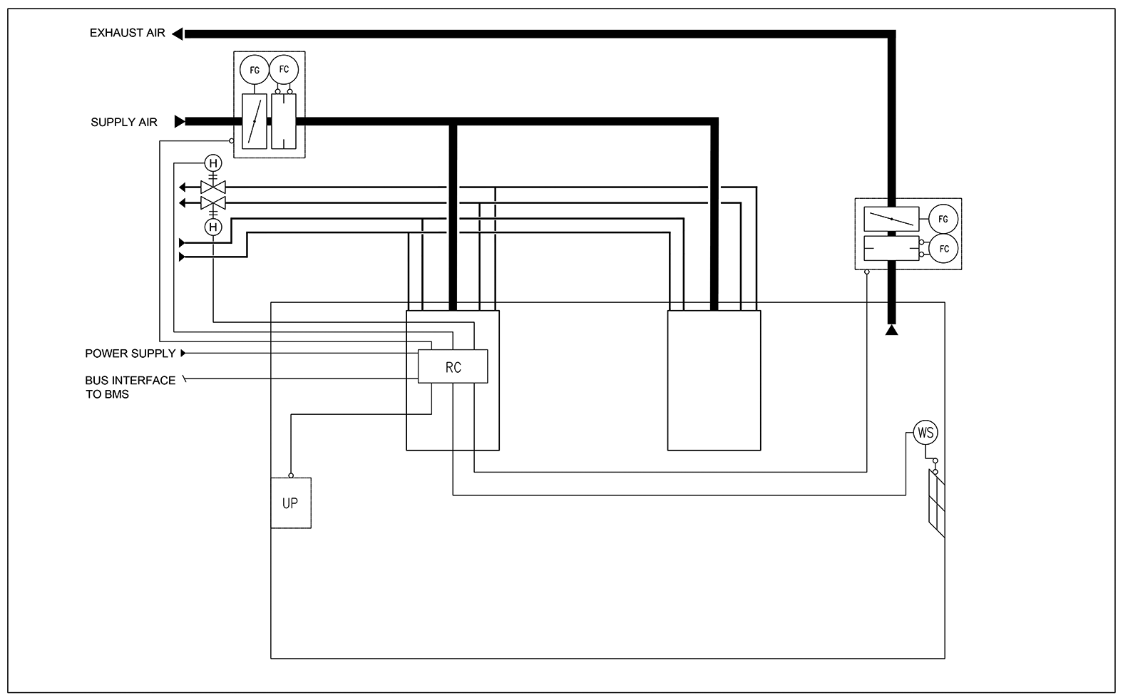
Fig. 14. Schematic drawing: Two VPA room units controlled in parallel with a VRA controller in a two-patient room
Equipment list
| Code | Equipment |
| UP | VRA user panel |
| RC | VRA controller unit |
| FG | Airflow damper actuator |
| FC | Airflow measurement |
| H | Water valve actuator |
| WS | Window switch |
Order code examples for the system
- 2 x VPA room unit with heating and cooling
Code examples:
1x VPA-3000-1200,NL=2,SP=Y,ND=Y,CV=NA,CT=D,VD=MO,SA=H1,CO=SA
1x VPA-3000-1200,NL=2,SP=N,ND=Y,CV=NA,CT=D,VD=NA,SA=NA,CO=SA - 1 x VRA controller unit with VRA user panel and window switch
Code example:
VRA/VPA-PA-VR-VC,CP=C1,LC=NA,CV=L1,FS=DC,WS=W1,EL=NA,ZT=N - 1 x MOC VAV damper with sound attenuator for exhaust airflow
Code example:
MOC/G-200,MA=CS,CU=EM,FS=DS,SA=H1,RH=NA,ZT=N
Order code
VPA-L-W-NL; SP-ND-CV-CT-VD-SA-CO
| Main options | |
| L = Length [mm] | 2400, 3000 |
| W = Width [mm] | 1200 |
| NL = Number of loops | |
| 1 | 1 loop (cooling or heating) |
| 2 | 2 loops (cooling and heating) |
| Other options and accessories | |
| SP = System package | |
| N | No |
| Y | Yes |
| ND = With nozzle diffuser | |
| Y | Yes |
| CV = Water valves and actuators | |
| NA | Not assigned |
| L1 | Linear, 0-10V |
| CT = Connection type | |
| C | Plenum box with MSM |
| D | Plenum box without MSM |
| VD = With VAV damper | |
| NA | Not assigned |
| MO | MOC + LMV-D3-MF-F.1 HI (EM) |
| MO1 | MOC + GDB181.1E/3 (EH) |
| MU | MUC + GDB 161.1E (G2) |
| SA = Sound attenuator for VAV damper | |
| NA | Not assigned |
| H1 | L = 600 mm; Outlet = Inlet; Mineral wool |
| H2 | L = 1000/1250 mm; Outlet = Inlet; Mineral wool |
| H3 | L = 600 mm; Outlet = Inlet; Polyester fibre |
| H4 | L = 1000/1250 mm; Outlet = Inlet; Polyester fibre |
| CO = Colour | |
| SA | Signal white, antibacterial (RAL 9003) |
| SW | Signal white (RAL 9003) |
Order code example
VPA-3000-1200; SP=Y,NL=1,ND=Y,CV=L1,VD=NA,CT=NA,SA=NA,CO=SA
Downloads
"*" indicates required fields