Product / BRD
BRD泄压风闸
浩盾 BRD 泄压阀广泛应用于钻井平台和船舶中防止通风管道系统中气压回流。


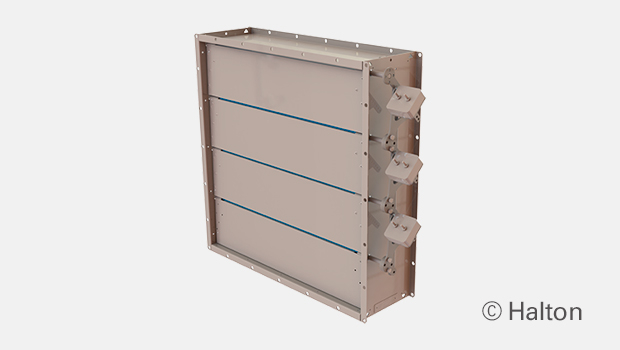
概述
- 焊连的外框可选材质为喷漆、镀锌或不锈钢。风叶为镀锌或不锈钢。
- 适合水平和垂直安装的型号
- 风叶包含硅胶密封,防止泄漏
- 通过ATEX/IECEx认证
- 闭合的阀防泄漏等级符合 EN 1751 2 级。测试尺寸为 1000×1000 mm。
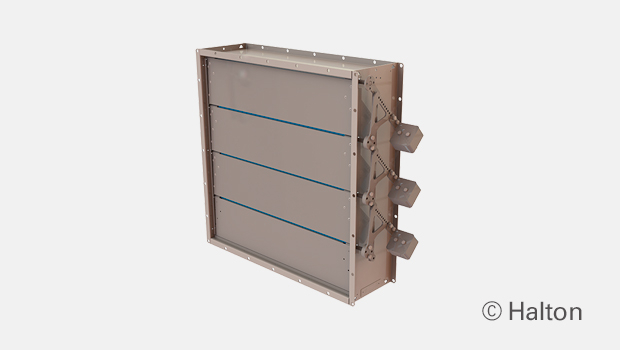
- 每片风叶相互连接且同时开闭
- 可通过改变重锤的位置调节开启压力
- 开启压力范围为 30 Pa 到 150 Pa(至多可选配 300 Pa)
- 重锤标配
- 重锤标配在右侧,也可选配左侧的重锤
- 调试时可对重锤进行最终调节
- 阀门结构可适应的最大管道压力为 5000 Pa,最大空气流速为 15 m/s。如果管道压力过高,请联系浩盾船舶寻求最佳解决方案。
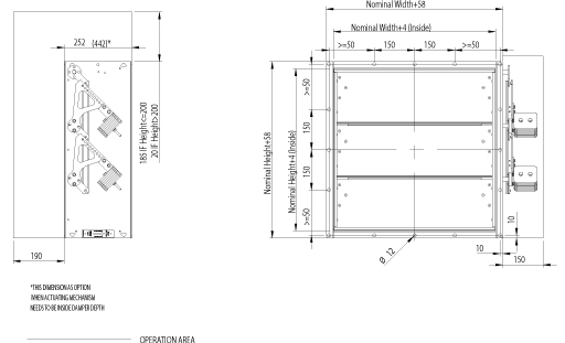
尺寸和材料厚度
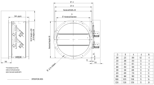
BRD 泄压阀符合国际标准,适用于矩形管道(宽度 B 150-1200 mm,高度 H 150-1400 mm,1 mm 间距)和圆形管道(直径 100 – 1250 mm)。可根据要求提供非标准尺寸。标准法兰宽度为 27 毫米。也可根据 ISO 15138 标准提供法兰和钻孔。模块化结构尺寸最大可达 2400x2800mm。标准框架材料厚度为 3 毫米。叶片由两片薄板组成,每片厚 0.8 毫米(三明治设计)。
BRD, 总图
圆形管道连接
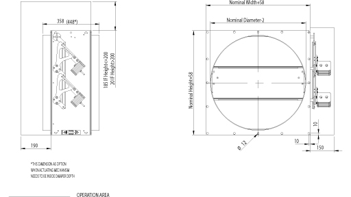
BRD 圆形,带连接法兰
材料和表面处理
| 部件 | 材料 | 表面处理 |
| 外框 | 碳钢 | 喷涂或镀锌 |
| 外框 | 不锈钢 EN 1.4301 (AISI304), EN 1.4404 (AISI316L), EN 1.4432 (AISI316L) | – |
| 叶片 | 铁 | 镀锌 |
| 叶片 | 不锈钢 EN 1.4301 (AISI304), EN 1.4404 (AISI316L), EN 1.4432 (AISI316L) | – |
| 免维护轴承 | 不锈钢 EN 1.4404 (AISI316L) / 可选项:青铜轴承 | – |
| 轴 | 不锈钢 EN 1.4404 (AISI316L) | – |
标准框架材料厚度为3mm。
叶片由两片0.8毫米厚的板材制成。
产品型号和附件
- 可提供水平和垂直安装型号。
- 可提供圆形连接件。
- 标准结构将配种放在右侧。左侧配重为可选项。
操作原理
泄压阀可在管道系统中实现单向泄压。该功能基于不平衡叶片。当管道中的压力上升超过选定值(从 30 Pa 到 150 Pa,最高可选 300 Pa)时,风阀叶片打开,以实现泄压。如需更高的开启压力,请联系浩盾海运。最小开启力可以通过配进行调节。当管道系统中的压力低于所需的最小开启力时,风阀叶片关闭并密封管道。
重量
标准浩盾BRD泄压阀的重量(kg)。框架厚度为3毫米。
| H/HEIGHT
(mm) |
B / WIDTH (mm) | |||||||||||
| 150 | 200 | 300 | 400 | 500 | 600 | 700 | 800 | 900 | 1000 | 1100 | 1200 | |
| 150 | 8 | 9 | 11 | 13 | 15 | 16 | 18 | 20 | 22 | 24 | 25 | 27 |
| 200 | 10 | 12 | 12 | 14 | 16 | 19 | 20 | 22 | 24 | 26 | 28 | 29 |
| 300 | 12 | 13 | 15 | 18 | 20 | 21 | 24 | 26 | 29 | 31 | 34 | 35 |
| 400 | 14 | 15 | 18 | 20 | 23 | 25 | 28 | 30 | 33 | 36 | 37 | 40 |
| 500 | 17 | 17 | 21 | 24 | 27 | 29 | 32 | 35 | 37 | 40 | 43 | 45 |
| 600 | 19 | 20 | 24 | 26 | 29 | 32 | 36 | 39 | 42 | 45 | 47 | 51 |
| 700 | 21 | 23 | 26 | 30 | 33 | 37 | 40 | 43 | 47 | 50 | 53 | 57 |
| 800 | 22 | 24 | 27 | 33 | 36 | 40 | 43 | 47 | 51 | 54 | 58 | 62 |
| 900 | 26 | 28 | 32 | 36 | 39 | 44 | 48 | 52 | 56 | 60 | 63 | 67 |
| 1000 | 28 | 30 | 34 | 39 | 43 | 48 | 51 | 55 | 60 | 64 | 68 | 72 |
| 1100 | 31 | 33 | 38 | 42 | 47 | 51 | 56 | 60 | 65 | 70 | 72 | 78 |
| 1200 | 33 | 35 | 40 | 45 | 50 | 54 | 59 | 64 | 69 | 74 | 78 | 84 |
| 1300 | 36 | 38 | 44 | 48 | 53 | 58 | 64 | 69 | 74 | 79 | 83 | 89 |
| 1400 | 38 | 40 | 46 | 51 | 56 | 62 | 67 | 73 | 78 | 83 | 88 | 94 |
| D2 ØD | WEIGHT |
| mm | kg |
| 100 | 12 |
| 160 | 12 |
| 200 | 15 |
| 250 | 17 |
| 315 | 21 |
| 400 | 26 |
| 500 | 36 |
| 630 | 45 |
| 800 | 63 |
| 1000 | 87 |
| 1250 | 116 |
上述重量包括配重。
安装
安装在墙壁或屋顶上。
在墙壁上安装时,叶片方向必须始终保持水平。
操作和维护手册可向浩盾船舶销售办事处和经销商索取。
产品代码
| (S)=Shape of Connection | ||||||
| (A) Circular (D1) | ||||||
| (B) Circular (D1) outlet | ||||||
| (C) Circular (D2) | ||||||
| (R) Rectangular | ||||||
| (W)=Width | ||||||
| Min=150 mm | ||||||
| Max=1200 mm | ||||||
| (H)=Height | ||||||
| Min=150 mm | ||||||
| Max=1400 mm | ||||||
| (D)=Diameter | ||||||
| Min=100 mm | ||||||
| Max=1250 mm | ||||||
| (SF)=Flange Option | ||||||
| (H0) Connection flange in circular connections | ||||||
| (H1) Connection + loose flange in circular connections | ||||||
| (HA) Flanges (2 sides) | ||||||
| (HB) Counter flanges (2 sides) | ||||||
| (HC) Counter flange (1 side) | ||||||
| (N0) (N0) ISO 15138 flange drilling CO+CIR | ||||||
| (N1) ISO 15138 flange drilling CO+LO+CIR | ||||||
| (NA) Not Assigned (circular connection) | ||||||
| (NR) ISO 15138 flange drilling | ||||||
| (DF)=Deep Frame Model | ||||||
| (N) No | ||||||
| (Y) Yes | ||||||
| (LM)=Left Hand Model | ||||||
| (N) No | ||||||
| (Y) Yes | ||||||
| (CW)=Counter Weights Included | ||||||
| (Y) Yes | ||||||
| (MA)=Material Blades | ||||||
| (AS) Stainless steel 0.8 mm EN1.4404 | ||||||
| (CS) Carbon steel 0.75 mm | ||||||
| (LS) Stainless steel 0.8 mm EN1.4432 | ||||||
| (SS) Stainless steel 0.8 mm EN1.4301 | ||||||
| (FM)=Frame Material | ||||||
| (A3) Stainless steel 3 mm EN1.4404 | ||||||
| (C3) Carbon steel 3 mm EN1.4404 | ||||||
| (L3) Stainless steel 3 mm EN1.4432 | ||||||
| (S3) Stainless steel 3 mm EN1.4301 | ||||||
| (FI)=Finishing | ||||||
| (HG) Hot galvanized | ||||||
| (NA) Not Assigned (acid treatment) | ||||||
| (PN) Painting | ||||||
| (BM)=Bearing Material | ||||||
| (BR) Bronze | ||||||
| (AS) Stainless steel EN1.4404 | ||||||
| Code example | ||||||
| BRD/R-150-150,SF=HA,DF=N,LM=N,MA=CS,FM=C3,FI=HG,BM=AS,ZT=N | ||||||
Downloads
"*" indicates required fields