Product / VPA
VPA 辐射板
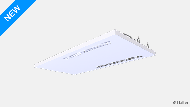
浩盾 Vita 患者 Ava (VPA)是一个完整的病房解决方案,集成辐射制冷和加热,并结合了独特的保护气流模式。浩盾 VPA 为患者提供舒适的室内气候条件,为医务人员提供安全的工作环境。
浩盾 Vita 患者 Ava 是浩盾 Vita 患者解决方案的一部分。
- 低而光滑的设计,表面卫生,易于清洁。
- 自动化系统具有易于使用的界面,确保在不同操作模式下的灵活性和最佳功能。
概览
浩盾 Vita 患者 Ava (VPA)是一个完整的病房装置,集成辐射制冷和制热,并结合了独特的保护气流模式。浩盾 VPA 为患者提供舒适的室内气候条件,为医务人员提供安全的工作环境。 浩盾 Vita 患者 Ava (VPA)是浩盾 Vita 患者解决方案的一部分。
应用
- 医院病房
主要特点
- 辐射制冷和制热,并带有送风分配,以满足舒适和最佳的室内气候条件。
- 保护性气流模式,为患者和医务人员提供安全的环境。
- 低而光滑的设计,表面卫生,易于清洁。
- 适用于天花板整合暗装或明装
- 病房操作模式控制的完整解决方案。
- 自动化系统,易于使用的界面,可以确保在不同操作模式下的灵活性和最佳性能。
工作原理
浩盾 Vita 患者 Ava (VPA) 将送风分配和辐射板与自动化相结合,使其成为病房的完整解决方案。
辐射板用于确保个人的热舒适性。通过辐射板铜管里的水流,冷热量传导至铝板,铝板作为辐射表面将温度传递至周围环境。
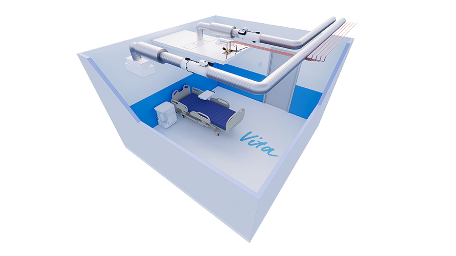
保护气流模式
为了降低感染风险并加强对医务人员的保护,浩盾 Vita 患者 Ava (VPA)提供了独特的保护气流模式。该解决方案通过产生一个来自送风的屏障来保护医务人员,同时保持患者的热舒适。
当配备浩盾 Vita 病房自动化系统和VAV变风量阀时,浩盾 Vita 患者 Ava (VPA)具有三种不同的操作模式:
- 空病房待机(分钟)—— 与有人时的(正常)操作模式下配置的气流速率相比,浩盾 Vita 病房自动化控制器可降低气流速率。
- 有人时(正常),对于有一个或多个患者的房间 —— 根据病房中的患者数量配置气流速度,浩盾 Vita 病房自动化控制器保持配置的气流速度。
- 增压(最大值),适用于医务人员或其他人员与患者在同一病房的情况——浩盾 Vita 病房自动化控制器可增加气流速度。
在增压操作模式下,送风气流旨在产生保护性气流模式,防止患者呼出的细菌进入医务人员的呼吸区。同时,新鲜、清洁的空气被带到医务人员的呼吸区。
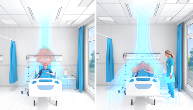
图 2. 保护气流模式。左:正常模式。右:保护气流模式的增压模式。
热舒适性
浩盾 Vita 病房自动化系统的设计可以使每个患者都能对房间进行单独控制,从而使患者能够根据自己的需求控制温度水平。温度水平通过调节铜管中循环水的流速和温度来控制。因此,患者的热舒适度得到了优化。如有必要,还可通过增加气流速度来增强制冷量。
制冷制热量
辐射板的冷却量根据EN 14240进行测量。安装类型(天花板一体化暗装或明装)会影响输出性能。因此,在浩盾 HIT设计软件中,可以检查每种情况下的制冷和制热量,应选择安装类型以获得更具体的输出数据。
辐射板的制热量根据EN 14037:2016进行测量。浩盾辐射板的制热量已在经认证的第三方实验室进行测量,以满足EN 14037-2的要求。
关键技术数据
| 属性 | 描述 |
| 气流 | 10…70 l/s |
| 尺寸 | 2400×1200 mm 或 3000×1200 mm |
| 管道连接 | ø 160 mm |
| 制冷量 | 最高 785 W (Tr 24°C, Ts 18°C, qvair 70 l/s, Tw 15°C, qmwater 0.035 kg/s) |
| 制热量 | 最高 605 W (Tr 20°C, Ts 20°C, Tw 50°C, qmwater 0.030 kg/s) |
| 重量 | 36.8…67.1 kg (不包括水) |
属性与选项
| 类别 | 属性 | 选项 |
| 尺寸 | 长度 |
|
| 宽度 | 标称宽度 1200 mm | |
| 制冷和制热 | 循环次数 |
|
| 水阀和执行器 |
|
|
| 自动化 | 系统包 |
|
| 气流 | 喷嘴散流器 | 始终包含 |
| 连接类型 |
|
|
| VAV 风闸 |
有关这些 VAV |
|
| 表面处理 | 颜色 | 白色抗菌环氧聚酯粉末涂料(RAL 9003)。 标准白色可选。 |
| 附件 | 消声器 | 带或不带消声器。 有关选项的信息,请参阅订购代码。 |
有关订购代码的信息,请参阅订购代码。
浩盾 Vita 患者 Ava 产品模型
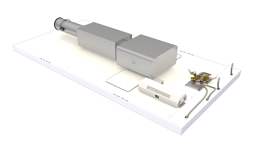
图 3. 带自动化功能的 浩盾 Vita 患者 Ava 室内装置(配备浩盾 Vita 室内自动化控制器装置、VAV 阀、消声器器、静压箱、水阀和执行器的辐射面板)
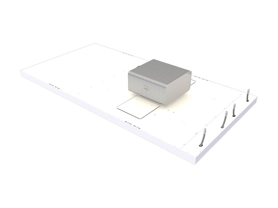
图 4. 浩盾 Vita 患者 Ava 不带自动控制的房间设备(辐射面板,配有包括手动气流风闸在内的管道箱)。
系统包
当产品打算配备浩盾 Vita VRA 病房自动化系统时,应在浩盾 Vita 患者 Ava (VPA) 产品订单代码中选择系统包。
该套件包括一个控制器装置和一个用户面板,用于调节医院病房的通风气流、室温和照明。
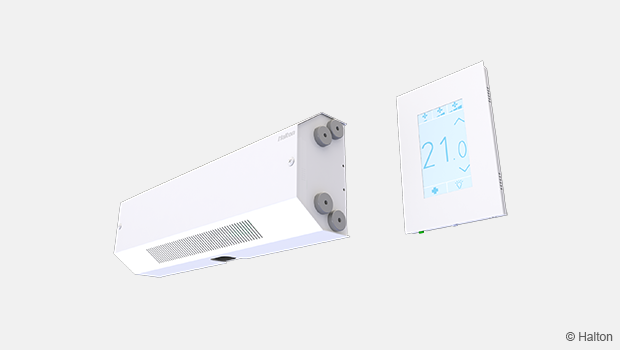
图 5. 自动化控制装置和用户面板
控制器装置安装在面板顶部,用户面板安装在墙上。
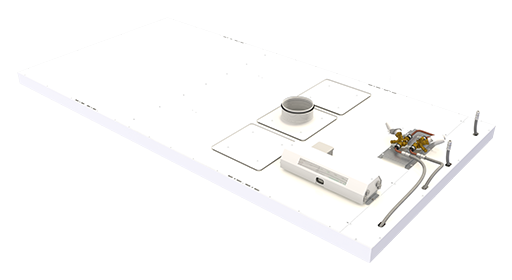
图 6. 系统包组件位置
有关系统包的更多详细信息,请访问 浩盾 Vita VRA病房自动化产品页面。
规格
- 专为医院病房设计的房间设备。
- 结合了辐射制冷和供暖以及送风分配功能。
- 病房设备配有自动化系统,可实现三种不同的运行模式、气流控制以及病房的温度和照明控制。
- 预编程和预测试的自动化系统包括一个卫生用户面板,用于调节运行模式、室内温度和室内照明。
- 有了自动化系统和 VAV 气流风闸,病房设备就能提高气流速度,提供保护医务人员免受病人呼出的细菌感染的气流模式。
结构
- 设备长度 2400 或 3000 mm.
- 设备宽度 1200 mm, 厚度 75 mm.
- 进气管直径 160 mm.
- 管道最大工作压力 1.0 MPa.
- 有两个检修口,可以清洁设备的气室。
材料
- 前面板由铝制成。
- 管道连接件和相关部件由镀锌钢制成。
- 所有可见部分均涂漆。白色抗菌环氧聚酯粉末涂料(RAL 9003)。
- 所有管道均由铜制成。
- 所有管接头均焊接。
- 所有管接头均在工厂经过压力测试。
包装和标识
- 产品的可见表面有一层可拆卸的塑料涂层保护。
- 管道连接处和管道末端在运输过程中保持密封。
- 产品包装在托盘上。
- 产品和包装上都贴有标签,上面印有产品的序列号。
设计信息
在设计病房时,请考虑以下几点:
- 为确保保护性气流模式,应在病房内每张病床上方安装浩盾 Vita Ava 病房设备。
- 是否同时需要制冷和制热功能?
- 室内机可以配备一个或两个水回路。通常情况下,环路 1 用于制冷,环路 2 用于制热。
- 为了帮患者进行单独的温度控制,建议病房设备配备两个水回路(制冷和制热)和 浩盾 Vita 病房自动化。
- 如果病房内有多张病床,建议为每个病人单独调节气流和温度。这样可以为医护人员或单个病床周围的其他人提供保护性气流模式。
- 如果需要,也可以将整个房间作为一个区域进行控制。在这种情况下,气流风闸位于房间的主管道中,而不是房间单元的分支中。
- 是否可以打开病房的窗户?
- 如果可以打开房间的窗户,建议使用窗户开关。窗户开关可检测窗户是否打开或关闭。如果窗户打开,则关闭制冷阀以防止冷凝。窗户开关是一个单独的附件,需要在设计文件中注明。
- 如何控制病房内的灯光?
- 浩盾Vita病房自动化控制器使用数字可寻址照明接口(DALI)控制照明:开关灯、调光或分组控制灯。
安装
浩盾 Vita Ava病房设备适用于集成天花板和明装天花板安装。
为确保保护性气流模式,应将 Halton Vita Ava 病房设备安装在病房内每张病床的上方。带水接口的一端应位于病床床头上方。末端墙壁与设备之间的距离应为 600 mm。
从前端面板的最低点到天花板的自由高度要求为 341 mm。
设备周围必须预留足够的空间用于维护。如果是实心天花板,则必须在靠近设备的地方设置一个检修口,以便能够进入设备顶部。
安装时,可使用电线和卡钩将设备悬挂在天花板上。
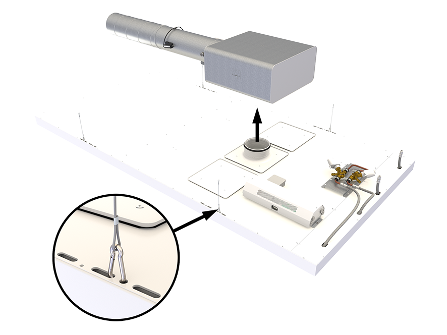
图 7. 浩盾Vita 患者 Ava安装
注意:交货中不包括电线、卡钩和软管
调试
气流调节
为实现保护气流模式,喷嘴朝向室内装置的纵向中心线。如有必要,可以调整喷嘴的方向。
冷却
建议的冷却水流量为 0.020…035 kg/s,辐射板的温升为 1…3°C。为避免冷凝,建议进水温度高于房间的露点温度。
加热
建议加热水的流量为 0.015…0.030 kg/s,使辐射板的温度下降 3…10°C。在典型房间(房间高度不超过 3 米)中,通常建议进水的最高温度为 50°C,因为辐射不对称的风险过高。
结构和材料
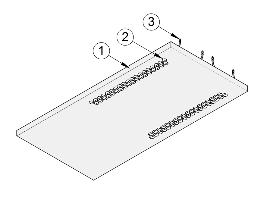
图 8. 浩盾Vita Ava 病房装置结构,底视图
| 编号 | 部件 | 描述 |
| 1 | 前端面板 | 预涂漆铝材。白色抗菌环氧聚酯粉末涂料 (RAL 9003)。标准白色可选。 |
| 2 | 气流喷嘴 | 塑料(聚缩醛) |
| 3 | 辐射板连接管 | 带推入式接头的连接管:不锈钢,ø 10 毫米 |
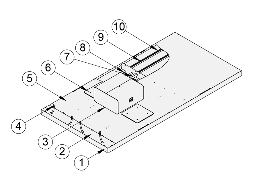
图 9. 浩盾Vita Ava 病房装置结构,顶视图
| 编号 | 部件 | 描述 |
| 1 | 前端面板 | 预涂漆铝材。白色抗菌环氧聚酯粉末涂料 (RAL 9003)。标准白色可选。 |
| 2 | 盖板 | 铝 |
| 3 | 静压箱 | 不锈钢, 管道连接: ø 160 mm |
| 4 | 辐射板连接管 | 带推入式配件的连接管:不锈钢,ø 10 mm |
| 5 | 顶盖板 | 铝 |
| 6 | 检修口 | 镀锌板 |
| 7 | 吸音材料 | 聚酯纤维 |
| 8 | 气流喷嘴 | 塑料(聚缩醛) |
| 9 | 辐射板管 | 铜, ø 10 mm |
| 10 | 管道固定型材 | 铝 |
尺寸和重量
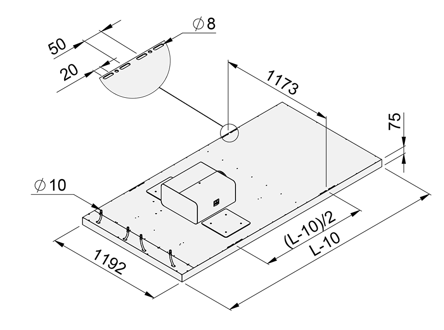
图 10. 浩盾 Vita Ava 病房装置尺寸 长度= 2400 或 3000 mm.

图 11. 浩盾Vita 患者 Ava病房装置, 侧视图
重量
| 装置长度 [mm] | 水循环次数 | 无自动化面板,干重 [kg] | 带自动化面板, 干重 [kg] | 水重 [kg] |
| 2400 | 1 | 36.8 | 55 | 4.6 |
| 2400 | 2 | 40.7 | 59.9 | 6.7 |
| 3000 | 1 | 43.1 | 61.3 | 5.7 |
| 3000 | 2 | 47.9 | 67.1 | 8.4 |
保养
前端面板和其他可见的油漆板可用湿布擦拭。设备可以使用过氧化氢进行室内消毒。
有两个检修口,可以清洁设备的气室。
如果明装,建议用吸尘器清洁设备顶部。
关于清洁频率,请遵循大楼的维护计划。
产品选型示例
在单人病房中使用 VRA 控制器单独控制一个 VPA 病房单元
描述
在此配置中,浩盾Vita病房自动化(VRA)控制器控制一个Halton Vita患者病房(VPA)装置。VPA 病房装置配有加热和冷却风闸以及 VAV 阀。该系统还包括一个 VRA 用户面板、一个窗户开关和一个排气 VAV 阀。一个 VRA 控制器可单独控制两个 VPA 病房装置,一个房间内可有多个 VRA 控制器。
设计标准
- 病房内有一张病床
- VPA 病房装置配有加热和冷却阀
- VPA 病房装置配有电动 VAV 阀 (MOC/MUC)
- VPA 病房装置配有单独的 VRA 控制器
- 通过电动 VAV 阀 (MOC/MUC) 控制排气气流
示意图
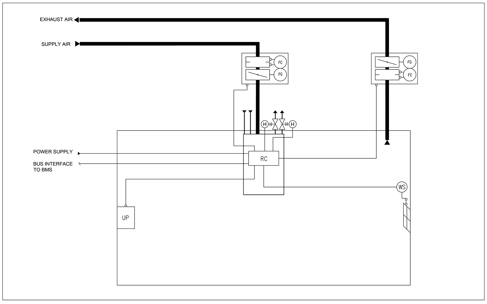
图 12. 示意图:在单人病房中使用 VRA 控制器单独控制一个 VPA 病房单元
| 代码 | 设备 |
| UP | VRA 用户面板 |
| RC | VRA 控制装置 |
| FG | 气流风闸执行器 |
| FC | 气流测量 |
| H | 水阀执行器 |
| WS | 窗户开关 |
系统订单代码示例
- 1 x VPA 病房装置,配有加热和冷却阀、VAV 风门和冷凝传感器
代码示例:
VPA-3000-1200,NL=2,SP=Y,ND=Y,CV=L1,CT=D,VD=MO,SA=H1,CO=SA - 1 x VRA 控制装置,带 VRA 用户面板和窗口开关
代码示例:
VRA/VPA-PA-VR-VC,CP=C1,LC=NA,CV=L1,FS=DC, WS=W1,EL=NA,ZT=N - 1 x 带消声器的 MOC VAV阀
代码示例:
MOC/G-160,MA=CS,CU=EM,FS=DS,SA=H1,RH=NA,ZT=N
在双人病房中,两个 VPA 病房装置与一个 VRA 控制器并行控制
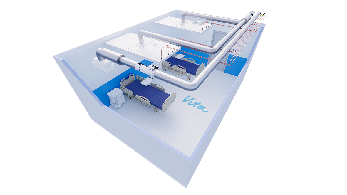
图 13. 在双人病房中,两个 VPA 病房装置与一个 VRA 控制器并行控制
描述
在此配置中,浩盾 Vita 病房自动化(VRA)控制器可控制双人病房中的两台浩盾 Vita 患者 Ava(VPA)病房装置。加热和冷却阀门位于主管道中。基本供货中不包括阀门和阀门执行机构。送风 VAV 阀位于主管道中。该系统还包括一个 VRA 用户面板、一个窗户开关和一个排气VAV 阀。
设计标准
- 一个病房两张病床
- 暖气和冷气阀门位于房间的主管道中
- 送风风闸位于病房的主管道内
- VPA 病房装置有一个共同的 VRA 控制器
- 通过电动 VAV 阀(MOC/MUC)控制排风量
示例图:
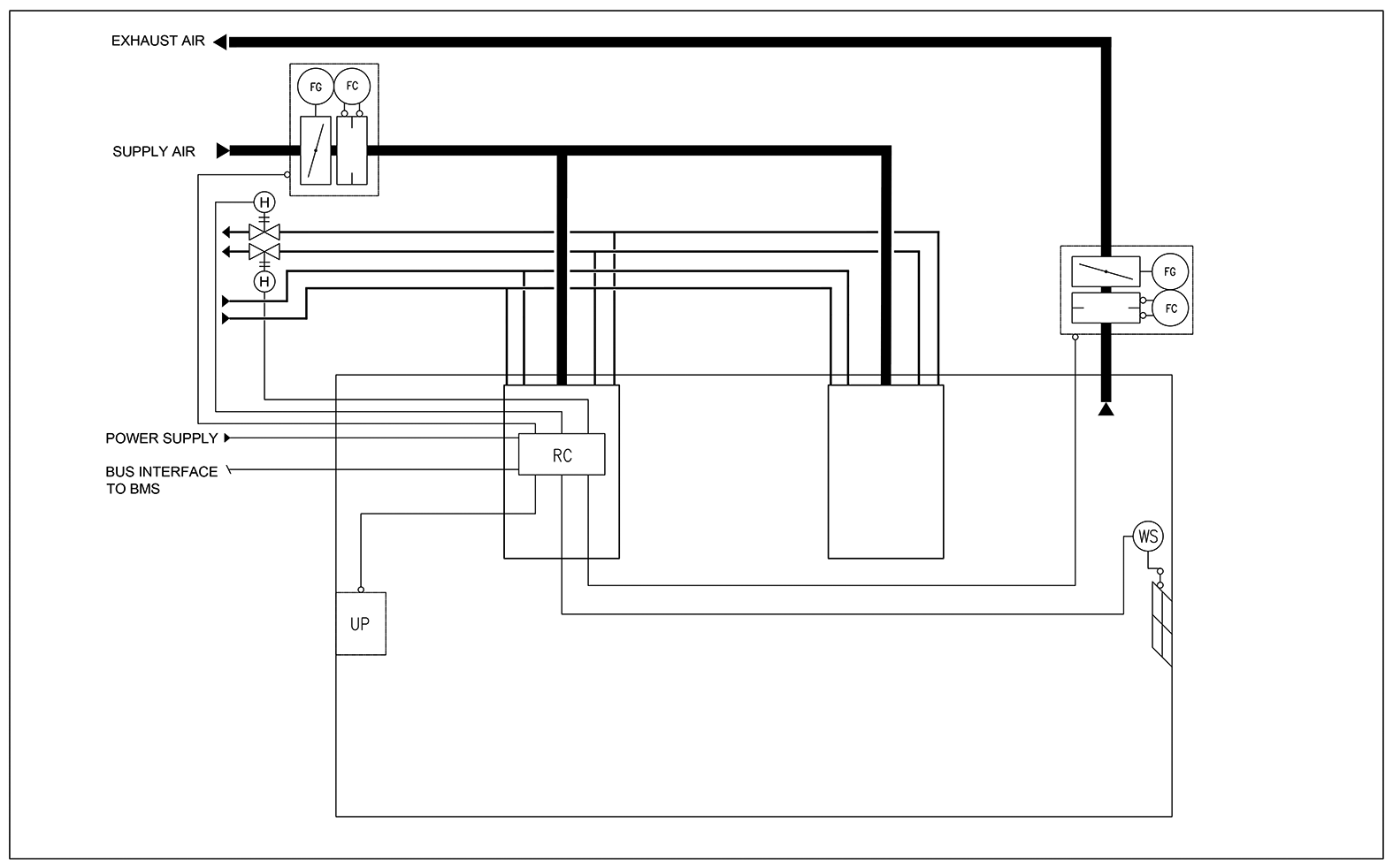
图 14. 示例图: 在双人病房中,两个 VPA 病房装置与一个 VRA 控制器并行控制
设备列表
| 代码 | 设备 |
| UP | VRA 用户面板 |
| RC | VRA 控制装置 |
| FG | 气流风闸执行器 |
| FC | 气流测量 |
| H | 水阀执行器 |
| WS | 窗户开关 |
系统的订单代码示例
- 2 个带加热和冷却功能的 VPA 病房装置
代码示例:
1x VPA-3000-1200,NL=2,SP=Y,ND=Y,CV=NA,CT=D,VD=MO,SA=H1,CO=SA
1x VPA-3000-1200,NL=2,SP=N,ND=Y,CV=NA,CT=D,VD=NA,SA=NA,CO=SA - 1 x VRA 控制单元,带 VRA 用户面板和窗口开关
代码示例:
VRA/VPA-PA-VR-VC,CP=C1,LC=NA,CV=L1,FS=DC,WS=W1,EL=NA,ZT=N - 1 x MOC 带消声器VAV阀,用于排气
代码示例:
MOC/G-200,MA=CS,CU=EM,FS=DS,SA=H1,RH=NA,ZT=N
订单代码
VPA/L-W-NL; SP-ND-CV-CT-VD-SA-CO
S = Length (mm)
2400, 3000
W = Width (mm)
1200
NL = Number of loops
1 1 loop (cooling or heating)
2 2 loops (cooling and heating)
Other options and accessories
SP = System package
N No
Y Yes
ND = With nozzle diffuser
Y Yes
CV = Water valves and actuators
NA Not assigned
L1 Linear, 0-10V
CT = Connection type
C Plenum box with MSM
D Plenum box without MSM
VD = With VAV damper
NA Not assigned
MO MOC + LMV-D3-MF-F.1 HI (EM)
MO1 MOC + GDB181.1E/3 (EH)
MU MUC + GDB 161.1E (G2)
SA = Sound attenuator for VAV damper
NA Not assigned
H1 L = 600 mm; Outlet = Inlet; Mineral wool
H2 L = 1000/1250 mm; Outlet = Inlet; Mineral wool
H3 L = 600 mm; Outlet = Inlet; Polyester fibre
H4 L = 1000/1250 mm; Outlet = Inlet; Polyester fibre
CO = Colour
SA Signal white, antibacterial (RAL 9003)
SW Signal white (RAL 9003)
Code example
VPA-3000-1200, SP=Y,NL=1,ND=Y,CV=L1,VD=NA,CT=NA,SA=NA,CO=SA
Downloads
"*" indicates required fields