Product / CPT
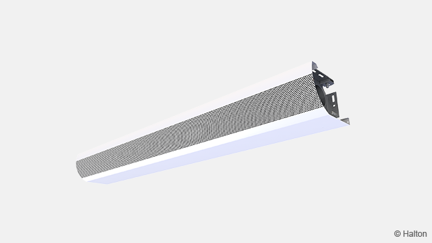
CPT 用于横向送风的方形送风装置
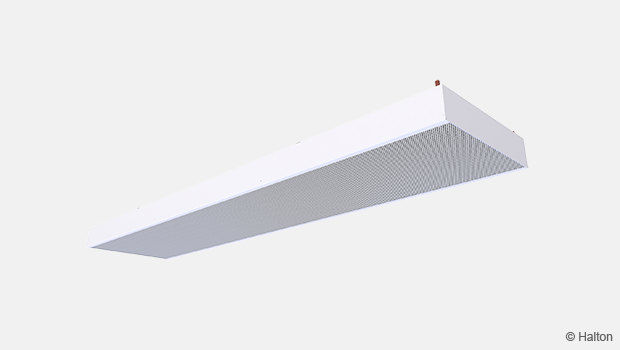
用于安装在网眼或孔板吊顶上的被动式冷梁,是高空间的理想之选。
概览
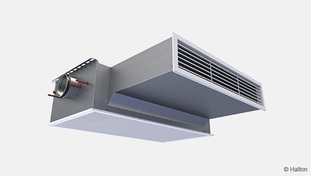
- 安装在吊顶上的被动式冷梁
- 安装在网眼或穿孔吊顶的上方
- 工作状态安静
- 无运动部件
- 对于要求高冷负荷、低度负荷和低通风的空间而言,是最佳选择
- 对于要求高品质环境条件和独立房间控制的各种建筑而言,是理想选择
- 典型应用环境:办公室、会议室和零售商店
- 装置的三种不同高度可满足不同的制冷能力要求Halton专注于提供定制产品以满足项目的特殊要求。可提供特殊尺寸和不同种类的集成设计方案。
尺寸和重量
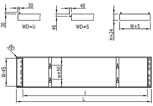
WD = 管道连接位置
U Front end
S On top
| W | H | w | L | l (without valves) | l (with valves) |
| 315 | 100 | 136 | 1200-5000 | L-200 | L-300 |
| 450 | 100 | 204 | 1200-5000 | L-200 | L-300 |
| 585 | 100 | 271 | 1200-5000 | L-200 | L-300 |
| 315 | 200 | 136 | 1200-5000 | L-200 | L-300 |
| 450 | 200 | 204 | 1200-5000 | L-200 | L-300 |
| 585 | 200 | 271 | 1200-5000 | L-200 | L-300 |
| 315 | 300 | 136 | 1200-5000 | L-200 | L-300 |
| 450 | 300 | 204 | 1200-5000 | L-200 | L-300 |
| 585 | 300 | 271 | 1200-5000 | L-200 | L-300 |
1 个线圈的连接管直径为 15 mm,2 个线圈的连接管直径为 22 mm。
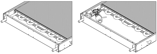
图1. 可选择出厂安装阀门
重量 kg/m (包含水)
| Width (mm) | Heigth (100-300) |
| 315 | 8,3 (8,5) |
| 450 | 10.8 (11.9) |
| 585 | 12.7 (14.1) |
Due to fabric skirts the weight difference between different heights is not remarcable.
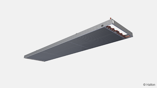
材料
| 部件 | 材料 | 备注 |
| 侧板 | 钢板 | 未喷涂 |
| 制冷管 | 铜 | 直径 15 mm |
| 制冷翅片 | 铝 | |
| 调节织物 | 防火聚酯 | 符合PES FR |
附件
| 附件 | 代码 | 备注 |
| 管道连接,末端为直管 | WD=S | |
| 管道连接,在顶部 | WD=U | |
| 工厂安装的控制阀 | CV = | 参见产品代码页面 |
其他选择请咨询浩盾客户服务部门。
功能
冷梁通过自然对流运行,带走室内的热负荷,并用冷却气流取而代之。对流气流(输出量)会根据占用区域内的热负荷按比例增加或减少,从而确保最佳的热舒适性。
通过调节流经冷梁热交换器的冷冻水流量,可满足不同的显冷输出要求。这由室内恒温器和水阀组合控制。在较高的冷冻水温度下运行(以避免潜冷),自由冷却的机会很大。
浩盾CPT 可以配备有三种不同高度的遮挡板,以满足不同的冷却能力要求。
安装
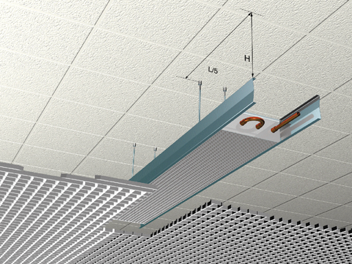
冷梁 Halton CPT 安装在开放式网格或穿孔天花板上方。
为确保有效对流,在远离墙面安装时,冷梁与天花板的最小距离应为 0.25 x 冷梁宽度;在靠近隔墙安装时,最小距离应为 0.5 x 冷梁宽度。
每根冷梁都用膨胀锚和螺纹拉杆(不包括在供货中)固定在天花板上。四个组装支架固定在距离梁端五分之一长度(L/5)处。冷梁长度 ³ 3500 时将有六个组装支架。
支架的准确位置可根据杆的位置进行调整。
冷梁位置易于水平和垂直调整。组装支架是包装中的标准配置。
承包商应提供螺纹杆和膨胀锚。
悬杆之间的距离
与天花板的距离
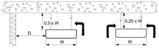
D = 与墙距离; 最高 1 x W
调节
冷梁系统的调试按照标准做法进行:
- 填充和冲洗主管道
- 对冷梁回路进行注水和排气
- 调整水流温度设定点
- 用平衡阀调整所有主管道的水流量
- 将所有冷梁的水流量调整到正确值
Servicing
浩盾 CPT 冷梁几乎不需要维护。
根据室内条件和空气质量,可能需要每三到五年清洁一次冷却盘管。通常可以使用真空吸尘器清洁。
规格
输出/容量 90 – 550 W/m
长度 1000, +100, .., 5000 mm
宽度 315, 450 和 585 mm
热交换器由铝翅片和标称外径为 15 mm的铜管构成。
冷水管工作压力最大为 1.0 兆帕。所有接头均完全焊接,并在出厂前进行了压力测试。
订单代码
CPT-L-W-NW-H;CO-WD-CV-ZT
L = Length
1200,+100,…, 5000
W = Width
315, 450, 585
NW = Number of water loops
1, 2
H = Height
100, 200, 300
Other Options and Accessories
CO = Colour
N No painting
B Black (RAL 9005, 20%)
WD = Location of pipe connection
S Front end
U On top
CV = Control valve
N No
A1 Adjust. kv value, factory mounted, no actuator
A3 Adjust. kv value, factory mounted, 24-V actuator
A5 Adjust. kv value, factory mounted, 230-V actuator
A7 Constant-flow-mounted, no actuator
A9 Constant-flow-mounted, 24-V actuator
A11 Constant-flow-mounted, 230-V actuator
ZT = Tailored product
N No
Y Yes
Code example
CPT-2200-585-1-100, CO=N, WD=S, CV=N, ZT=N
Downloads
"*" indicates required fields