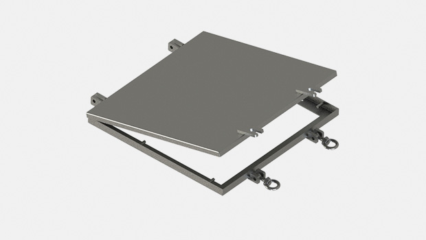
Product / DSA
DSA – Séparateur d’embruns chauffant
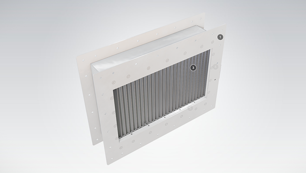
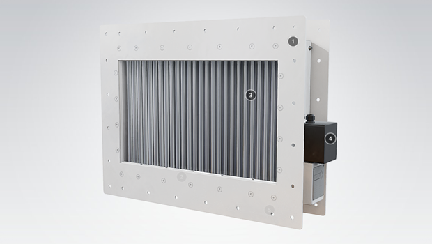
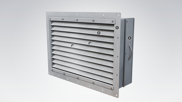
Halton’s DSA high-efficiency droplet separators are designed for demanding applications such as oil & gas, chemical, energy and marine industries, where reliability, easy installation and special design play an important role. Droplet separators are designed to restrict the passage of moisture, salt spray, rainwater and airborne aerosol particles e.g. into HVAC systems, engine room intakes, machinery spaces, and diesel and gas turbine air intakes.
Overview
- High droplet and moisture separation efficiency
- Class A results (EN 13030:2001)
- Minimum pressure drop
- Performance tested according to EN 13030:2001 test for louvres subjected to simulated rain, at the independent laboratory
- Tailored sizes and designs according to customer’s needs. Modular construction is available.
- For wall and duct installations
- No special maintenance required
- ATEX certified components II 2 G/D EEx e II T3/T2
- Heating capacity 2,5 kW/m2 – 3,7kW/m2
- Operating temperature for DSA -50 ºC – +40 ºC
- An Extreme Conditions Solution available
- Stainless steel junction box available as an option
Specification
DSA droplet separators are fitted with heating elements. The regulated temperature is subject to the surrounding conditions. The actual surface temperature of the heated DSA depends on many variables such as the size of the separator, wind circumstances, face velocity, air temperature and relative humidity. Electrical heating capacities vary between 2,5 kW/m2 – 3,7 kW/m2, depending on these conditions. The cable heating does not prevent icing in the most severe conditions, but it will help defrost the ice when the icing conditions have passed.
When intake air is crucial during extreme icing conditions the Halton ECS (Extreme Conditions Solution) keeps the air intake open. The ECS is available as an option.
Dimensions
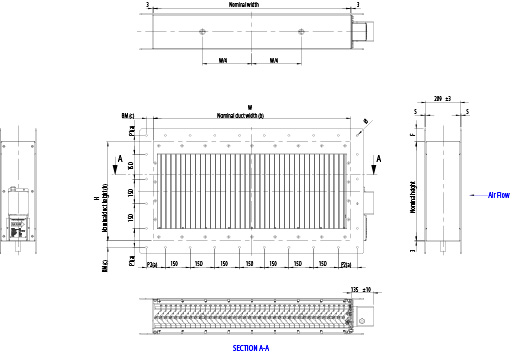
Please note
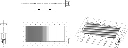
- 75 mm
- Width x Height = nominal duct size (internal)
- Back mark BM is the distance from the inside
duct to centerline hole
Frame options
- Flange only in front
- Flange only in back
- Flange in front and back
- Without a flange
Flange drilling ISO15138 as standard.
| Nominal duct Longest side (mm) |
Back mark BM (mm) |
Flange F (mm) |
Bolt hole size Ø (mm) |
Aluminium Flange thickness S (mm) |
Stainless steel Flange thickness S (mm) |
| < 350 | 20 | 40 | 10 | 5 | 3 |
| > 350 to > 1000 | 30 | 50 | 12 | 5 | 3 |
| > 1000 | 40 | 80 | 14 | 5 | 5 |
Minimum and maximum dimensions
A minimum size for Halton DSA droplet separator is 300×300 mm (WxH). Maximum size for a single separator is 1500×1200 mm (WxH). Sizes with 50 mm divisions. Modular construction available up to 3000×2400 mm (WxH).
Material thickness
Standard frame thickness 3 mm. Larger thicknesses available as an option.
Material and Finishing
| PART | MATERIAL | FISHING |
| Droplet separator | Aluminium EN AW 6060 | – |
| Frame | Aluminium EN AW 5754 | Painted RAL9010, C3 acc. standard* ISO 12944-2 as standard |
| Frame | Stainless steel EN 1.4404 (AISI 316L) | Painted as an option |
| Heating cable | Nickel-plated copper wire, silicone rubber outer jacket (ATEX certified) |
– |
| Junction box | GRP, Eex e II T6 IP66 | – |
*) C3 durability of 7-15 years. Please note about painting procedures; NORSOK C5-M and Norsok M501 available on request. Please note: Stainless steel junction box available as an option.
Electrical Data and Control
Power supply 230V, 1 Phase AC.
Electrical heating capacities vary between 2,5 kW/m2 – 3,7 kW/m2, depending on ambient temperature. For optimal performance and control, contact Halton Marine.
Drainage
Drain pipe
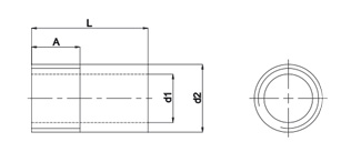
Threaded drain pipes are welded to the bottom of the droplet separator. The thread type is 1″ BSPT (male).
Drain locations
Drain pipe sizes
| Weld-on pipe | Ø (Inch) | L (mm) | A (mm) | d1 (mm) | d2 (mm) |
| Aluminium EN AW 6060 | 1 | 50 | 25 | 25 | 35 |
| Stainless steel EN 1.4404 (AISI 316) | 1 | 40 | 20 | 27 | 34 |
Optional Features
The Extreme Conditions Solution (ECS)
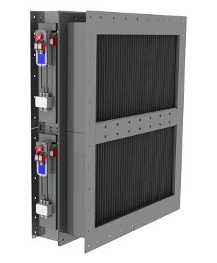
When intake air is crucial during extreme icing conditions, the Halton Extreme Condition Solution (ECS) keeps the air intake open. The Halton ECS combines the DSA heated droplet separators with either shut-off or fire dampers with an additional option for filter units.
The solution can allow one or more separators to remain open and ice-free while the other separator is in defrost mode during critical atmospheric conditions.
This is achieved by shutting-off a section of the DSA to allow the ice build-up to melt.
There are a few control methods available to alternate the opening/closing sequence of the ECS to ensure a free flow of unrestricted air.
“Gooseneck” – Reducing the wind effect
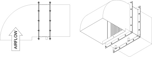
Strong wind can adversely affect the performance of the droplet sepator. In environments where stormy weather is regular Halton recommends using a “gooseneck” air intake with droplet separators. A gooseneck can be installed directly to a duct installation type of droplet separator.
Filters
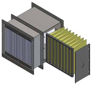
Please note: filters installed in DSA require always a separate frame.
ISO Coarse 70% filter
Panel filters are manufactured of progressive thermally smoothened synthetic polyester having high dust holding capacity and constancy for humidity. The filters are used in general ventilation system for air purification.
ePM10 70%, ePM2,5 65%, ePM1 50% Bag filters
The materials of the synthetic fine filters are high-quality and durable, progressive mounted synthetic fibres. The filters can be used in example for air purification of intake air.
ATEX approved filters
Halton Marine also offers ATEX approved filters for droplet separators.
Installation in conjunction with damper
Halton droplet separator can be connected to a Halton Marine damper with or without a connection piece. In both cases the construction is modified to fit the damper. Connecting DSH together with a fire damper must be mentioned when ordering products. Special flanges and drilling patterns are available for all models on request. The structural flexibility of dampers and high-quality combined with a wide range of accessories (ex-actuators) and special steels, enable Halton Marine to offer tailored solutions for its customers.
Combining Halton Marine droplet separator to damper offers customers a compact solution for air intake that also saves space. The products are recommended to be connected together at Halton Marine factory.
Weather tight hatch
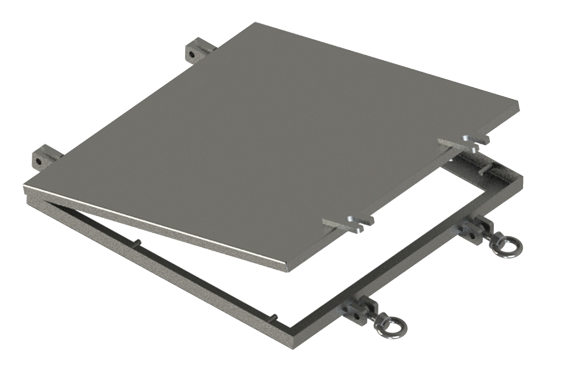
Weather tight hatch (WTH) is used e.g. to shut down the intake close to the waterline in the event of rough seas. See a separate brochure on weather tight hatch called Halton WTH.
Results
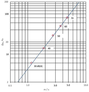
Pressure drop and sound data LPA[DB(A)]
DSA aluminium, pitch spacing 28 mm. Velocity based on face area
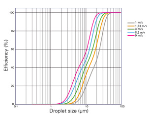
DSA efficiency results
Single stage DSA, pitch spacing 28 mm
Performance data
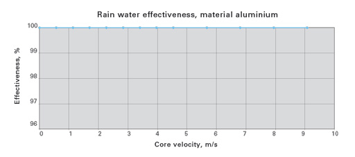
Effectiveness for removal of simulated rain
EN 13030:2001
Rainfall rate: 75 (l/h)/m2, (75 mm/h)
Vertical installation
Weights
Weights of DSA including frame, 1 flange, aluminium (KG), pitch spacing 28 mm
| H/HEIGHT mm | B / WIDTH (mm) | ||||||||||||||||||||||||
| 300 | 350 | 400 | 450 | 500 | 550 | 600 | 650 | 700 | 750 | 800 | 850 | 900 | 950 | 1000 | 1050 | 1100 | 1150 | 1200 | 1250 | 1300 | 1350 | 1400 | 1450 | 1500 | |
| 300 | 10 | 12 | 13 | 14 | 16 | 17 | 18 | 20 | 21 | 22 | 23 | 24 | 26 | 27 | 28 | 31 | 33 | 34 | 35 | 37 | 38 | 39 | 41 | 42 | 43 |
| 350 | 12 | 13 | 14 | 16 | 17 | 19 | 20 | 22 | 23 | 24 | 26 | 27 | 29 | 30 | 31 | 35 | 36 | 37 | 39 | 41 | 42 | 44 | 45 | 46 | 48 |
| 400 | 13 | 14 | 16 | 17 | 19 | 20 | 22 | 24 | 25 | 27 | 28 | 30 | 31 | 33 | 34 | 38 | 40 | 41 | 43 | 45 | 46 | 48 | 49 | 51 | 52 |
| 450 | 14 | 16 | 17 | 19 | 21 | 22 | 24 | 26 | 27 | 29 | 31 | 32 | 34 | 36 | 37 | 41 | 43 | 45 | 46 | 48 | 50 | 52 | 54 | 55 | 57 |
| 500 | 15 | 17 | 18 | 20 | 23 | 24 | 26 | 28 | 29 | 32 | 34 | 35 | 37 | 39 | 40 | 44 | 47 | 48 | 50 | 52 | 54 | 56 | 58 | 59 | 62 |
| 550 | 16 | 18 | 20 | 22 | 24 | 26 | 28 | 30 | 32 | 34 | 36 | 38 | 40 | 42 | 44 | 48 | 50 | 52 | 54 | 56 | 58 | 60 | 62 | 64 | 66 |
| 600 | 17 | 20 | 21 | 24 | 26 | 27 | 30 | 32 | 34 | 36 | 39 | 40 | 43 | 45 | 47 | 51 | 53 | 55 | 58 | 60 | 62 | 64 | 67 | 68 | 71 |
| 650 | 18 | 21 | 22 | 25 | 28 | 29 | 32 | 34 | 36 | 39 | 41 | 43 | 45 | 48 | 50 | 54 | 57 | 59 | 61 | 64 | 66 | 68 | 71 | 73 | 75 |
| 700 | 19 | 22 | 24 | 27 | 29 | 31 | 34 | 37 | 38 | 41 | 44 | 45 | 48 | 51 | 53 | 58 | 60 | 62 | 65 | 68 | 70 | 72 | 75 | 77 | 80 |
| 750 | 21 | 23 | 25 | 28 | 31 | 33 | 36 | 39 | 40 | 43 | 46 | 48 | 51 | 54 | 56 | 61 | 64 | 66 | 69 | 72 | 73 | 76 | 79 | 81 | 84 |
| 800 | 22 | 25 | 27 | 30 | 33 | 35 | 38 | 41 | 43 | 46 | 49 | 51 | 54 | 57 | 59 | 64 | 67 | 69 | 72 | 75 | 77 | 81 | 84 | 86 | 89 |
| 850 | 23 | 26 | 28 | 31 | 34 | 36 | 40 | 43 | 45 | 48 | 51 | 53 | 57 | 60 | 62 | 67 | 71 | 73 | 76 | 79 | 81 | 85 | 88 | 90 | 93 |
| 900 | 24 | 27 | 29 | 33 | 36 | 38 | 42 | 45 | 47 | 51 | 54 | 56 | 59 | 63 | 65 | 71 | 74 | 76 | 80 | 83 | 85 | 89 | 92 | 94 | 98 |
| 950 | 25 | 29 | 31 | 34 | 38 | 40 | 44 | 47 | 49 | 53 | 56 | 59 | 62 | 66 | 68 | 74 | 78 | 80 | 83 | 87 | 89 | 93 | 96 | 99 | 102 |
| 1000 | 26 | 30 | 32 | 36 | 40 | 42 | 46 | 49 | 52 | 55 | 59 | 61 | 65 | 69 | 71 | 77 | 81 | 83 | 87 | 91 | 93 | 97 | 101 | 103 | 107 |
| 1050 | 29 | 33 | 35 | 39 | 43 | 46 | 50 | 54 | 56 | 60 | 64 | 66 | 70 | 74 | 76 | 80 | 84 | 87 | 91 | 95 | 97 | 101 | 105 | 107 | 111 |
| 1100 | 30 | 34 | 37 | 41 | 45 | 47 | 52 | 56 | 58 | 62 | 66 | 69 | 73 | 77 | 80 | 84 | 88 | 90 | 94 | 99 | 101 | 105 | 109 | 112 | 116 |
| 1150 | 31 | 36 | 38 | 42 | 47 | 49 | 54 | 58 | 60 | 65 | 69 | 72 | 76 | 80 | 83 | 87 | 91 | 94 | 98 | 102 | 105 | 109 | 114 | 116 | 120 |
| 1200 | 32 | 37 | 40 | 44 | 48 | 51 | 56 | 60 | 63 | 67 | 72 | 74 | 79 | 83 | 86 | 90 | 95 | 97 | 102 | 106 | 109 | 113 | 118 | 121 | 125 |
The weights on the table are indicative and do not include a filter and damper.
Consult Halton Marine for weights for different types of configurations and weights for modular constructions.
A minimum size for Halton DSA droplet separator is 300×300 mm (WxH). Maximum size for a single separator is 1500×1200 mm (WxH). Sizes with 50 mm divisions. Modular construction available up to 3000×2300 mm (WxH).
Product code
(S)=Model
(A) Single W1H1
(B) Side by side W2H2
(C) One on the other W1H2
(D) Two by two W2H2
(W)=Width
300-1500 mm per module, max 2×2 modules
(H)=Height
300-1200 mm per module, max 2×2 modules
Specifics and accessories
(MP)=Module
(M1) Left upper module
(M1) Left upper module
(M2) Right upper module
(M3) Left lower module
(FM)=Frame Material
(AS) Stainless steel (EN 1.4404)
(LS) Stainless steel (EN 1.4432)
(AL) Aluminium EN AW 5754 (RAL9010 default paint)
(SM)=Separator Material
(AS) Stainless steel (EN 1.4404)
(AL) Aluminium EN AW 6060
(FT)=Frame type
(FD) Flange both sides (double)
(FF) Flange in front (front)
(FB) Flange in back (back)
(EX)=Safe area
(N) No
(Y) Yes
(ZT)=ETO Processing
(Y) Yes
(N) No
AC=Accessories
(MD) Manometric drain trap
Code example
DSA/A-300-300,MP=M1,FM=AL,SM=AL,FT=FD,EX=Y,ZT=N,AC=MD
Downloads
"*" indicates required fields
