Product / HFD
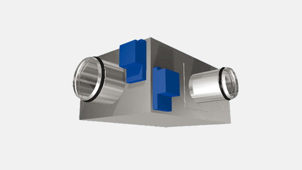
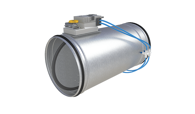
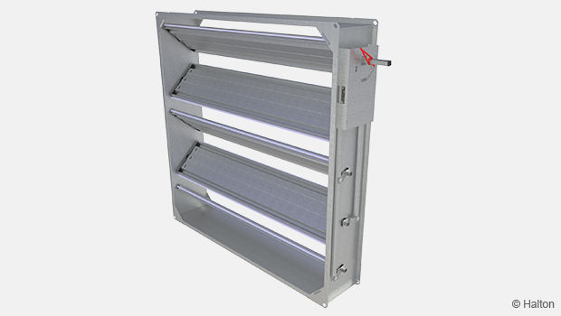
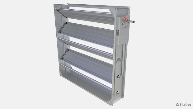
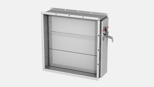
Halton HFD – Boîte de détente et de mélange
Arrêt de la production le 1.10.2021
-> non remplacé
- Boîte de détente double tube pour les utilisations en débit variable ou constant
- Fonctionnement indépendant de la pression amont
Présentation
Arrêt de la production le 1.10.2021
-> non remplacé
- Boîte de détente double tube pour les utilisations en débit variable ou constant
- Fonctionnement indépendant de la pression amont
- Fabrication en acier galvanisé avec isolation
- En position fermée, le clapet est étanche
- Raccordements avec un joint caoutchouc intégré
- Calibration des débits en usine (débits d’air mini/maxi)
OPTIONS
- Isolation complémentaire
- Silencieux
- Différents plénums de sortie
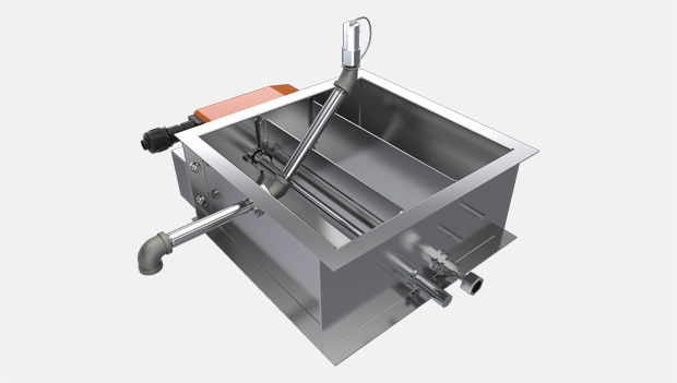
Introduction
HFD
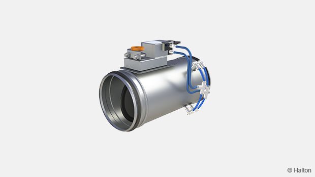
Airflow Management Damper for Dual Duct Systems

-
- Control damper for variable and constant airflow control applications in dual duct systems
-
- Pressure-independent operation
-
- Galvanised steel construction with insulation
-
- Tight shut-off operation at closed damper position
-
- Circular duct connection equipped with rubber gaskets
-
- Factory-set airflow range limits (min./max. airflow rates)
Product Models & Accessories
-
- Additional insulation option
-
- Sound attenuator
-
- Different outlet plenum options
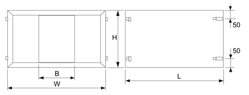
Dimensions
DIMENSIONS

HFD/S, mm
| NS | L | L1 | L2 | W | W1 | H | ØD | ØD1 |
| 125 | 720 | 600 | 285 | 486 | 330 | 225 | 125 | 100 |
| 160 | 720 | 600 | 285 | 486 | 330 | 260 | 160 | 125 |
| 200 | 720 | 600 | 333 | 611 | 435 | 300 | 200 | 160 |
| 250 | 720 | 600 | 403 | 641 | 435 | 350 | 250 | 200 |
| 315 | 1020 | 900 | 453 | 744 | 500 | 415 | 315 | 250 |
| 355 | 1020 | 900 | 525 | 829 | 585 | 455 | 355 | 250 |
| 400 | 1020 | 900 | 570 | 1021 | 715 | 500 | 400 | 315 |
| 500 | 1020 | 900 | 713 | 1296 | 950 | 600 | 500 | 355 |
HFD/B, mm
| NS | L | L1 | L2 | W | W1 | H | ØD | ØD1 |
| 125 | 760 | 640 | 325 | 486 | 410 | 305 | 125 | 100 |
| 160 | 760 | 640 | 325 | 486 | 410 | 340 | 160 | 125 |
| 200 | 760 | 640 | 373 | 611 | 515 | 380 | 200 | 160 |
| 250 | 760 | 640 | 443 | 641 | 515 | 430 | 250 | 200 |
| 315 | 1060 | 940 | 453 | 784 | 580 | 495 | 315 | 250 |
| 355 | 1060 | 940 | 525 | 869 | 665 | 535 | 355 | 250 |
| 400 | 1060 | 940 | 570 | 1051 | 795 | 580 | 400 | 315 |
| 500 | 1060 | 940 | 713 | 1326 | 1030 | 680 | 500 | 355 |
Version
S = Standard insulation, B = Extra insulation
Material
MATERIAL AND FINISHING
| PART | MATERIAL | NOTE |
| Casing | Galvanised steel | |
| Sound attenuation material |
Mineral wool | Surface protection layer |
| Damper blade | Galvanised steel | |
| Blade gasket | Neoprene | Sizes 100…315 |
| Blade gasket | EPDM rubber | Sizes 400 and 355 |
| Seals between accessories |
PVC rubber | |
| Duct gasket | EPDM rubber | |
| Measurement probe |
Aluminium |
Function
FUNCTION
Variable airflow setting
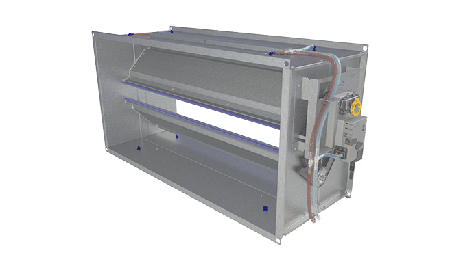
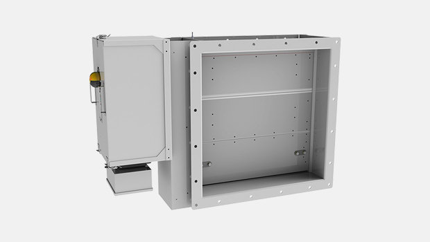
The cold and warm air ducts are connected to the mixing box. The cold duct connection size is equal to the nominal size of the device, and the warm duct connection is one duct size smaller. The mixing box is equipped with two electric airflow controllers.
In variable airflow application, the warm duct inlet is equipped with the airflow rate measurement probe, and the measurement probe of the outlet of the mixing box measures the total airflow rate. Based on the outlet airflow measurement, the mixed airflow rate is controlled so as to correspond to the total airflow setpoint regardless of the mixing ratio and duct pressure changes. The warm duct airflow rate, and consequently the mixing ratio, is controlled by the room temperature control signal according to the control sequence presented in the figure below. The control signals (heating and total flow) can be received from a stand-alone room controller or from a building management system.

Constant total airflow setting
The cold and warm air ducts are connected to the mixing box, and both duct connections are of equal size to the nominal size of the unit. The mixing box is equipped with two electric airflow controllers.
In constant airflow application, both duct inlet connections are equipped with airflow measurement probes. The mixing ratio and total airflow rate are controlled by building management system control signals (heating and cooling) so that the desired supply air temperature and airflow rate are obtained as described for the control sequence in the figure below.

Product Models
PRODUCT MODELS
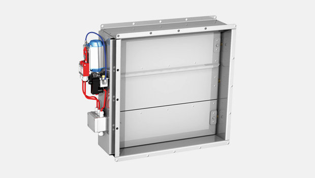
The HFD airflow management unit is available in several versions. An integral blade gasket enables tight shut-off operation, and external insulation is used to attenuate radiated sound into the space.
| MODEL | FEATURE | COMMENT |
| HFD/S | Supply air | Standard insulation: 25 mm |
| HFD/B | Supply air with extra insulation |
Insulation: 65 mm |
Control units (CU)
EE = Halton NMV-D2-MP
ED = Belimo VRD2+NM24A-V
EG = Siemens GLB181.1E/3
Controllers EE and ED include a dynamic differential pressure sensor with a low airflow rate through the sensor element. Therefore, these controllers shall not be used in highly contaminated environments. The pressure sensor of the EG unit is based on a membrane with no flow through the sensor element.
Controller ED includes two potentiometers for minimum and maximum airflow setpoint adjustment (ranges: minimum = 0…80% and maximum = 30…100%).
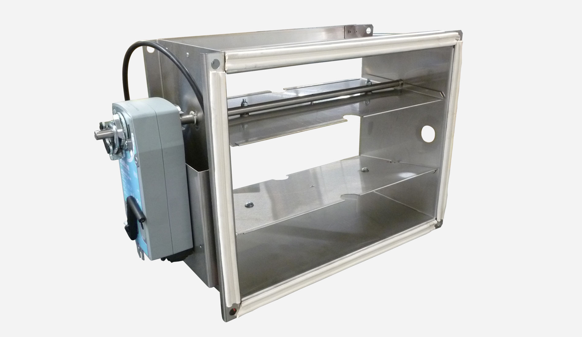
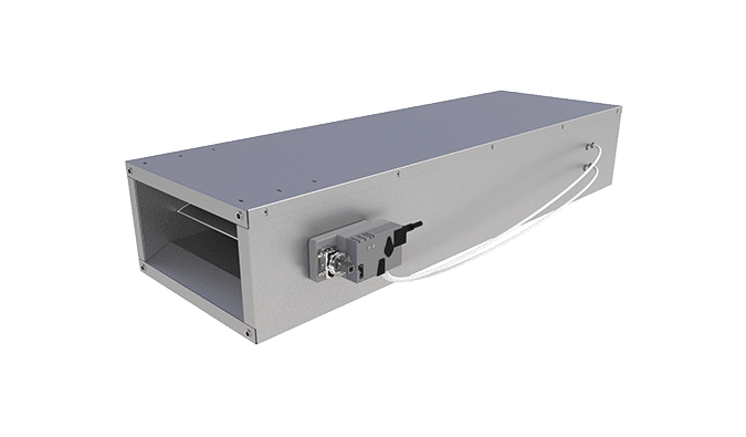
Sound Attenuators
SOUND ATTENUATORS
Sound attenuators are available 600 or 900 mm in length, with insulation material of mineral wool.
External insulation thickness corresponds to the HFD model, 25 mm or 65 mm.
Attenuator length:
– 600 mm is used for duct size range 100…250 mm.
– 900 mm is used for duct size range 315…500 mm.
SA = Attenuator with baffle
SX = Attenuator without baffle
SA/SX-HFD/S, attenuation material thickness of 25 mm
| NS | L | H | W | B | kg |
| 100 | 600 | 225 | 330 | 160 | 10.0 |
| 125 | 600 | 225 | 330 | 160 | 10.0 |
| 160 | 600 | 260 | 330 | 120 | 10.0 |
| 200 | 600 | 300 | 435 | 160 | 11.5 |
| 250 | 600 | 350 | 435 | 120 | 11.0 |
| 315 | 900 | 415 | 500 | 120 | 18.0 |
| 355 | 900 | 455 | 585 | 2×120 | 27.0 |
| 400 | 900 | 500 | 715 | 2×120 | 33.0 |
| 500 | 900 | 600 | 950 | 3×120 | 53.5 |
SA/SX-HFD/B, attenuation material thickness of 65 mm
| NS | L | H | W | B | kg |
| 100 | 600 | 305 | 410 | 160 | 14.0 |
| 125 | 600 | 305 | 410 | 160 | 14.0 |
| 160 | 600 | 340 | 410 | 120 | 15.0 |
| 200 | 600 | 380 | 515 | 160 | 16.5 |
| 250 | 600 | 430 | 515 | 120 | 16.0 |
| 315 | 900 | 495 | 580 | 120 | 21.0 |
| 355 | 900 | 535 | 665 | 2×120 | 32.0 |
| 400 | 900 | 580 | 795 | 2×120 | 42.0 |
| 500 | 900 | 680 | 1030 | 3×120 | 63.5 |
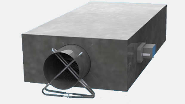
Connections
Connections
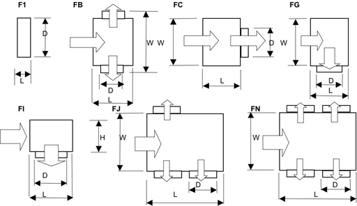
There are eight (8) different outlet connection options available for the HFD dual duct airflow management damper.
For constant airflow applications seven (7) connection models can be used:
- F1: This connection model is developed to connect circular duct directly to the HFD unit, without sound attenuator. If sound attenuator is used, please select the FC connection model in order to allow proper air mixing after sound attenuator.
- FB, FC, FG, FJ and FN: To connect one or more ducts to HFD unit. All these can also be used with sound attenuator.
- FI: This model is used to connect the HFD directly to a diffuser.
For variable airflow applications outlet duct connection model FT is used.
The connection module FT is equipped with a total airflow rate measurement probe.
e = attenuation material thickness [mm]
| HFD | e = 25 | e = 65 | F1 | FB | FC | FG | ||||||
| NS | H | W | H | W | 1 x D | L1 | 2 x D | L1 | 1 x D | L1 | 1 x D | L1 |
| 100 | 225 | 330 | 305 | 410 | 125 | 65 | 125 | 225 | 125 | 200 | 160 | 260 |
| 125 | 225 | 330 | 305 | 410 | 160 | 65 | 125 | 225 | 160 | 200 | 160 | 260 |
| 160 | 260 | 330 | 340 | 410 | 200 | 65 | 160 | 260 | 200 | 200 | 200 | 300 |
| 200 | 300 | 435 | 380 | 515 | 250 | 65 | 200 | 300 | 250 | 200 | 250 | 350 |
| 250 | 350 | 435 | 430 | 515 | 315 | 65 | 250 | 350 | 315 | 200 | 315 | 415 |
| 315 | 415 | 500 | 495 | 580 | 355 | 65 | 315 | 415 | 355 | 200 | 355 | 455 |
| 355 | 455 | 585 | 535 | 665 | 400 | 80 | 355 | 455 | 400 | 200 | 400 | 500 |
| 400 | 500 | 715 | 580 | 795 | 450 | 80 | 400 | 500 | 450 | 200 | 450 | 660 |
| 500 | 600 | 950 | 680 | 1030 | 500 | 80 | 500 | 660 | 500 | 300 | 500 | 660 |
| HFD | e = 25 | e = 65 | FI | FJ | FN | FT | ||||||
| NS | H | W | H | W | 1 x D | L1 | 3 x D | L1 | 4 x D | L1 | D | L |
| 100 | 225 | 330 | 305 | 410 | <=160 | 260 | 100 | 350 | 100 | 350 | – | – |
| 125 | 225 | 330 | 305 | 410 | <=200 | 260 | 100 | 350 | 100 | 350 | 125 | 395 |
| 160 | 260 | 330 | 340 | 410 | <=250 | 300 | 125 | 400 | 125 | 400 | 160 | 425 |
| 200 | 300 | 435 | 380 | 515 | <=315 | 350 | 160 | 470 | 160 | 470 | 200 | 425 |
| 250 | 350 | 435 | 430 | 515 | <=355 | 415 | 200 | 550 | 200 | 550 | 250 | 425 |
| 315 | 415 | 500 | 495 | 580 | <=400 | 455 | 250 | 650 | 250 | 650 | 315 | 425 |
| 355 | 455 | 585 | 535 | 665 | <=400 | 500 | 315 | 780 | 315 | 780 | 355 | 465 |
| 400 | 500 | 715 | 580 | 795 | <=500 | 660 | 355 | 860 | 355 | 860 | 400 | 465 |
| 500 | 600 | 950 | 680 | 1030 | <=500 | 660 | 400 | 950 | 400 | 950 | 500 | 465 |
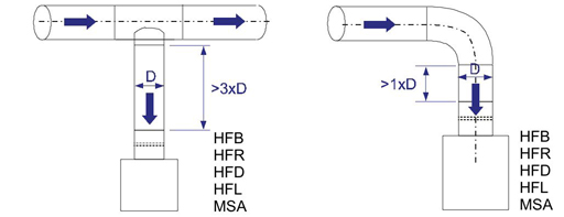
Installation
INSTALLATION
Safety distances
The airflow control damper is installed with attention to required safety distances (see figure).
Wiring
The wiring shall be carried out in accordance with local regulations and by professional technicians.
For the power supply of all control options a safety-isolating transformer shall be used.
HFD; CU=EE (NMV-D2-MP) – variable or constant airflow control
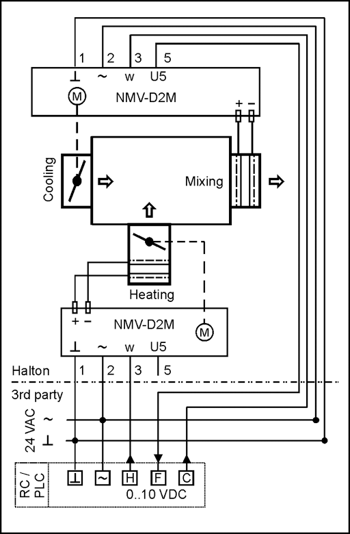
CODE DESCRIPTION
Halton Delivered by Halton
3 rd party Delivered by a third party
1 ( ^ ) 24 VAC system neutral
2 (~) 24 VAC live
3 (w) 0…10-VDC airflow setpoint signal input
5 (U5) 0…10-VDC airflow feedback signal output
RC Room controller
PLC Building management system
C(AO) Airflow setpoint, unit total airflow
H(AO) Airflow setpoint, heating
F(AI) Actual airflow feedback input
HFD; CU=EE (NMV-D2-MP) – variable or constant airflow control
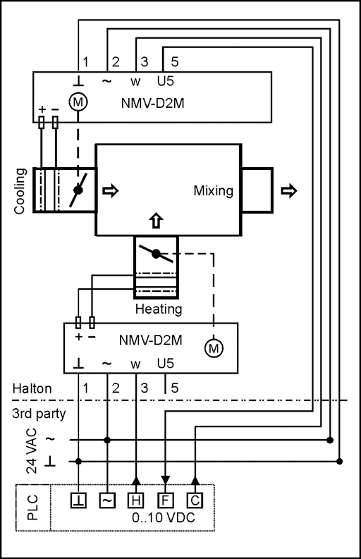
CODE DESCRIPTION
Halton Delivered by Halton
3 rd party Delivered by a third party
1 ( ^ ) 24 VAC system neutral
2 (~) 24 VAC live
3 (w) 0…10-VDC airflow setpoint signal input
5 (U5) 0…10-VDC airflow feedback signal output
RC Room controller
PLC Building management system
C (AO) Airflow setpoint control signal
F (AI) Actual airflow feedback input
Commissioning
COMMISSIONING
Airflow control
Nominal airflow rates of the HFD are presented in the table below.
| NS | qv_nominal | NS | qv_nominal |
| 100 | 73 l/s 263 m 3 /h |
315 | 874 l/s 3145 m 3 /h |
| 125 | 121 l/s 436 m 3 /h |
355 | 1120 l/s 4031 m 3 /h |
| 160 | 208 l/s 749 m 3 /h |
400 | 1433 l/s 5159 m 3 /h |
| 200 | 336 l/s 1210 m 3 /h |
500 | 2267 l/s 8161 m 3 /h |
| 250 | 539 l/s 1940 m 3 /h |
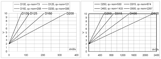
The actual measured airflow rate (qv) can be defined by the controller feedback signal (U or U5) and airflow controller nominal airflow (qv_nom).
| SIGNAL | FORMULA | CONTROLLER TYPE AND MODE |
TERMINALS SYSTEM NEUTRAL |
TERMINALS SIGNAL |
| 0…10 VDC |
qv = qv_nom * U/10 | HFD;CU=EE (NMV-D2-MP), mode 0…10 V HFD;CU=EG (GLB181.1E/3) |
1 (GND)
2(G0) |
5 (U5)
9 (U) |
| 2…10 VDC |
qv = qv_nom * (U-2)/8 | HFD;CU=EE (NMV-D2-MP), mode 2…10 V HFD;CU=ED (VRD2+NM24-V) |
1 (GND)
1 (GND) |
5 (U5)
5 (U5) |
The actual airflow rate can also be determined from the pictures below.
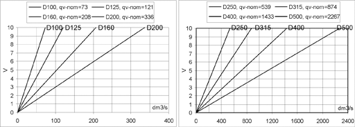
The actual airflow rate can be calculated as a function of differential pressure at the measurement probe and the measurement probe k factor. The proper k factor can be found in an attachment for the product.
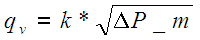
qv actual airflow rate [l/s]
k k value of the product
dP_m differential pressure of measurement probe [Pa]
The EE and ED airflow controllers are equipped with a dynamic pressure differential sensor, and there is a low airflow rate through the pressure sensor. Therefore, a manual manometer cannot be connected in parallel with the airflow controller for differential pressure measurement. If a manometer will be used, the airflow controller power supply shall be switched off in order to stop damper movement during measurement of airflow probe differential pressure. Note that the duct pressure might vary during the measurement.
The EG airflow controller is equipped with a static membrane pressure sensor including automatic zero point calibration, and there is no airflow through the differential pressure sensor of the controller. Therefore, a manual differential measurement manometer can be connected in parallel to the airflow controller (for example with tube T-branches) and both measurements can operate in parallel with continuous control.
Specification
SUGGESTED SPECIFICATIONS
The dual duct mixing unit shall be made of galvanised steel with airflow measurement probes of aluminium.
Duct connections D = 100…500 mm shall include airtight neoprene or EPDM rubber gaskets. Damper blades shall include rubber gaskets.
The dual duct unit shall comprise airflow measurements, flow controllers and damper actuators. Design airflow range limits shall be calibrated at the factory.
The casing shall be acoustically insulated with 25-mm-thick mineral wool to avoid airborne noise emission into the duct and radiation of noise through the damper casing. When specified, unit design shall have additional external insulation containing 40 mm of acoustic material and a galvanised steel cover applied over the standard casing.
The dual duct unit shall be equipped with a sound attenuator in order to meet the sound level requirement for the room. As an option, the sound attenuator shall contain a central baffle.
Downloads
"*" indicates required fields
ABD – Automatic balancing damper for kitchen ventilation (ETL)
product
ABD – Registre d’équilibrage pour la ventilation des cuisines (CE)
product
Halton BOX – Boîte de détente à débit d’air variable (VAV)
product
Halton HFD – Boîte de détente et de mélange
product
Halton Max MLC – Régulateur à débit d’air variable (VAV)
product
Halton Max MOC – Régulateur à débit d’air variable (VAV)
product
Halton Max MOS – Régulateur à débit d’air variable (VAV)
product
Halton Max MSB – Boîte de détente VAV compacte
product
Halton PRA – Régulateur à débit variable
product
Halton PTS – Registre de réglage étanche
product
Halton RMC – Régulateur CAV
product
Halton UKV – Régulateur à débit variable
product
Halton UTK – Registre de réglage à lames opposées (CAV)
product
Halton UTT – Registre de réglage étanche à lames opposées (CAV)
product
UTA – Registre d’arrêt et d’équilibrage du débit d’air
product
UTG – Gastight shut-off damper
product
UTP – Registre d’équilibrage
product