Product / KFM
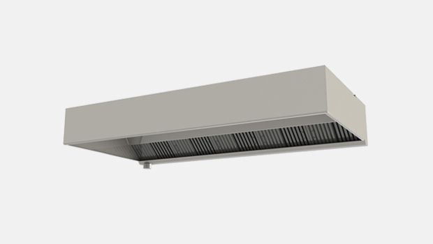
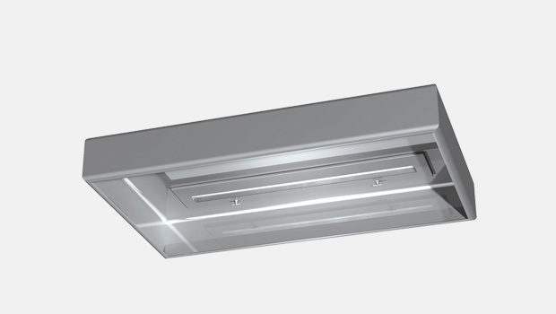
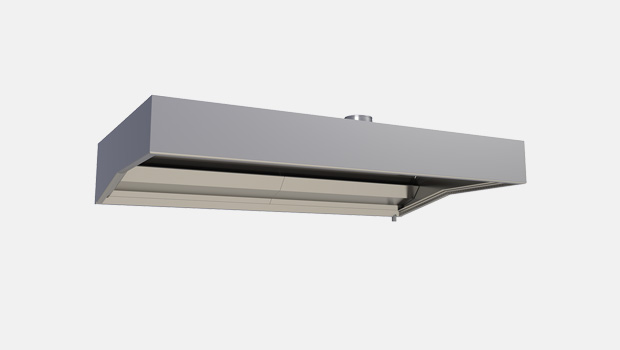
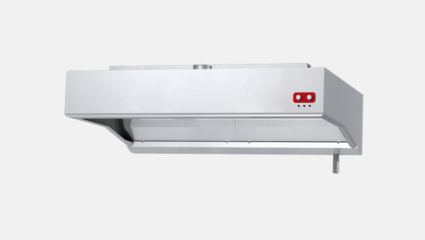
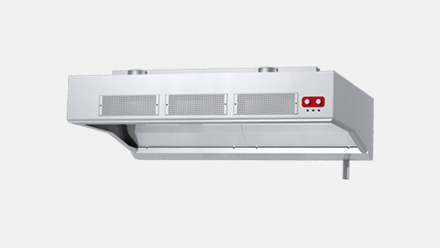
KFM – Galley grease hood
Halton KFM is a galley grease hood for use in marine & offshore applications to remove contaminated air released by cooking equipment with low heat loads.
Features
- The design follows USPHS guidelines
- Easily removable filters for cleaning
- High level of hygiene facilitated
- Prevention of the build-up of grease deposits, which pose a serious fire hazard
- With Halton Capture JetTM technology reducing the required exhaust airflow rate and improving the capture and containment efficiencies of the hood, while reducing energy use
- High-efficiency grease filtration using Halton KSA multi-cyclone filters
- Supplied as standard with lighting, balancing dampers for both capture and exhaust air and T.A.B.™ airflow measurement taps, which allow accurate and effective balancing of airflows, and efficient commissioning
- Stainless steel welded construction
- High-efficiency grease filtration using Halton KSA multi-cyclone filters
Specification
Halton KFM is a galley grease hood for use in marine & offshore applications to remove contaminated air released by cooking equipment. The KFM hood uses Halton Capture Jet™ technology, which allows the hood to operate with up to 30% lower exhaust airflow rates than traditional hoods.
Dimensions
KFM general drawings
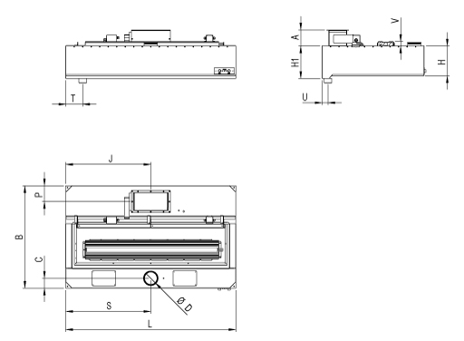
| KFM DIMENSIONS (mm) | |
| A | 195 |
| B | 1100-1900 |
| C | 115 |
| D | 100-200 |
| H | 350 |
| H1 | 380 |
| J | 1/2L |
| L | 1000-3000 |
| P | 185 |
| S | 1/2L |
| T | 200 |
| U | 70 |
| V | Max 50 |
Note: Maintenance / light fixture hatch is as big as the construction allows.
Material
| PART | MATERIAL | THICKNESS | NOTE |
| Main body | Stainless steel EN 1.4301 (AISI304) | 1,25 mm | Option: EN 1.4404 (AISI316L) |
| Light fixture | Painted steel | – | – |
| Cables | Halogen free | – | – |
Construction
The KFM hood comprises a Capture Jet™ air supply module, a light fixture, adjustment dampers, airflow measurement taps and KSA grease filters. All parts of the hood are manufactured from polished stainless steel EN 1.4301 (AISI304). The Capture Jet™ supply plenum is thermally insulated through the use of mineral wool material to prevent condensation on the inner face above the cooking equipment. The hood is equipped with removable grease cup for collection of the grease.
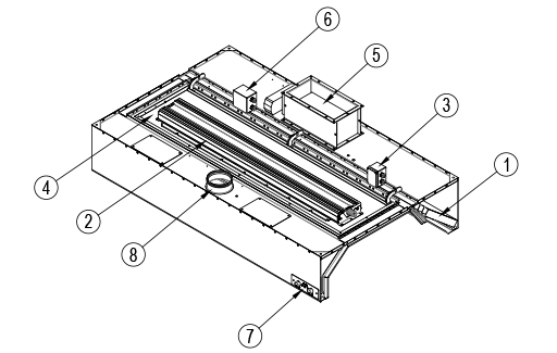
PARTS
- KSA grease filters
- Lighting fixture
- Lighting fixture power supply junction box
- Maintenance hatch
- Exhaust air connection, fire damper or shut-off damper* (available as an option) and adjustment damper
- Fire damper junction box (available as an option)
- Damper switch and indication (available as an option)
- Capture air connection and adjustment damper
*If fire or shut-off damper is located at the duct, Halton suggests two default solutions for duct connection:
- Eurovent-collar with flange
- Welded L-collar
Eurovent-collar with flange
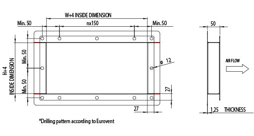
Welded L-collar

Weights of standard KFM hoods (kg)
| B/L | 1000 | 1500 | 2000 | 2500 | 3000 |
| 1100 | 40 | 60 | 80 | 100 | 110 |
| 1300 | 46 | 66 | 86 | 106 | 118 |
| 1500 | 51 | 71 | 92 | 111 | 126 |
| 1700 | 57 | 77 | 98 | 117 | 134 |
| 1900 | 63 | 83 | 103 | 123 | 142 |
The above table represents an indication of different size of average KFM hoods without Capture Jet technology. Weight does not include the fire damper.
Weights of standard KFM hoods with Capture Jet Technology (kg)
| B/L | 1000 | 1500 | 2000 | 2500 | 3000 |
| 1100 | 50 | 74 | 100 | 124 | 138 |
| 1300 | 56 | 80 | 105 | 129 | 146 |
| 1500 | 61 | 86 | 111 | 135 | 154 |
| 1700 | 67 | 92 | 117 | 141 | 162 |
| 1900 | 73 | 97 | 122 | 147 | 170 |
The above table represents an indication of different size of average KFM hoods with Capture Jet technology. Weight does not include fire damper.
Function
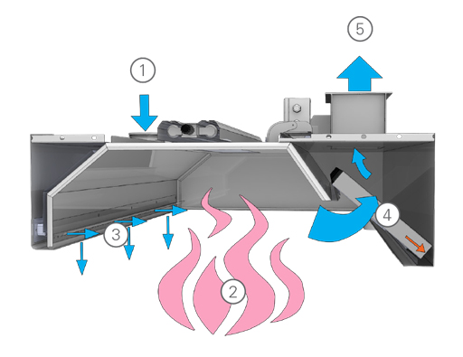
- Supply air enters the Capture JetTM plenum.
- Contaminated air and heat rises from the cooking appliances.
- Contaminated air is directed into the hood by Halton patented Capture JetTM technology.
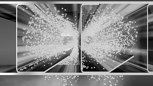
- KSA multi-cyclone filters remove grease and contaminants from the air stream with the aid of centrifugal effect. According to independent laboratory tests KSA is the most efficient mechanical grease filter on the market.
- Filtered exhaust air.
Recommended exhaust airflow for KFM
| RECOMMENDED EXHAUST AIRFLOW | ||||
| NUMBER OF KSA FILTERS | MINIMUM l/s | MAXIMUM l/s | MINIMUM m3/h | MAXIMUM m3/h |
| 1 | 130 | 201 | 468 | 724 |
| 2 | 259 | 402 | 932 | 1447 |
| 3 | 389 | 602 | 1400 | 2167 |
| 4 | 518 | 803 | 1865 | 2891 |
| 5 | 648 | 1004 | 2333 | 3614 |
| 6 | 778 | 1205 | 2801 | 4338 |
Note: KSA filter size 500x330x50 mm
Specifications
Suggested specification
General
The galley hoods shall be constructed from stainless steel EN 1.4301 (AISI304). The galley hoods shall be supplied complete with outer casing / main body, airflow measurement taps, exhaust air spigot connection with adjustment damper, maintenance hatch, light fixture, grease filters, grease cup. Classified fire damper in each exhaust connection. Classified fire damper in each exhaust connection is available as an option. he manufacture of all galley hoods shall be controlled by ISO 3834-2:2005, ISO 9001, 14001 and OHSAS 18001 standards. The design of hoods shall follow USPHS guidelines.
Construction
All parts shall be constructed of stainless steel sheet (thickness 1.25 mm) with a polished finish. The inside corners of the hood are rounded for easy cleanability according to USPHS guidelines. The joints at the lower edges of the device are welded. All visible screws are thumb screw type. The hood is equipped with a grease cup for removing the grease. There is a maintenance hatch in each hood for easy access above the hood.
Capture Jet plenum
The Capture JetTM plenum shall be insulated with sealed mineral wool. Plenum can be accessed through a maintenance hatch(es).
Capture Jet system
The hood shall be designed with Capture JetTM technology to reduce the exhaust airflow rate required and increase the capture and containment efficiencies of the hood, while reducing energy use.
Airflow measurement taps
Measurement taps shall be located on top of the hood for supply air and exhaust air measurement.
Halton KSA filter
- Minimisation of grease deposits in the ducts
- Enhanced hygiene and safety
The KSA grease filters shall be constructed of stainless steel. The grease filters shall be supplied in modular size of 500x330x50 mm and shall be removable via two folding handles. The grease filters shall have a honeycomb design in order to allow high grease filtration efficiency with the aid of centrifugal effect in filter honeycombs.
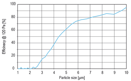
Mechanical filtration is recommended to be used in hoods with low utilization rate and cooking process producing mainly large grease particles (> 8 microns), e.g. food prepared with gas fryers, griddles and broilers (source ASHRAE).
Duct connections
The duct connections and adjustment dampers for exhaust air shall be constructed from stainless steel. The dampers shall be adjustable.
Light fixtures
Each hood shall be delivered with LED light fixtures providing approx. an average illuminance of 500 lux at the work surfaces of the cooking appliances. The light fixtures shall be suitable for a single-phase 230-VAC power supply and shall be manufactured to be of protection class IP67. The driver shall be located within the light frame. The core electric cables connecting the light fixture to the junction box shall be provided. The light fixture shall be installed on a hinged maintenance hatch, allowing access to the hood roof.
LED light fixture sizes
| HOOD DIMENSION | LENGTH | WIDTH |
| L < 1250 mm, 1×28 W | 720 mm | 175 mm |
| L > 1250 mm, < 2000 mm, 1×42 W | 1020 mm | 175 mm |
| L > 2000 mm, 1×69 W | 1620 mm | 175 mm |
Maintenance hatch
Each hood shall be provided with a maintenance hatch made of stainless steel with a shock- resistant plastic window. The heat tolerance of the window shall be up to +115 °C. The hatch shall be easily opened and closed. The maintenance / light fixture hatch is as big as the construction allows.
Airflow measurement
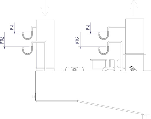
∆Pst = Static pressure loss
∆PTAB = TAB pressure for airflow rate measurement
Product code
(S)=Model
(N) With Capture Jet
(S) Without Capture Jet
(L)=Length
1000-3000
(W)=Width
S=N: 1000-2000 S=S: 850-2000
Model S=N with Capture Jet
Model S=S without Capture Jet
(H)=Height of front end
350 mm
(MV)=Marvel
(N) No
(A) 1 sensor
(B) 2 sensors
(C) 3 sensors
(D) 4 sensors
(UB)=UV or MARVEL Box
(C) Marvel-box PL
(N) No
(MA)=Material
(SS) Stainless steel EN1.4301
(AS) Stainless steel EN1.4404
(DS)=Diameter of supply connection
100
125
160
180
200
(LF)=Light fixture
(A) Type SLR
(B) Type LED SLV
(FK)=Fire suppression system
(N) No
(1) 1 pc
(2) 2 pcs
(3) 3 pcs
(AC)=Accessories
(BL) Capture Jet fan with potentiometer
(HE) Ceiling condensation removal heating
Code example
KFM1/N-3000-2000-350,MV=N,UB=N,MA=SS,DS=100,LF=A,FK=1,ZT=Y,AC=BL
Downloads
"*" indicates required fields
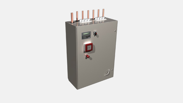
CCW-M – Control cabinet
product
KFM – Galley grease hood
product
KVM – Extraction canopy
product
KW3 – Hotte de cuisine Water Wash pour navires
product
KWH – Hotte de cuisine Water Wash pour navires
product
KWT – Galley water wash hood with supply air
product
WR – Water wash control cabinet
product