Product / CFD02
CFD -02TM – Korkean lämpötilan ilmavirtasäädin tunneliin
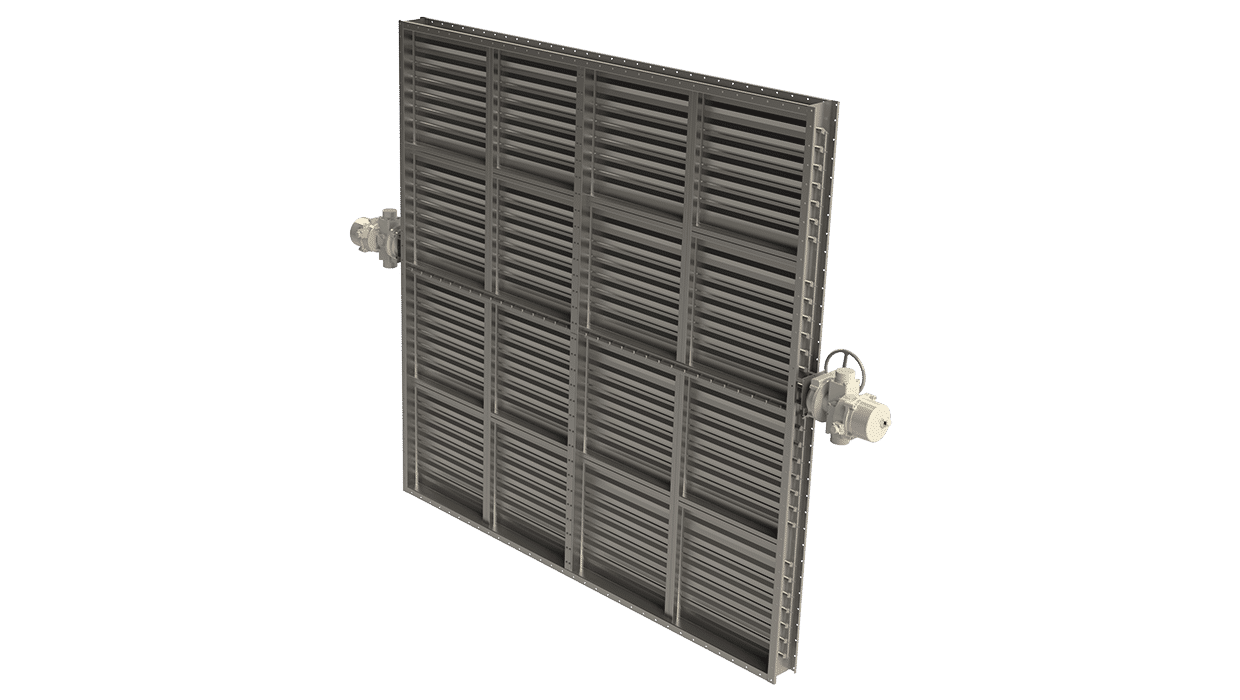
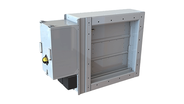
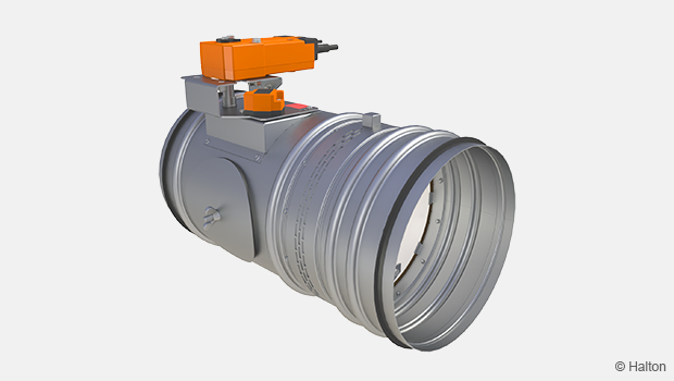
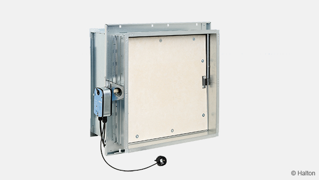
The type CFD-02TM High temperature tunnel damper has been designed for bolting / clamping directly onto walls and floors or bolting to steel support frames / ductwork.
Overview
- Has been successfully tested for operation in temperatures of 400°C for 2 hours
- The design has been proven to withstand, with blades closed, repetitive loading of 6000 Pascals due to pressure transients, 7.8 million cycles
- The damper has been Fire Endurance tested in accordance with UL555 and BS476 PT20 for 2 hours
- Blade Deflection tested at 4000Pa at 400 C for 1 hour
- 100,000 cycle tested (automatic operation) – endurance tested
- UL Damper Hose Stream tested after Fire test in accordance with ASTM E2226 15b
- Independently Low Demand SIL 4 rated
Specification
Flamgard Calidair’s tunnel dampers are rigidly designed and are used to regulate the airflow in transit tunnels. They ensure that the air that is circulating through the tunnel is safe for passenger transit, without excessive build-up of exhaust gases. In normal conditions, tunnel dampers control the volumetric air flow in a transit tunnel.
In emergency fire conditions, it is essential that the dampers are there not only for ventilation, but to regulate the fire and the associated smoke and hot gases. Fires in tunnels generate severe smoke which, if not reliably ventilated, could cause those in the tunnel to suffer the life-threatening effects of smoke inhalation. Tunnel dampers can be used in emergency conditions to operate to extract these toxic fumes and smoke away from the critical area as well as providing a fire barrier when closed
Highly customisable controls configurations to enable optimised damper free area to ensure best use of tight site conditions, improving air flow and minimising pressure drop. Actuator locations can also be modified to achieve best accessibility for easy of commissioning and maintenance.
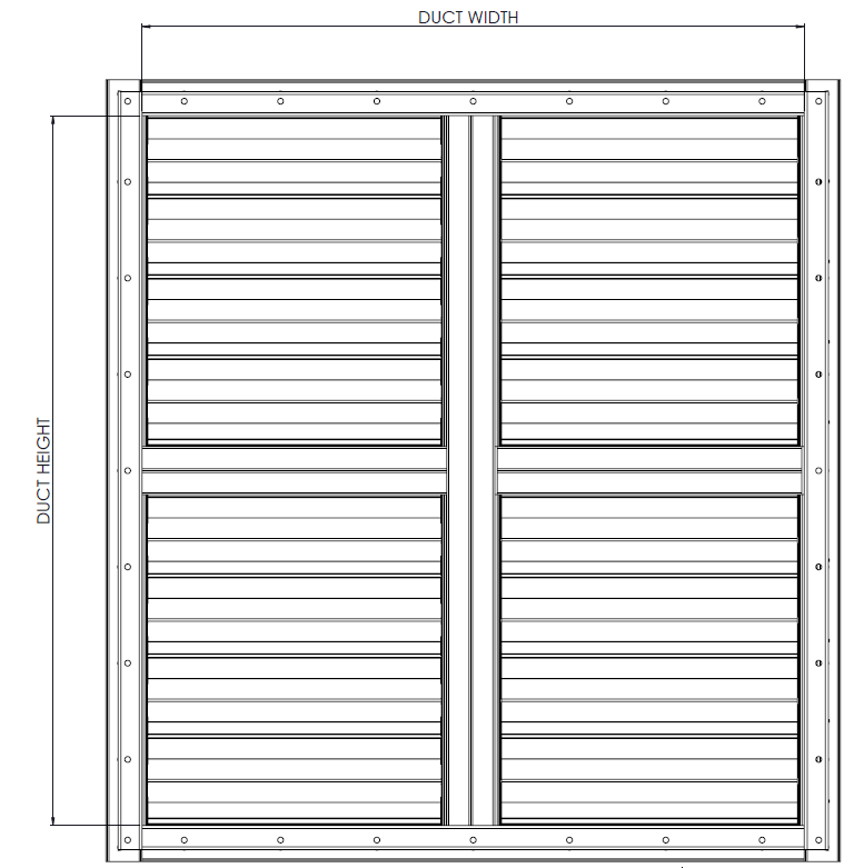
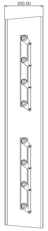
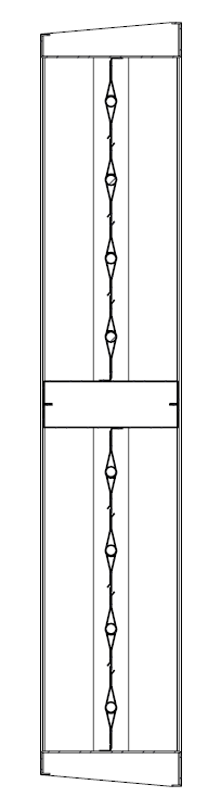
Dimensions
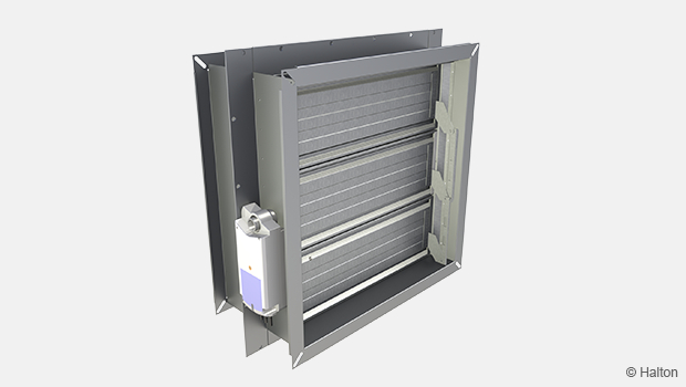
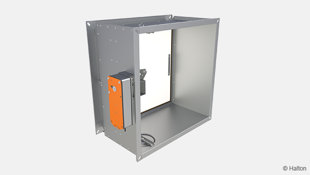
Casing
The damper casing is formed from 3.0 mm thick sheet steel into a rigid channel section to ensure proper alignment of blades and shafts. Damper units in excess of 2550mm width or 1900mm height shall be manufactured as a multiple assembly. Damper insertion depth is 300mm.
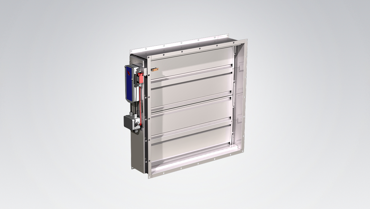
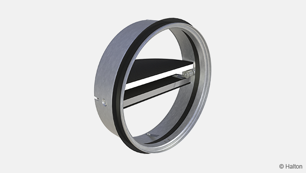
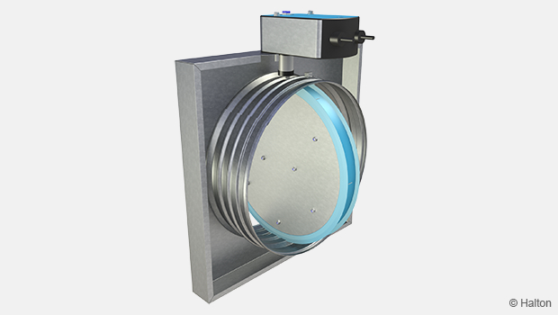
Blades
The blades are a formed double-skin aerofoil section of 2.0 mm sheet metal. Blade stops at the top and bottom of the casing and sprung side seals provide excellent low leakage characteristics. As an option, the blade ends can be capped and fitted with blade edge seals.
Shafts
Continuous shafts are Ø 20mm. The blades are plug welded at each end.
Linkage
Parallel action linkage consisting of drive levers connected by flat bar link bars, driven through stainless steel pins. All linkage is contained within the depth of the damper casing.
Bearings
Phosphor bronze self-lubricated ‘Oilite’ flanged bushes.
CFD-02TM General Drawings
Material and Finishing
| Part | Material | Finishing |
| Case | Mild Steel | Painted or Galvanised |
| Case | Stainless Steel – 1.4307 (304L) Stainless Steel – 1.4404 (316L) |
– |
| Blades | Mild Steel | Galvanised |
| Blades | Stainless Steel – 1.4307 (304L) Stainless Steel – 1.4404 (316L) |
– |
| Shafts | Stainless Steel – 1.4307 (304L) Stainless Steel – 1.4404 (316L) |
– |
| Bearings | Phosphor Bronze ‘Oilite’ (Self Lubricating) | – |
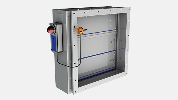
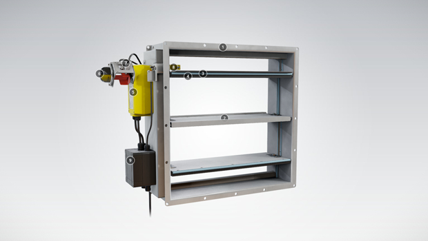
Product Models and Accessories
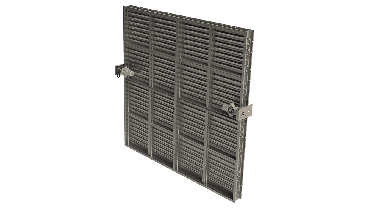
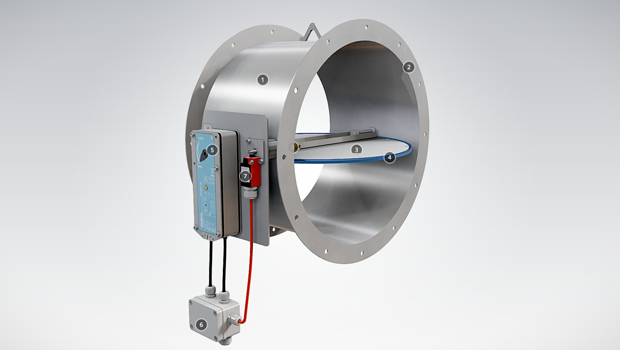
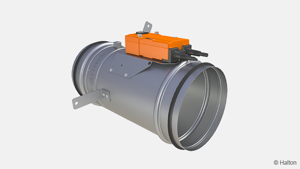
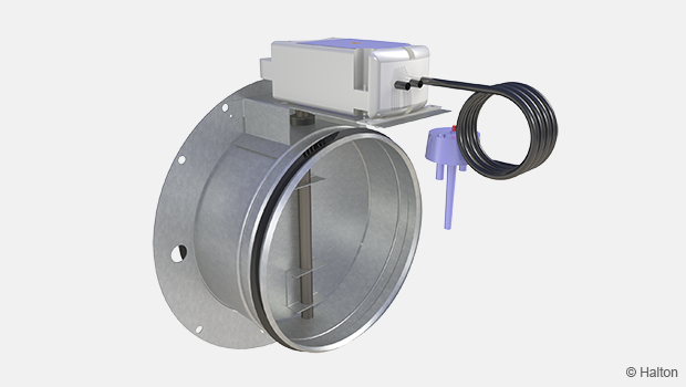
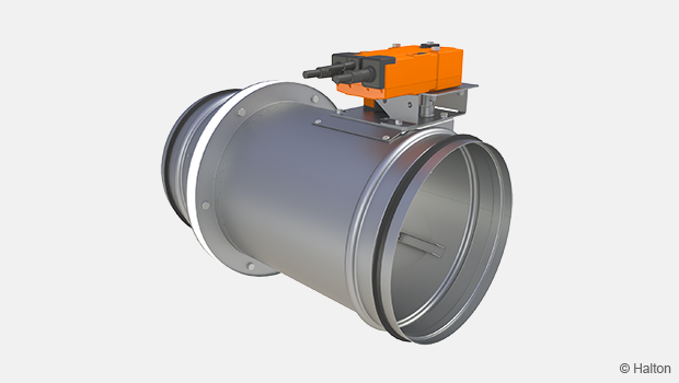
- Damper can be supplied with either a pneumatic or electric actuator depending on requirements
- The damper frame can be supplied with lifting eyes in each vertical side channel. These are provided for lifting the unit safely and without damage
- Actuators can be offset from the damper using a “pantograph” arrangement
- Thermal jacket can be supplied to protect the actuator from high a temperature environment.
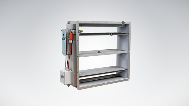
Operation Principle
The CFD-02TM dampers utilize a parallel or opposed linkage system to open and close the damper units and can be normally open or normally closed depending upon the requirement. The airflow through the Flamgard Calidair damper is bi-directional and the orientation can be vertical or horizontal.
Weights
Weights for specific sizes are issued on the quotation documents.
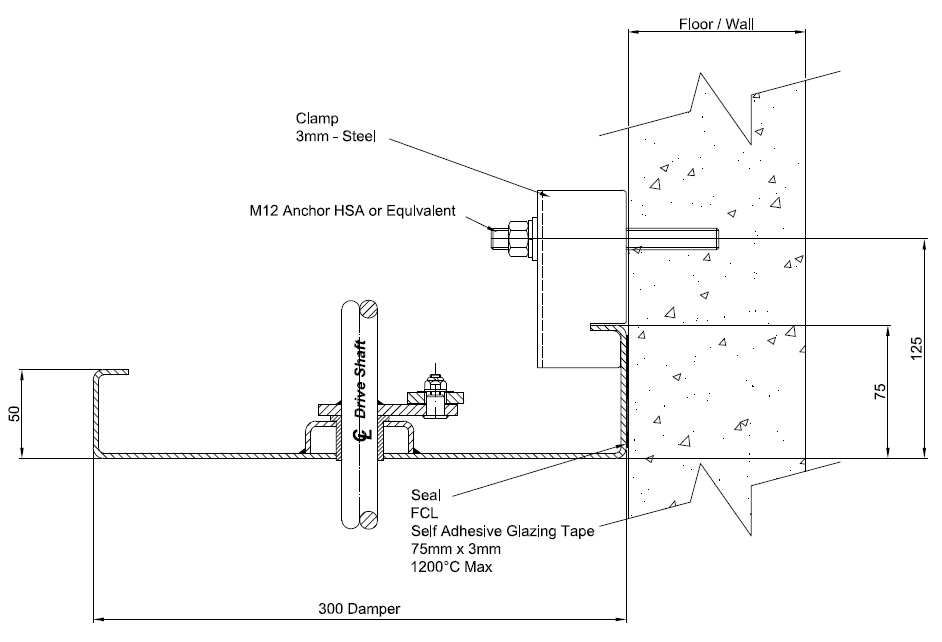
Installation
- Suitable clamps and wall anchors should be used to support the damper to the concrete surface.
- The wall anchors (bolts) and wall clamps are to be suitable to support the weight of the damper and for the mounting surface. They should also be suitable for the site conditions and location and design limits for high temperature applications. As a guide, wall clamps and anchors are to be at 200mm spacing around the damper mounting flange. The wall anchor bolts are to be installed as per manufacturers guidelines and set at the correct distance from the concrete opening.
- When mounting to a concrete surface, dampers cannot be ‘hung’ from the ceiling. For vertical or horizontal mounting to concrete surfaces.
- Gasket, suitable for the high temperature and leakage requirements, should be installed between the mounting surface and the damper to provide a seal.
- The joining plates to join modular dampers are supplied for direct mounting to the flanges of the damper. These can be sealed after damper assembly using suitable fire rated sealant to enhance the leakage performance.
- If the actuators are off-set from the damper, on a pantograph arrangement, an angle bracket is fitted to allow clamping of the pantograph to the wall/floor and to add support for the off-set weight of the actuator.
- The damper flanges are extended on each corner of damper assembly to provide a direct fixation of the damper at each corner to the wall. This provides additional support and also aids with installation.
Downloads
Request for Quotation
"*" indicates required fields
CFD -02TM – Korkean lämpötilan ilmavirtasäädin tunneliin
product
FCE Palopelti (EI 60 S)
product

FDA – A0(60) Kaasutiivis palopelti
product
FDB2 A0(A60) Kaasutiivis palopelti
product
FDH – H0(H120) Kaasutiivis palopelti
product
FDK – A0(A60) Fire damper
product
FDL – A0(A60) Palopelti
product
FDO A0(A60) Kaasutiivis palopelti
product
Halton Exe EDC – Palopelti (EI 120 S)
product
Halton Exe EFC – Palopelti (EI 120 S)
product
Halton Exe ELC – Palopelti (E 120 S)
product
Halton Exe ELR – Palopelti (E 120 S)
product
Halton Exe ESC – Palopelti (EI 120 S)
product
Halton Exe ESR – Palopelti (EI 120 S)
product
Halton Exe ETC – Palopelti (EI 120 S)
product

Halton Exe ETR – Palopelti (EI 120 S)
product
Halton FDI – Palopelti (EI 60 S)
product

Halton FDS – Palopelti (E 60)
product
Halton FDT – Palopelti (EI 60 S)
product
Halton FDV – Palorajotinventtiili (E 120 S)
product