Product / FDL
FDL – A0(A60) Palopelti
Halton FDL fire dampers are type-approved class A0(A60) fire dampers.


Overview
IMPORTANT TO NOTE:
Important information to Halton Marine, Energy and Infrastructure customers
We hereby inform you that we have decided to discontinue the manufacturing of the FDL fire dampers gradually.
Kindly note that a valid type approval certificate is required when product has been installed on board a ship. Certificates for FDL fire dampers are valid as follows:
- MED (BV), expires 26.1.2026
- Lloyd’s Register, expires 20.7.2025
- DNV, expires 7.2.2026
- ABS, expires 2.9.2026
************************
Type-approved by most recognized classification societies: class A0 without insulation, A15-A60 when suitably insulated
Shock and vibration tested
Blades with intumescent seals
A closed damper fulfils the requirement of leakage class (EN1751:2014) from class 1 to class 2 depending on the size. Details are available from Halton Marine
Casing leakage (EN1751:2014) class B
The nominal fuse release temperatures are 50 ºC, 74 ºC or 100 ºC. Other temperatures are available
Can be installed in any position
Automatic electrical, pneumatic or spring operation system available
Maximum duct pressure for damper construction 5000 Pa and maximum air velocity 15 m/s
Normal operation temperature for damper between -50 ºC to +80 ºC. Actuator and component selection can affect this temperature range. Other temperatures available on request
Available as ATEX/IECEx approved
SIL 2 safety assessment certificate available for the damper on specific terms
Specification
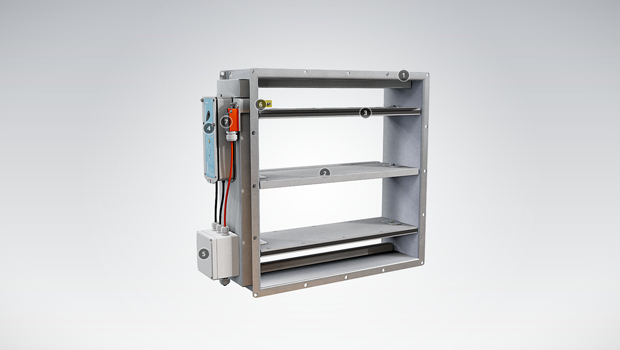
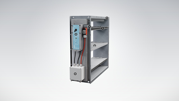
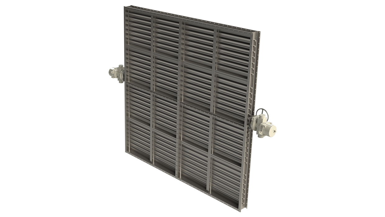
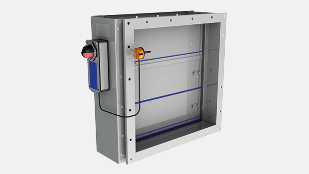
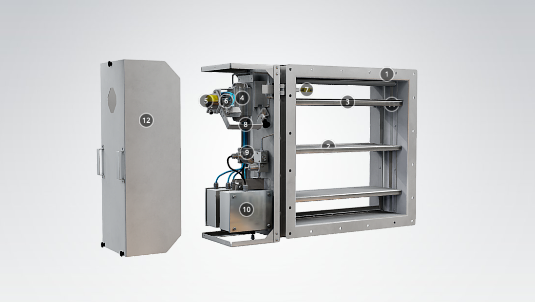
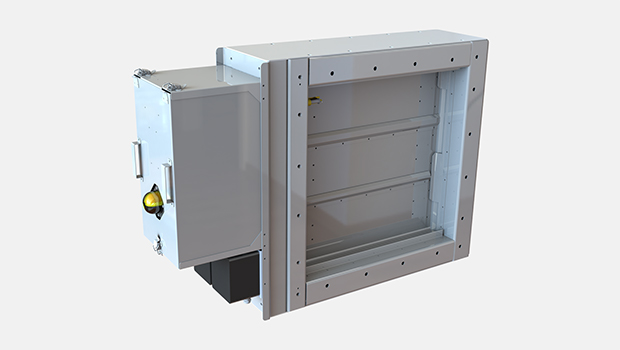
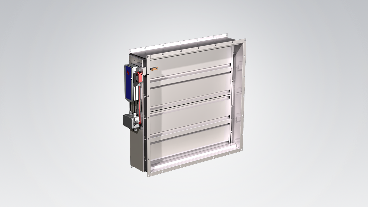
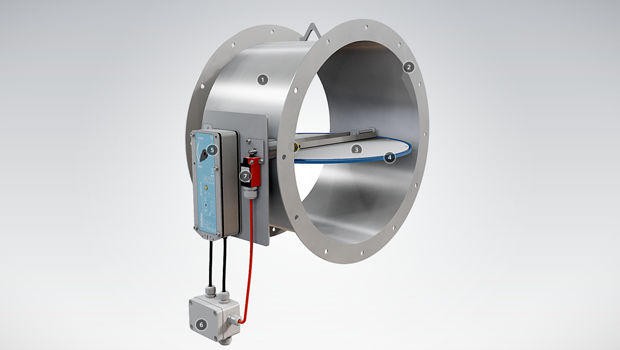
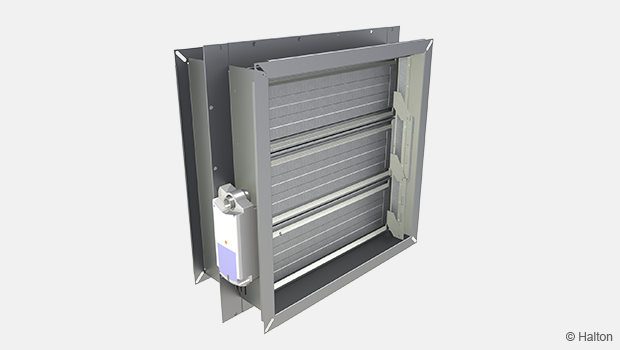
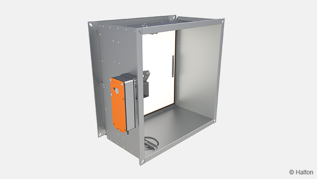
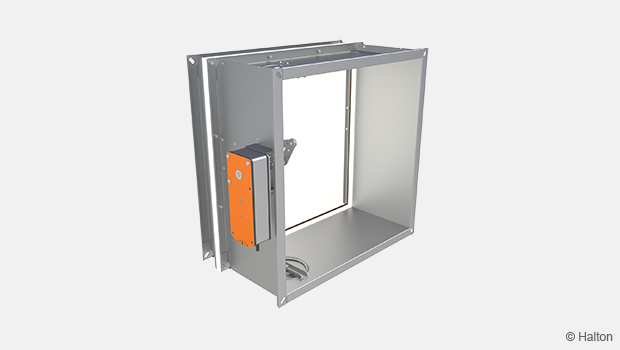
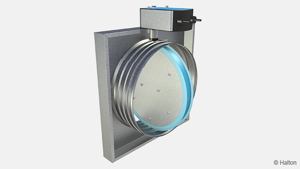
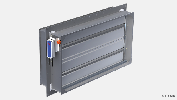
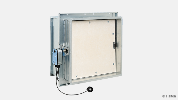
Halton FDL fire dampers are type-approved classA0(A60) fire dampers for use in offshore, marine and navy ventilation systems. The FDL can be installed in rectangular or circular ducts. The FDL dampers are used to prevent the spread of fire within the ventilation ductwork. All fire dampers have a fusible link and spring return actuator. When the blades are in the open position, the device does not cause significant pressure loss or flow disturbance. Fire dampers are set from outside and can be installed in any position. An open-closed indicator is visible on the outside of the damper. Fire dampers with non-standard dimensions can also be supplied on request.
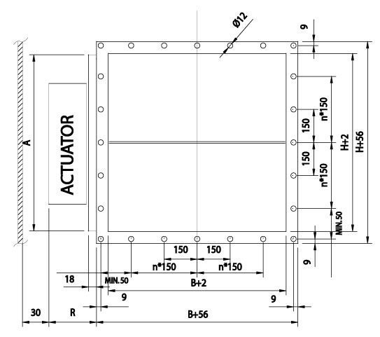
Dimensions
The Halton FDL fire dampers are manufactured according to international standards for both rectangular (width B 100-1300 mm and height H 100-1200 mm, 1 mm division) and circular ducts (Ø100-1250 mm). Modular constructions are available for bigger sizes. Non-standard dimensions and flange drilling are available on request.
Standard flange width 27 mm. Flanges and drilling also available according to ISO 15138 standards.
Blades are made of two sheets, each of them being 1 mm thick (sandwich design).
Modular construction sizes up to 2660×2460 mm.
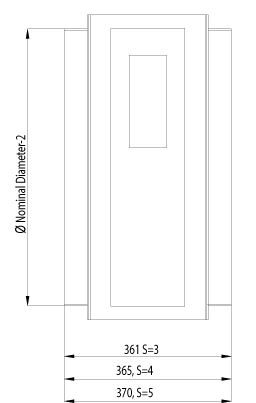
Frame material thickness 3 mm or 3-5 mm according to SOLAS.
Frame thickness according to SOLAS
| DIMENSIONS | S |
| If B or H > 100, but < 449 | 3 |
| If B or H > 450 but < 649 | 4 |
| If B or H > 650 | 5 |
Frame thickness according to SOLAS, Edition Dec. 2015
| DIMENSIONS | S |
| If A < 0.075 m2 | 3 |
| If A > 0.075 and A < 0.45 m2 | 4 |
| If A > 0.45 m2 | 5 |
Actuator effect in dimensions
| ACTUATOR | R | A | |
| Electrical (EL) | BF230, BF24, BF120 | 100 | H<300 = 300, H>300 =H |
| Pneumatic (PNR) | Pneumatic rotating actuator AT100 | 170 | H<300 = 300, H>300 =H |
| Pneumatic (PNR) | Pneumatic rotating actuator AT200 | 190 | H<350 = 350, H>350 =H |
| Spring (SP) | Spring | 140 | H |
The above table contains only some examples of actuators and their effect on dimensions.
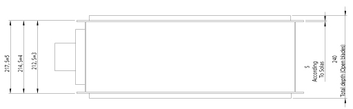
FDL, general drawings
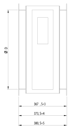
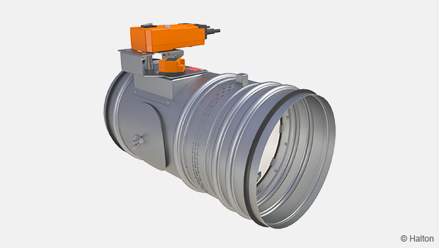
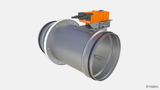
With circular connections
FDL, top
FDL circular, with connection flanges
| DAMPER HEIGHT H | TOTAL DEPTH WITH BLADES OPEN |
| < 250 mm | 212 mm |
| > 250 mm <300 mm | 250 mm |
| > 300 mm <350 mm | 212 mm |
| > 350 mm | 240mm |
Material and Finishing
| PART | MATERIAL | FINISHING |
| Frame | Carbon steel | Painted or galvanized |
| Frame | Stainless steel EN 1.4301 (AISI304), EN 1.4404 (AISI316L), EN 1.4432 (AISI316L) | – |
| Blades | Steel | Galvanized |
| Blades | Stainless steel EN 1.4301 (AISI304), EN 1.4404 (AISI316L), EN 1.4432 (AISI316L) | – |
| Maintenance-free bearings |
Stainless steel EN 1.4404 (AISI316L) | – |
| Shafts | Stainless steel EN 1.4404 (AISI316L) | – |
Standard frame material thickness 3-5 mm according to SOLAS.
Product Models and Accessories
Halton FDL is available with following actuators:
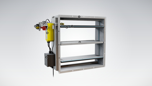
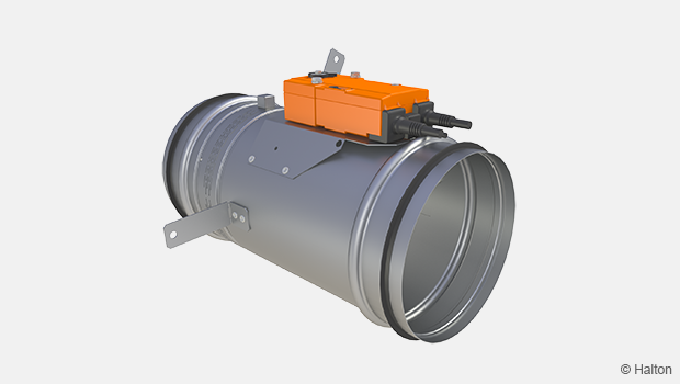
- FDL-EL: Electrical spring return motor; standard actuators being 24 V or 230 V or 120 V. The motor contains built-in open-closed limit switches. Separate junction box included in the EL-model. A wide range of Ex actuators available, including a one second closing time function as an option.
- FDL-PNR: Pneumatic rotating actuator.
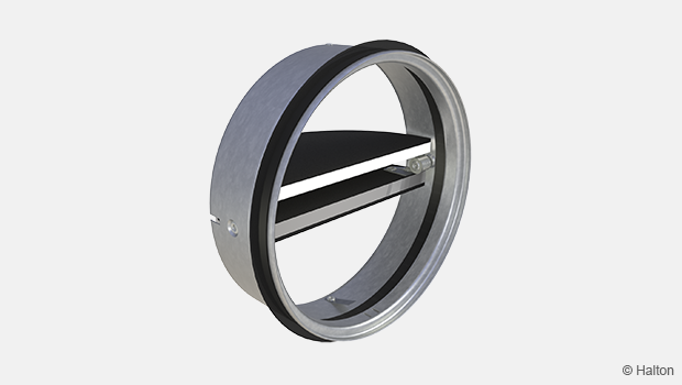
- FDL-SP: Manual spring-actuated damper with fusible link.
DOT: manual override function available for PNR and EL models.
HSO: Halton Smart Override function for HVAC damper black-start available for PNR and EL models. With automatic reset function when power and/or pneumatic air supply is reinstated.
A wide range of accessories available.
Operation Principles
In the event of a temperature rise in ductwork:
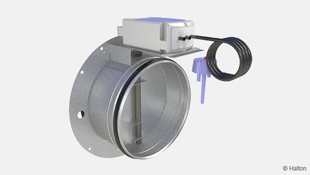
- FDL-EL: fusible link releases and cuts off operating voltage to the spring return motor, allowing the spring to close the damper blades. The fire damper opens automatically when the fuse has been changed and the operating voltage to the motor is re-established.
- FDL-PNR: fusible link releases and cuts off operating pressure to the spring return actuator, allowing springs to close the damper blades. The fire damper opens automatically when the fuse has been changed and the pneumatic air supply is re-established.
- FDL-SP: fusible link releases allowing the spring to close the damper blades. When the fuse has been changed, the fire damper must be reset into open position manually.
Weights
Weight of standard Halton Marine FDL dampers without an actuator (kg)
| H/HEIGHT (mm) |
B / WIDTH (mm) | ||||||||||||
| 100 | 200 | 300 | 400 | 500 | 600 | 700 | 800 | 900 | 1000 | 1100 | 1200 | 1300 | |
| 100 | 5 (5) | 7 (7) | 9 (9) | 10 (10) | 12 (13) | 14 (15) | 15 (22) | 17 (25) | 19 (27) | 20 (30) | 22 (32) | 24 (35) | 25 (37) |
| 200 | 7 (7) | 9 (9) | 11 (11) | 12 (12) | 14 (16) | 16 (18) | 18 (26) | 20 (28) | 22 (31) | 23 (34) | 25 (36) | 27 (39) | 29 (41) |
| 300 | 9 (9) | 11 (11) | 13 (13) | 15 (15) | 17 (19) | 19 (21) | 21 (30) | 23 (32) | 25 (35) | 27 (38) | 29 (41) | 31 (43) | 33 (46) |
| 400 | 11 (11) | 13 (13) | 15 (15) | 17 (17) | 20 (22) | 22 (24) | 24 (33) | 26 (36) | 28 (39) | 30 (42) | 32 (45) | 34 (48) | 37 (51) |
| 500 | 13 (16) | 16 (19) | 18 (22) | 21 (25) | 23 (27) | 25 (30) | 28 (38) | 30 (41) | 32 (44) | 35 (47) | 37 (50) | 39 (54) | 42 (57) |
| 600 | 15 (18) | 18 (21) | 20 (24) | 23 (27) | 25 (30) | 28 (33) | 30 (41) | 33 (45) | 35 (48) | 38 (51) | 40 (55) | 43 (58) | 46 (61) |
| 700 | 18 (25) | 21 (28) | 23 (32) | 26 (35) | 29 (39) | 32 (42) | 34 (46) | 37 (50) | 40 (53) | 42 (57) | 45 (60) | 48 (64) | 51 (67) |
| 800 | 20 (27) | 23 (31) | 25 (35) | 28 (38) | 31 (42) | 34 (46) | 37 (50) | 40 (53) | 43 (57) | 46 (61) | 49 (64) | 51 (68) | 54 (72) |
| 900 | 22 (31) | 25 (35) | 28 (39) | 32 (42) | 35 (46) | 38 (50) | 41 (54) | 44 (58) | 47 (62) | 50 (66) | 53 (70) | 56 (74) | 59 (78) |
| 1000 | 24 (33) | 27 (37) | 31 (41) | 34 (45) | 37 (50) | 40 (54) | 44 (58) | 47 (62) | 50 (66) | 53 (70) | 57 (74) | 60 (78) | 63 (82) |
| 1100 | 26 (36) | 30 (41) | 33 (45) | 37 (49) | 40 (54) | 44 (58) | 47 (62) | 51 (67) | 54 (71) | 58 (75) | 61 (79) | 65 (84) | 68 (88) |
| 1200 | 28 (39) | 32 (44) | 36 (48) | 39 (52) | 43 (57) | 46 (61) | 50 (66) | 54 (70) | 57 (75) | 61 (79) | 65 (84) | 68 (88) | 72 (92) |
| D2 ØD | WEIGHT |
| (mm) | kg |
| 100 | 8 (8) |
| 125 | 8 (8) |
| 160 | 12 (12) |
| 200 | 13 (13) |
| 250 | 19 (19) |
| 315 | 20 (20) |
| 400 | 27 (27) |
| 500 | 35 (43) |
| 630 | 46 (62) |
| 800 | 62 (89) |
| 1000 | 83 (118) |
| 1250 | 113 (162) |
(Frame thickness according to SOLAS)
Examples of actuator weights: FDL-EL BF230 +3,2 kg, BFN +1,4 kg, ExMax /Redmax +3,5 kg, CSQP +3 kg. FDL-PNR AT100 +2,1 kg, AT100 as AISI316 4,4 kg, AT200 +3,2kg, AT200 as AISI316 +6,2 kg, FDL-SP +1 kg. Control enclosure +4 kg.
Installation
Installation and maintenance instructions are with each fire damper delivery. Copies of Operation and Maintenance manuals are available from Halton Marine Sales offices and distributors.
Product Code
(S)=Shape of Connection
(A) Circular (D1)
(C ) Circular (D2)
(R) Rectangular
(W)=Width
100-1300
(H)=Height
100-1200
(D)=Diameter
100-1250
(FA)=Fire Approval
(C1) ABS American Bureau of Shipping
(C2) MED Marine Equipment Directive
(C4) DNV Det Norske Veritas
(C5) BV Bureau Veritas
(C6) GL Germanischer Lloyds
(C7) USCG United States Cost Guard
(C9) RMRS Russian Maritime Register
(SF)=Flange Option
(H0) Connection flange in circular connections
(H1) Connection + loose flange in circular connections
(HA) Flanges (2 sides)
(HB) Counter flanges (2 sides)
(HC) Counter flange (1 side)
(NA) Not Assigned (circular connection)
(FS)=Frame dimensioning
(HS) Halton Standard dimensioning
(S0) SOLAS dimensioning
(MA)=Material
(AS) Stainless steel (1.0) EN1.4404
(CS) Carbon steel (1.0)
(LS) Stainless steel (1.0) EN1.4432
(SS) Stainless steel (1.0) EN1.4301
(FM)=Frame Material
(A3) Stainless steel (3.0) EN1.4404
(A4) Stainless steel (4.0) EN1.4404
(A5) Stainless steel (5.0) EN1.4404
(C3) Carbon steel (3.0) EN1.4404
(C4) Carbon steel (4.0) EN1.4404
(C5) Carbon steel (5.0) EN1.4404
(L3) Stainless steel (3.0) EN1.4432
(L4) Stainless steel (4.0) EN1.4432
(L5) Stainless steel (5.0) EN1.4432
(S3) Stainless steel (3.0) EN1.4301
(S4) Stainless steel (4.0) EN1.4301
(S5) Stainless steel (5.0) EN1.4301
(FI)=Finishing
(HG) Hot galvanized
(NA) Not Assigned (acid treatment)
(PN) Painting
(RE)=Actuator
(E1) Electric BF24-2-HL
(E3) Electric BF230-2-HL
(E7) Electric BF120-HL
(K0) Electric BFN24.1
(K1) Electric BFN24-T.1
(K2) Electric BFN230.1
(K3) Electric BFN230-T.1
(I1) InMax 15-SF
(P0) Pneumatic – Air Torque, AT101, Aluminium
(P1) Pneumatic Lin Roder 245N
(P2) Pneumatic Lin Roder 300N
(P3) Pneumatic – Air Torque, AT104, AISI316
(Q1) Pneumatic – Air Torque, AT201, Aluminium
(Q2) Pneumatic – Air Torque, AT204, AISI316
(R2) Ex-proofed RedMax 15-SF
(S1) Spring
(T1) Electric BF24-T-2.1HL
(T3) Electric BF230-T-2.1HL
(Z2) Ex-proofed ExMax 15-SF
(Z3) Ex-proofed ExMax 5-10SF
(C1) Electric CSQP-05A1E 24V
(C2) Electric CSQP-05A2E 120/230V
(C3) Electric CSQP-10A1E 24V
(C4) Electric CSQP-10A2E 120/230V
(C5) Electric CSQP-15A1E 24V
(C6) Electric CSQP-14A2E 120/230V
(FU)=Fuse
144 °C
100 °C
95 °C
74 °C
72 °C
70 °C
65 °C
50 °C
(AC)=Accessories
(BC) Belimo Casing
(E1) Junction box IP66/67 (Plastic) (Ensto)
(E2) EX junction box IP66/T6 (GRP) (Ensto)
(E4) Connectors (FD) (Wieland & Hensel))
(L1) Limit switch 1 pcs IP66 (Plastic) (Bernstein)
(L2) Limit switch 2 pcs IP66 (Plastic) (Bernstein)
(L3) EX Limit switch 1 pcs (Plastic) (Bartec)
(L4) EX Limit switch 2 pcs (Plastic) (Bartec)
(M1) Solenoid valve 24 VDC (Aluminium) (SMC)
(M2) Solenoid valve 230 VAC (Aluminium) (SMC)
(M3) EX solenoid valve 24 VDC (Brass) (Norgren)
(M4) EX solenoid valve 230 VAC (SS) (Norgren)
(P1) Pneumatic valve manual (Aluminum) (SMC)
(S3) SN2 auxiliary switch (Belimo)
Stainless steel tubing (AISI316) ( Halton)
(ED) DOT handle (manual overdrive) (Steel) (Halton)
Code example
FD3/R-1300-1200,FA=C1,SF=HA,FS=SO,MA=CS,FM=C5,FI=HG,RE=Z2,FU=50,ZT=N,AC=E2
Downloads
-
Halton FDL datasheet 2025
Data
English -
ABS Certificate for Halton FDL
Data
English -
DNV GL Certificate for Halton FDL
Data
English -
MED BV Certificate for FDL
Data
English -
RMRS Certificate for Halton FDL
Data
Русский (ru) -
TR CU – SAFE Certificate for Halton FDB2, FDL, FEX, UTG, UTX, UTP, UTN, UTT, BLD, BRD
Data
Русский (ru) -
LR Certificate of Fire Approval for Halton FDL
Data
English -
Halton Marine Oy MED Quality System Module D Certificate
Data
English -
SIL 2 Safety Assessment Certificate
Data
English -
ATEX Certificare for FDB2, FDL, FDO, FDA
Data
English
"*" indicates required fields
CFD -02TM – Korkean lämpötilan ilmavirtasäädin tunneliin
product
FCE Palopelti (EI 60 S)
product
FDA – A0(60) Kaasutiivis palopelti
product
FDB2 A0(A60) Kaasutiivis palopelti
product
FDH – H0(H120) Kaasutiivis palopelti
product
FDK – A0(A60) Fire damper
product
FDL – A0(A60) Palopelti
product
FDO A0(A60) Kaasutiivis palopelti
product
Halton Exe EDC – Palopelti (EI 120 S)
product
Halton Exe EFC – Palopelti (EI 60 S)
product
Halton Exe ELC – Palopelti (E 120 S)
product
Halton Exe ELR – Palopelti (E 120 S)
product
Halton Exe ESC – Palopelti (EI 120 S)
product
Halton Exe ESR – Palopelti (EI 120 S)
product
Halton Exe ETC – Palopelti (EI 120 S)
product
Halton Exe ETR – Palopelti (EI 120 S)
product
Halton FDI – Palopelti (EI 60 S)
product
Halton FDS – Palopelti (E 60)
product
Halton FDT – Palopelti (EI 60 S)
product
Halton FDV – Palorajotinventtiili (E 120 S)
product