Product / CID01
CID -01 – Täysin tiivis eristyspelti
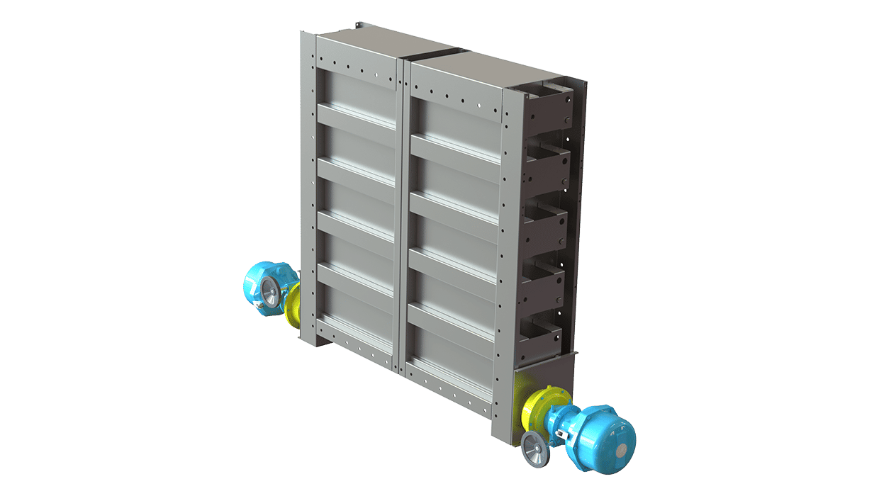
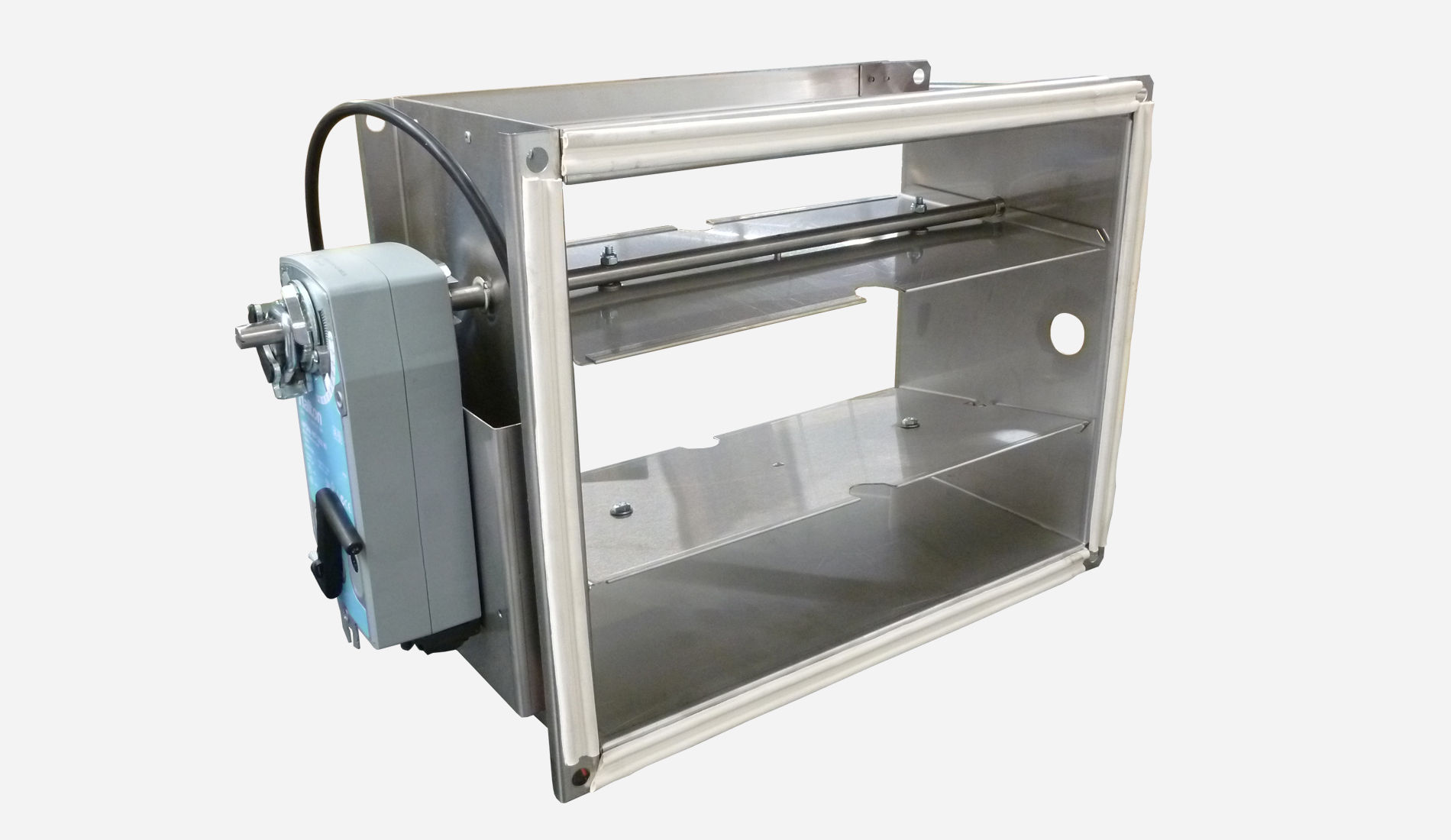
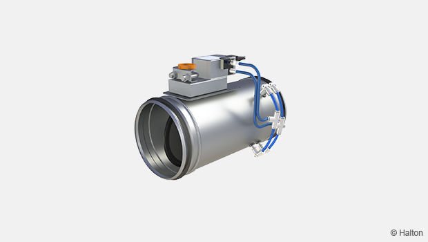
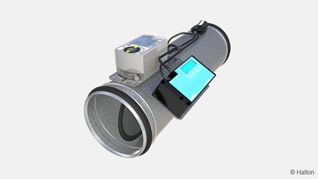
The type CID-01 Isolation Damper has been specifically designed to meet the tightest shut- off requirements of the industrial and nuclear markets, where isolation of ducting for filter replacement or duct inspection is required, without shutting down complete systems.
Overview
- The Safety Function of the Isolation Damper when actuated is to close and control pressure system balancing or recirculation of air. This function may be used in both high or low demand mode applications
- Each damper is tested to ensure there is zero leakage through the blades and casing
- Has been assessed by Sira Certification Service with reference to the CASS methodologies and found to meet the requirements of IEC 61508-2:2010
- Damper has achieved a SIL 2 rating
Specification
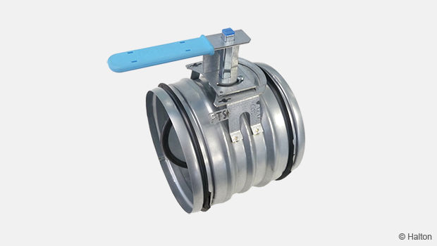
The type CID-01 Isolation Damper has been specifically designed to meet the tight shut- off requirements of the industrial and nuclear markets, where isolation of ducting for filter replacement or duct inspection is required, without shutting down complete systems. These versatile dampers can be automatically or manually operated and can be supplied with pre-drilled flanges to ease installation.
The dampers may be installed vertically or horizontally with the air flow in one direction.
Each complete damper assembly is subjected to a works pressure test of 10,000 Pa for one hour. The upstream end of the damper is sealed during the test and the pressurizing source removed. After one hour the pressure is checked to ensure that it has not dropped taking into consideration any changes in air temperature.
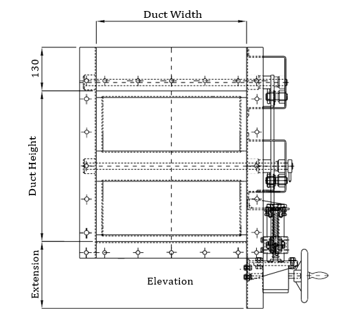
Dimensions
Casing
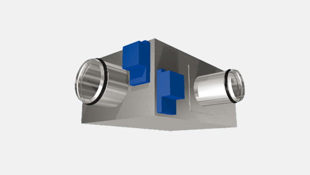
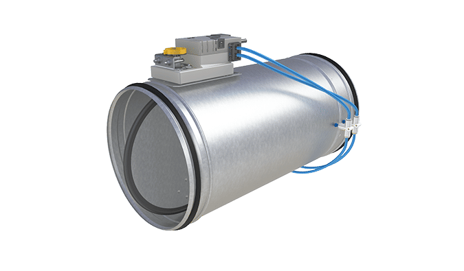
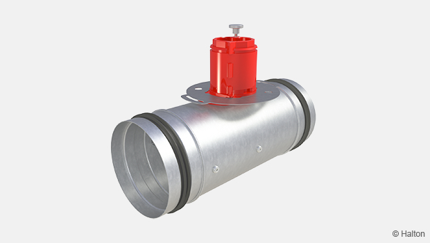
The damper casing is formed from 3.0 mm thick sheet steel into a rigid channel section to ensure proper alignment of blades and shafts. Where circular dampers are required, additional spigot adaptors are used which increase the damper insertion length from 350 to 450 mm.
Blades
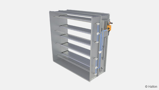
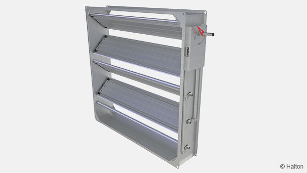
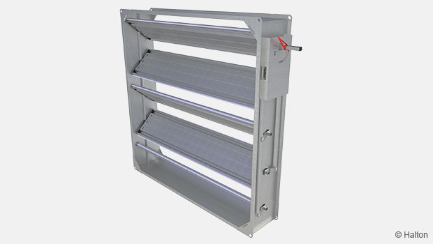
The blades are a formed single skin of 3.0 mm sheet steel fitted with a closed cell pad that seals against a frame within the damper casing to provide 100% isolation.
Shafts
Continuous shafts Ø 19.05 mm with welded pivoted- blade support at each end.
Linkage
Parallel action linkage consisting of drive levers and bosses connected by flat bar link bars, driven through stainless steel pins. All linkage is contained within the depth of the casing.
Bearings
Phosphor bronze self-lubricated plain ‘Oilite’ bushes fitted into bearing bosses welded to the outside of the casing.
Shaft seals
Lipseal type fitted into each bearing boss.
CID-01 General Drawings
Material and Finishing
| Part | Material | Finishing |
| Case | Steel | Painted or Galvanised |
| Case | Stainless Steel – 1.4307 (304L) Stainless Steel – 1.4404 (316L) |
– |
| Blades | Steel | Galvanised |
| Blades | Stainless Steel – 1.4307 (304L) Stainless Steel – 1.4404 (316L) |
– |
| Shafts | Stainless Steel – 1.4307 (304L) Stainless Steel – 1.4404 (316L) |
– |
| Bearings | Phosphor bronze self-lubricated plain ‘Oilite’ | – |
Product Models and Accessories
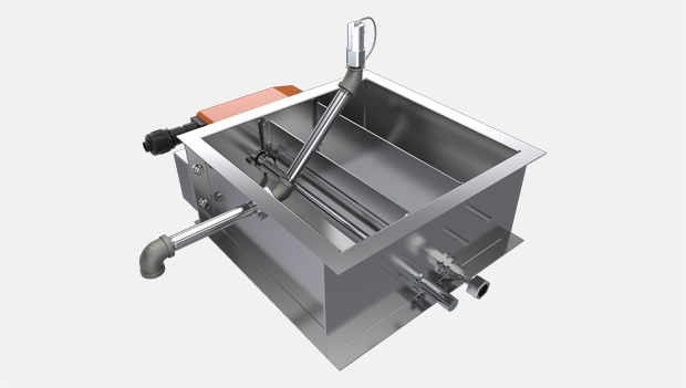
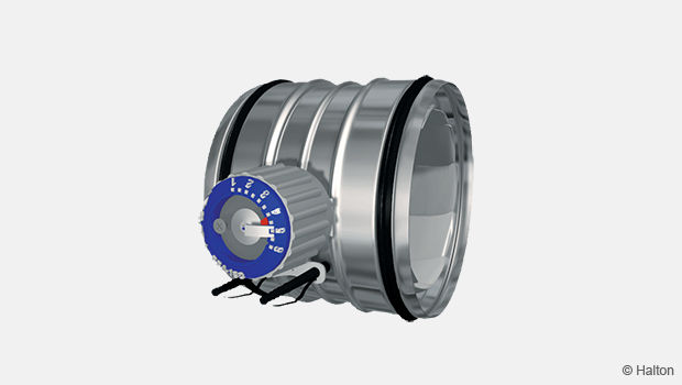
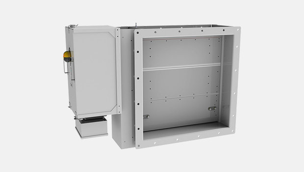
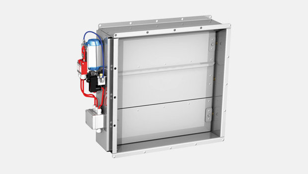
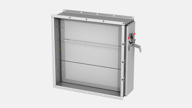
- Damper can be supplied with either; Pneumatic Actuator, Electric Actuator, Manual Handwheel
- Earth continuity bosses can be supplied upon request
- Lifting lugs are provided to allow safe lifting of the damper
- Solenoid Valves
- Remote Indication of damper blade position using microswitches
- Local Indication of damper blade position
Other variations to suit clients’ specific requirements are also available. Please contact sales staff for further details
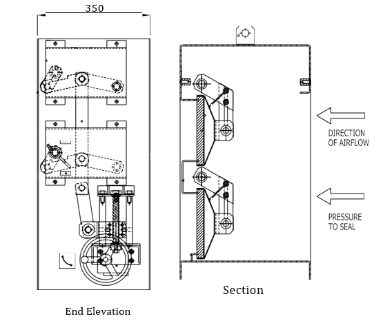
Operation Principle
The Safety Function of the Isolation Damper when actuated is to close and control pressure system balancing or recirculation of air. The damper blades are fitted with a closed cell pad that seals against a frame within the damper casing to provide 100% isolation, allowing for work to be carried out within the duct network or stopping the spread of contaminates. Please note the damper is not bi-directional and air flow must be as shown in the general drawings above.
Weights
Please note the below table gives bare shaft damper weights only at the given square dimensions. Weights for specific sizes are issued on the quotation document.
| Damper size (mm) | Est. weight | ||
| Width/Dia. | Height | Depth | |
| 150 | 150 | 450 | 51 kg |
| 200 | 200 | 350 | 40 kg |
| 250 | 250 | 350 | 43 kg |
| 300 | 300 | 350 | 47 kg |
| 350 | 350 | 350 | 76 kg |
| 400 | 400 | 350 | 80 kg |
| 450 | 450 | 350 | 85 kg |
| 500 | 500 | 350 | 90 kg |
| 550 | 550 | 350 | 95 kg |
| 600 | 600 | 350 | 127 kg |
| 650 | 650 | 350 | 132 kg |
| 700 | 700 | 350 | 138 kg |
| 750 | 750 | 350 | 144 kg |
| 800 | 800 | 350 | 150 kg |
| 850 | 850 | 350 | 185 kg |
| 900 | 900 | 350 | 192 kg |
| 950 | 950 | 350 | 199 kg |
| 1000 | 1000 | 350 | 206 kg |
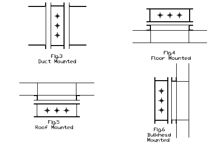
Installation
Dampers can be duct mounted, floor mounted, roof mounted, or bulkhead mounted depending upon the application.
Downloads
Request for Quotation
"*" indicates required fields
ABD – Automaattinen säätöpelti (CE)
product
ABD – Automaattinen tasapainotuspelti
product
CID -01 – Täysin tiivis eristyspelti
product
Halton HFD – Ilmavirran säätöyksikkö
product
Halton Max MLC – Ilmavirtasäädin (VAV)
product
Halton Max MOC – Ilmavirtasäädin
product
Halton Max MUC – Ultraääni ilmavirtasäädin (VAV)
product
Halton PRA – Ilmavirran säätöpelti (CAV)
product
Halton PTS – Ilmavirran säätöpelti (yksiläppäinen)
product
Halton RMC – Vakioilmavirran säätöpelti (CAV)
product
Halton UKV – Ilmavirtasäädin
product
Halton UTK – Monisäleinen ilmavirran säätöpelti (CAV)
product
Halton UTT – Monisäleinen ilmavirran säätöpelti (CAV)
product
UTA – Kaasutiivis sulkupelti
product
UTG – Gastight shut-off damper
product
UTP – Tasapainotuspelti
product