Product / VEX
Halton Vita Extract (VEX) – Gas and smoke extraction solution
Halton Vita Extract is a gas and smoke extraction solution for medical use.
It enables the extraction of anaesthetic gases and surgical smoke.
- Removes hazardous gases and minimises exposure to unhealthy substances
- Energy-efficient performance ensured by one or several frequency controllers
Overview
Halton Vita Extract is a gas and smoke extraction solution for medical use. It enables the extraction of anaesthetic gases and surgical smoke.
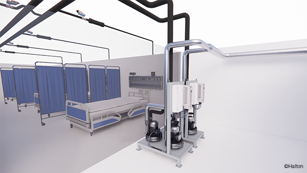
Halton Vita Extract provides a healthier working environment by removing hazardous gases directly from the source. Anaesthetic gases exhaled by the patient can be collected and extracted with the help of a double mask. Surgical smoke can be collected straight from the diathermy device or from the vicinity of the surgical area where the smoke is generated.
The vacuum is generated by one or multiple blower fans of the central unit that is typically located in a ventilation machine room. Vacuum piping is routed throughout the building to individually controlled suction inlets.
Application areas
- Smoke extraction in diathermy and laser cutting surgery (operating rooms)
- Gas extraction in anaesthesia (operating rooms, recovery rooms)
- Gas extraction in pain relief (delivery rooms)
Key features
- Removes hazardous gases and minimises exposure to unhealthy substances
- Energy-efficient performance ensured by one or several frequency controllers
- Reliable performance and high-quality components
- Low maintenance need
- Connectivity with Building Management System (BMS)
Offering
The Halton delivery includes all functional system components (central units, suction inlets, control panels, and control valves) as well as design support and the start-up (commissioning) of the system.
Note: The pipework is not included in the delivery.
Operating principle
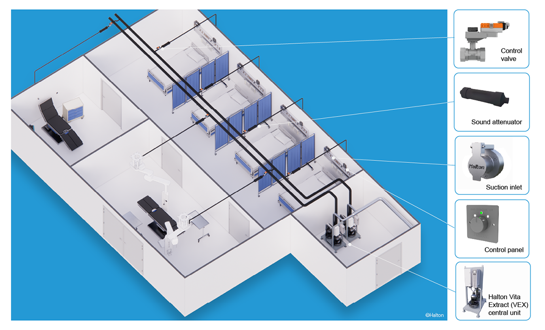
Fig.1. Halton Vita Extract system
The system can have multiple suction inlets that are connected to the trunk pipework. The medical equipment (patient masks or diathermy devices) can be connected to the suction inlets. The vacuum blowers in the central unit generate a constant vacuum pressure in the pipework. The vacuum extracts the gases out of the medical equipment and forces them out through the exhaust piping. The vacuum airflow for each suction inlet can be adjusted with the control valves that can be operated manually or with an actuator. Dedicated sound attenuators suppress pipe noises for the user’s comfort.
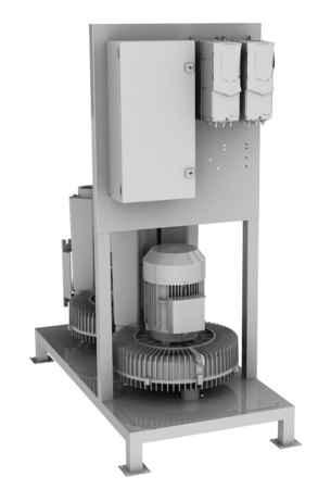
In central unit model ‘secure’, the unit’s blowers and other critical components are duplicated to ensure the system continues running during maintenance or in case there is a component failure. A built-in surveillance function automatically starts using a secondary component if a primary component in the system fails. For maintenance, the blowers and motor drives can be separately disconnected from the power supply. The connecting piping between the two blowers includes one-way valves to prevent vacuum leak through the other blower during maintenance.
Services
Halton design support
- Co-designing with the customer: defining the requirements and performance targets, matching the targets to an optimal solution.
Halton Tune
- Halton Vita solutions always include on-site commissioning to ensure the safety and functionality of the solutions.
- Verifying and adjusting the optimal performance of systems.
- Service personnel and end user training.
Halton Life Cycle
- Halton offers a maintenance agreement for installed systems. As part of this service, the Halton service team tests all the critical components and the system operation to ensure continuous functionality of the solution.
Features and options
Feature |
Description |
| Motor drive | Energy-efficient variable speed drive with a frequency controller |
| Vacuum measurement | Differential pressure transmitter |
| Vacuum level | Vacuum pressure, can be set between 50-150 mbar |
| Redundancy | All critical components duplicated (secure model), a weekly alternation between the motors |
| Maintenance | Minimal maintenance needs, even on continuous operation |
| Airflow control | Options:
|
| Suction inlet | Options:
|
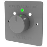
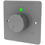
| Control panel | Options:
|
| Actuator position indication | Indicator LEDs on the control panel:
|
Table 1. Halton Vita Extract features and options
System components
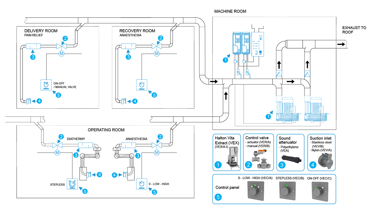
Fig.2. Overview of Halton Vita Extract system components
Key
- Central unit
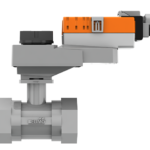
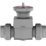
- Control valve
- Sound attenuator
- Suction inlet
- Control panel
Component |
Description |
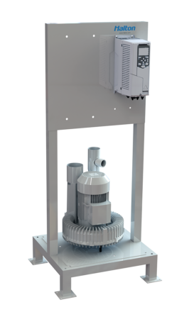
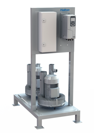
| Central unit
Single:
Dual:
Secure:
|
Contains the following:
For more information on the models, see Key technical data. |
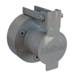
| Suction inlet
|
Options:
|
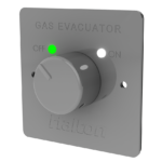
| Control panel
|
|
| Control valve
|
Can be operated manually or with an actuator:
|
| Sound attenuator
|
|
Specification
The system must fulfil the following requirements:
System performance
- Enables the extraction of anaesthetic gases and surgical smoke directly from the source.
- Improves the safety of the operating personnel by reducing exposure to surgical smoke and anaesthetic
gases.
System components
- The system consists of a central unit as well as control valves, actuators, sound attenuators, suction inlets, and control panels.
- The vacuum blowers in the central unit generate a constant vacuum pressure in the pipework.
- Three central unit models: single, dual, and secure
- Each model available in three sizes (S, M, L)
- The system can have multiple suction inlets that are connected to the trunk pipework.
- The medical equipment (patient masks or diathermy devices) can be connected to the suction inlets.
- The vacuum extracts the gases out of the medical equipment and forces them out through the exhaust piping.
- The vacuum airflow for each suction inlet can be adjusted with the control valves that can be operated manually or with an actuator.
- The vacuum airflow for each suction inlet can be controlled with a control panel. The control panel options are the following: on-off, 0-low-high, 0-100%.
- A dedicated sound attenuator to suppress flow noise.
Design considerations
When designing a Halton Vita Extract system, consider the following:
- The location of the central unit (usually installed in a ventilation machine room).
- The size (capacity) of the central unit (selected according to the desired airflow and vacuum pressure).
- The piping and suction inlet materials.
- The pipework design from the suction inlets to the central unit (pipe sizes).
- Pipe diameters should decrease gradually from the central unit to the furthest suction inlet connection.
Note: The pipework should be designed so that unnecessary pressure losses are avoided. This is why it is recommended that two 45° elbows are used instead of one 90° elbow and that 45° T-branches are used instead of 90° T-branches.
- Pipe diameters should decrease gradually from the central unit to the furthest suction inlet connection.
- The airflow control method
- Manual
To stop suction, the hose must be removed from the suction inlet. The manual method can be used when there is no need to adjust the air volume or stop the vacuum when medical equipment is connected. - Actuator adjustment
The suction can be stopped from the control panel (without detaching medical equipment).
- Manual
- What information needs to be sent from the central unit to the Building Management System (BMS)?
Pipework design
- Pipe diameters should decrease gradually from the central unit to the furthest suction inlet connection.
- The air velocity should always be below 10 m/s.
Pipe diameter (mm) |
Number of users (-) |
Air volume (l/min) |
Max.length (m) |
| 40 | 1 | 620 | 15-20 |
| 50 | 1-2 | 1000 | 15-20 |
| 63 | 2-3 | 1670 | 15-20 |
| 75 | 4-6 | 2350 | 15-20 |
| 90 | 5-8 | 3350 | 30-40 |
| 110 | 8-12 | 5000 | 30-40 |
| 125 | 11-16 | 6500 | 50 |
| 160 | 18-25 | 10800 | 50 |
| 300 | 26-39 | 16500 | 50 |
Table 4. Pipe diameter sizing
Design examples
Halton Vita Extract for a hospital with 16 operating rooms
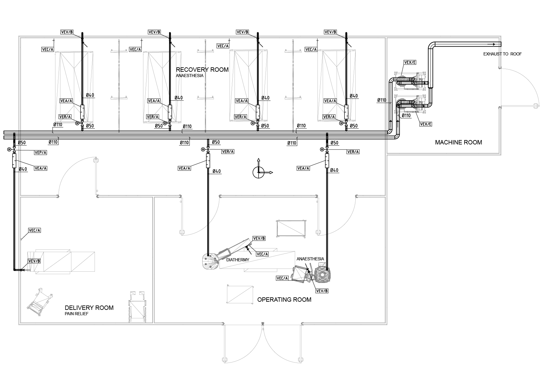
Fig.3. Plan drawing example of a Halton Vita Extract system
Description
In this configuration, Halton Vita Extract takes care of extracting the anaesthetic gases and surgical smoke from 16 operating rooms. Each operating room has suction inlets for both surgical smoke and anaesthetic gases. The system operation is secured (100% redundancy).
Design criteria
- 16 operating rooms
- Suction inlets for surgical smoke
- Airflow per suction inlet 30 m3/h. Total for 16 rooms: 480 m3/h
- Required vacuum pressure 10 kPa (100 mbar)
- Suction inlets for anaesthetic gases
- Airflow per suction inlet 35 m3/h. Total for 16 rooms: 560 m3/h.
- Required vacuum pressure 5 kPa (50 mbar)
- 100% redundancy
Components
Based on the design criteria, the system components are selected as follows:
- Central unit for surgical smoke extraction: VEX L secure (airflow up to 617 m3/h / 10 kPa)
- Central unit for anaesthetic gas extraction: VEX L secure (airflow up to 677 m3/h / 5 kPa)
- Motorised valves used for all suction inlets
- Suction inlets for surgical smoke extraction controlled with stepless 0-100% control panels.
- Suction inlets for anaesthetic gas extraction controlled with 3-step 0-low-high control panels.
Example order codes
- 2 x central unit (VEX L secure), one for surgical smoke extraction and one for anaesthetic gas extraction (VEX/I)
- 32 x suction inlet, stainless steel (VEV/B)
- 16 x control panel, stepless 0-100% (VEC/B)
- 16 x control panel . 3-step 0-low-high (VEC/A)
- 32 x valve package (VER/A)
- 32 x sound attenuator (VEA)
Key technical data
Technical data common to all Halton Vita Extract central unit models
- System vacuum pressure level pre-set between 50-150 mbar.
- Requires a 400 V (three-phase) 16 A wall socket, without fault current protection. Other voltages are available upon request.
- Can be connected to and controlled from a Building Management System (BMS). Potential free status information is available as standard. Field bus connection is optional.
Technical data of Halton Vita Extract central unit, single model
Feature |
VEX S single |
VEX M single |
VEX L single |
| Redundancy percentage of airflow values / Number of blower motors | Redundancy 0% 1 motor |
Redundancy 0% 1 motor |
Redundancy 0% 1 motor |
| Nominal motor power | 2.2 kW (4.4 A) | 4.0 kW (7.6 A) | 5.5 kW (10.1 A) |
| Maximum air volume -50/-100/-150 mbar pressure |
280/250/215 m3/h | 440/400/360 m3/h | 677/617/557 m3/h |
| Unit weight | 126 kg | 162 kg | 180 kg |
Technical data of Halton Vita Extract central unit, dual model
Feature |
VEX S dual |
VEX M dual |
VEX L dual |
| Redundancy percentage of airflow values / Number of blower motors | Redundancy 50% 2 motors simultaneously when full airflow |
Redundancy 50% 2 motors simultaneously when full airflow |
Redundancy 50% 2 motors simultaneously when full airflow |
| Nominal motor power | 4.4 kW (8.8 A) | 8.0 kW (15.2 A) | 11.0 kW (20.2 A) |
| Maximum air volume -50/-100/-150 mbar pressure |
560/500/430 m3/h | 880/800/720 m3/h | 1354/1234/1114 m3/h |
| Unit weight | 185 kg | 257 kg | 323 kg |
Technical data of Halton Vita Extract central unit, secure model
Feature |
VEX S secure |
VEX M secure |
VEX L secure |
| Redundancy percentage of airflow values / Number of blower motors | Redundancy 100% 2 motors alternately |
Redundancy 100% 2 motors alternately |
Redundancy 100% 2 motors alternately |
| Nominal motor power | 2×2.2 kW (4.4 A) | 2×4.0 kW (7.6 A) | 2×5.5 kW (10.1 A) |
| Maximum air volume -50/-100/-150 mbar pressure |
280/250/215 m3/h | 440/400/360 m3/h | 677/617/557 m3/h |
| Unit weight | 185 kg | 257 kg | 323 kg |
Note: For surgical equipment, the vacuum capacity must be re-calculated in each case, so the number of maximum users may vary depending on specific needs.
Dimensions and weight
Central unit
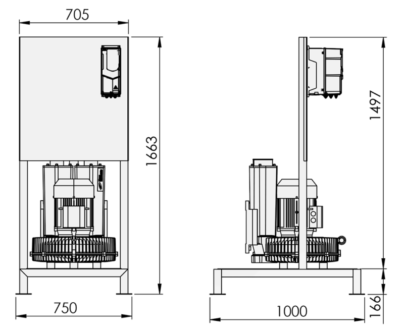
Fig.4. Dimensions of Halton Vita Extract central unit (single)
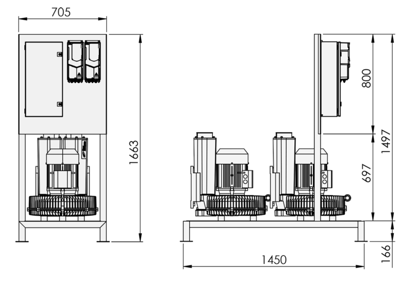
Fig.5. Dimensions of Halton Vita Extract central unit (dual and secure)
For information on the weight of the central unit, see Key technical data.
Control panel
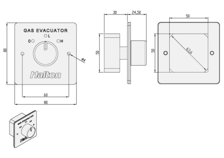
Fig.6. Control panel dimensions
Note: The mounting box type should be designed according to these dimensions.
Control valve
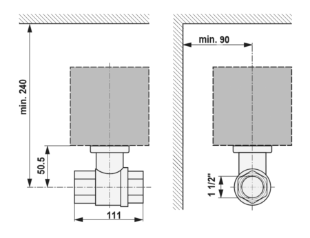
Fig.7. Control valve dimensions
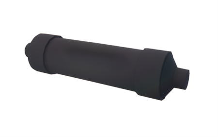
Sound attenuator
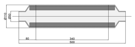
Fig.8. Sound attenuator dimensions
Order code
VEX/M
M = Model
A S / single (2.2 kW)
B M / single (4.0 kW)
C L / single (5.5 kW)
D S / dual (2.2 kW+2.2 kW)
E M / dual (4.0 kW+4.0 kW)
F L / dual (5.5 kW+5.5 kW)
G S / secure (2.2 kW+2.2 kW)
H M / secure (4.0 kW+4.0 kW)
I L / secure (5.5 kW+5.5 kW)
Sub products
VEA Sound attenuator (L500)
VER/A Flow control valve and actuator (230V)
VER/B Manual flow control valve
VEC/A Control panel (0-Low-High)
VEC/B Control panel (0…100 %)
VEC/C Control panel (on-off)
VEV/A Suction inlet, nylon
VEV/B Suction inlet, stainless steel (AISI 304)
Code example
VEX/A