Product / MSS
Overview
- Pressure transmitter equipped with automatic zero point calibration to ensure continuous accuracy
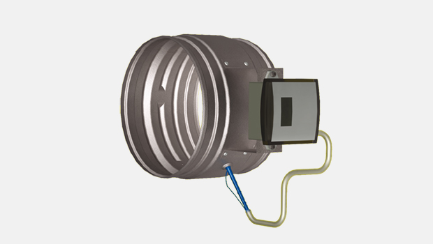
- Circular duct static pressure measurement unit comprising measurement element and pressure transmitter with LCD display
- Adjustable pressure measurement range 0…1000 Pa
- Accurate measurement, inaccuracy less than ± 10 % in typical applications
- Pressure transmitter equipped with automatic zero point calibration to ensure continuous accuracy
- Available in sizes Ø200 … Ø 500
- Classification of casing leakage EN 1751 class C
- Duct spigots have integrated rubber gaskets
Accessories
- Integrated electronic static pressure transmitter unit
Dimensions and weight
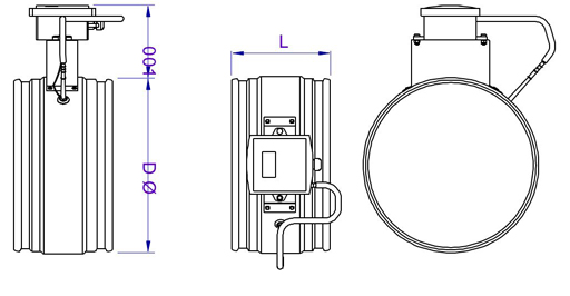
| NS | L | ØD |
| 200 | 142 | 199 |
| 250 | 142 | 249 |
| 315 | 142 | 314 |
| 400 | 195 | 399 |
| 500 | 195 | 499 |
Weight
| NS | kg |
| 200 | 0,9 |
| 250 | 1,1 |
| 315 | 1,3 |
| 400 | 2,3 |
| 500 | 2,9 |
Material
| Part | Material | Note |
| Casing | Galvanised steel | – |
| Measurement tube | Silicone | – |
| Measurement tab | Polyurethane | – |
| Duct gaskets | 1C-polyurethane hybrid | – |
| Transmitter Enclosure | Polycarbonate | IP54 |
Duct connection gaskets are vulcanised to the casing.
Function
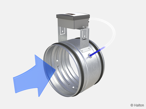 Fig.1. Halton MSS with HDE-PE
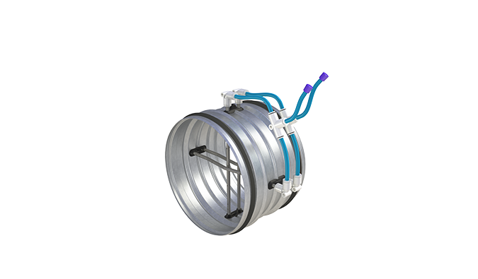
Duct static pressure is accurately determined using multipoint averaging measurement. The duct static pressure is measured between the Halton MSS measurement tab and the reference space. The pressure of reference space represents the air pressure of the spaces in the ventilation system’s service area (see Installation section).
The Halton MSS unit includes static type pressure measurement sensor with a digital display of the actual pressure value. The measured value is transmitted using 0 to 10 volt signal.
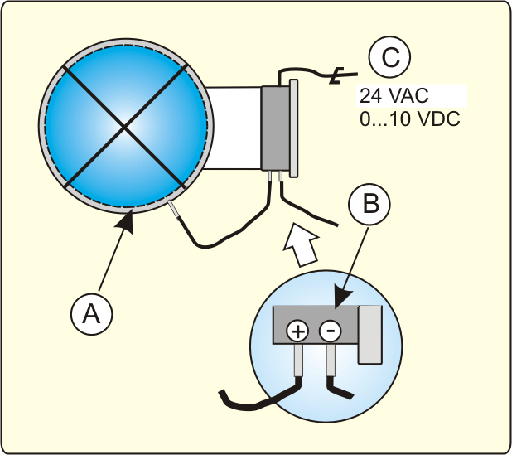
Key:
A Pressure measurement chamber
B Pressure measurement tube connection points
C Power supply and output signal.
Continuous accuracy is assured by automatic zero point calibration of pressure sensor. Thus, no manual re-calibration is needed in normal operating conditions.
Installation
The static pressure measurement unit must be installed in a space where ambient temperature is between 0 and 45°C.
Ductwork installation, safety distances
In order to ensure the accuracy of the duct static pressure, measurement the safety distances between the measurement unit and flow disturbances (e.g. bends, T-branches) must be respected. The necessary safety distances before and after different disturbances are presented in figures below.
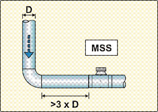
Fig.1. 90° elbow
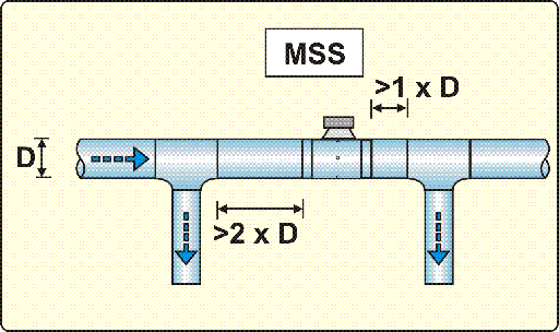
Fig.2. Branch on supply duct
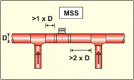
Fig.3. Branch on exhaust duct
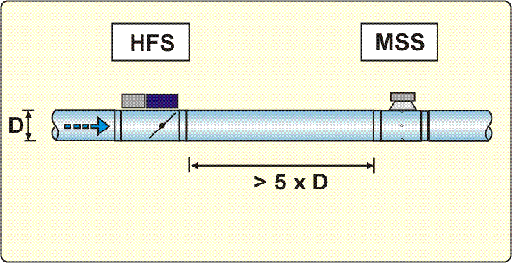
Fig.4. Safety distance between MDC/HFS control damper and MSS, straight duct
Measurement tube connections
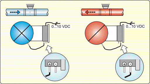
Connect the pressure measurement tube from the unit to the sensor, either to +/- taps, according to the exhaust/supply application. Supply connection is the default factory setting.
In typical installations the reference pressure inlet (+ for exhaust installation and – for supply installation) is left open at the ambient air. If necessary, the reference pressure can be connected to the reference pressure inlet by the contractor using Ø 6/4 mm measurement tubes.
Connection of measurement tube to the transmitter in supply and exhaust installations.
Electric connections
1. Power supply, 24 VAC / 24 VDC
2. Neutral, 0 V
3. Output signal, 0 to 10 VDC, < 2 mA
Power supply is wired from pressure control damper.
Technical data of the pressure transmitter
Supply voltage: 22…28 VAC/VDC
Power consumption: < 1.5 VA 24 VAC, < 1.0 VA 24 VDC
Measurement ranges:
- 0…100 Pa
- 0…200 Pa (factory default)
- 0…500 Pa
- 0…1000 Pa
- 0…2500 Pa (not to be used with Halton MDC or Halton HFS)
Operating temperature 0 …+45ºC
Maximum overpressure 25 kPa
Enclosure IP 54, polycarbonate
Dimensions (width x height x depth) 115 x 115 x 45 mm
Measurement
The Halton MSS unit includes static type pressure measurement sensor with digital display.
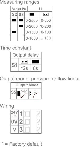
Adjustable pressure measurement ranges corresponding to 0-10 VDC output signal are:
- 0…100 Pa
- 0…200 Pa (Factory default)
- 0…500 Pa
- 0…1000 Pa
- 0…2500 Pa (Not used)
Pressure measurement range is set with jumpers according to the diagram below:
Delay selection
Pressure measurement output signal delay of 2 s is designed to be used in Halton MDC/HFS control damper and Halton MSS applications.
Measurement tubes
+ Higher pressure
– Lower pressure
Inaccuracy of the Halton MSS is a function of measured static pressure and air velocity in ventilation duct. In undisturbed flow conditions inaccuracy is less than ± 10% when:
- Static pressure > 40 Pa and air velocity < 6 m/s
- Static pressure > 100 Pa and air velocity < 10 m/s
Continuous accuracy is assured by automatic zero point calibration of pressure sensor. Thus, no manual re-calibration is needed in normal operating conditions.
Specification
The casing of the measurement unit is made of galvanised steel.
The flow measurement probe pipes is made of aluminium.
The measurement unit has integral gaskets.
The unit has integrated pressure transmitter (0-10V signal) with display showing measured value.
Order code
MSS-D; PT-ZT
D = Size of duct connection (mm)
200, 250, 315, 400, 500
Other options and accessories
PT = Difference pressure transmitter
P1 HDP-PE
P2 VRU-D3-BAC
ZT = Tailored product
N No
Y Yes (ETO)
Code example
MSS-200, PT=P1, ZT=N
