Product / KWT
Overview
- The design follows USPHS guidelines
- Automatic periodic cleaning of the exhaust plenum and KSA grease filters (and UV tubes when applicable)
- Minimal maintenance requirements, reducing the work load for personnel cleaning the filters and ductwork
- High level of hygiene facilitated
- Prevention of the build-up of grease deposits, which pose a serious fire hazard
- Halton Capture Jet™ technology, reducing the required exhaust airflow rate and improving the capture and containment efficiencies of the hood, while reducing energy use
- Draught-free air supply directly to the work area from the low-velocity supply unit located on the front panel of the hood
- High-efficiency grease filtration using Halton KSA multi-cyclone filters
- Supplied as standard with lighting, balancing dampers for supply, capture and exhaust air and T.A.B.™ airflow measurement taps, which allow accurate and effective balancing of airflows, and efficient commissioning
Specification
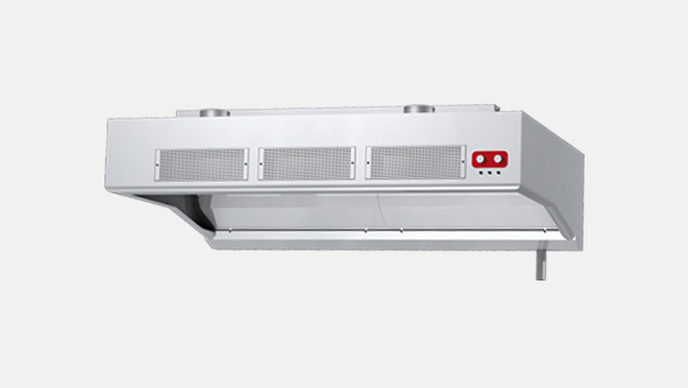
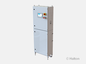
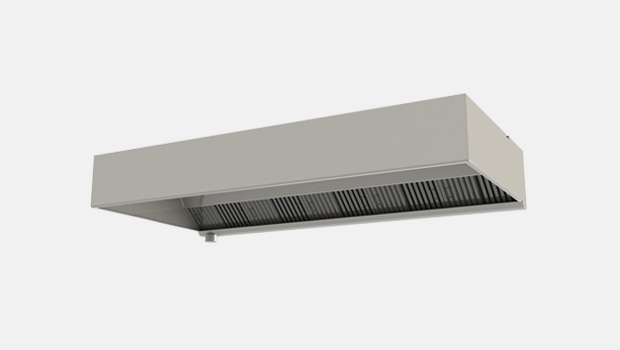
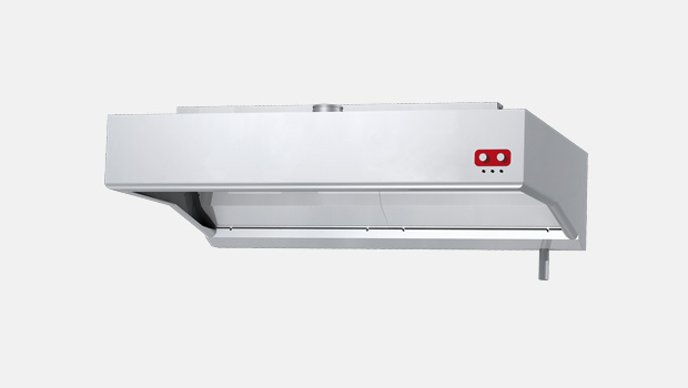
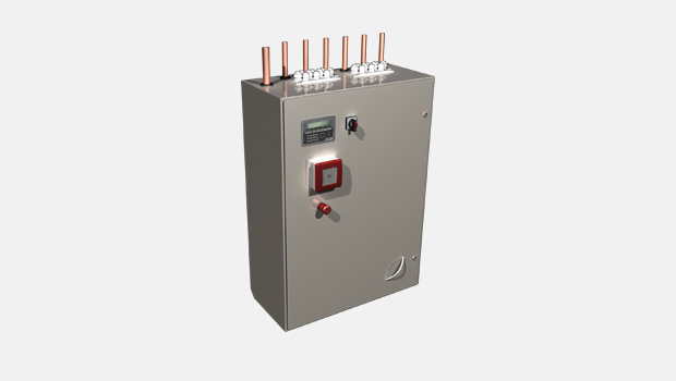
Halton KWT is a galley water wash hood for use in marine & offshore applications. The highly efficient KWT hood uses Halton Capture Jet™ technology, which allows the hood to operate with up to 30% lower exhaust airflow rates than traditional hoods. The KWT galley hood automatically washes down the grease filters without the need for removal of the filters from the hood. The washing cycle, operated by a control cabinet CCW-M or WR (see separate brochure), is fully automatic and programmable for use in different operating conditions. The washing process can be manually overridden, when required.
Dimensions
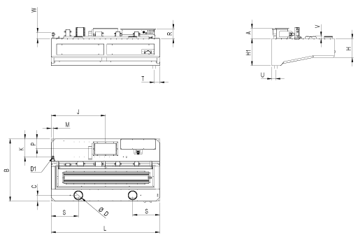
KWT general drawings
| A | 195 | L | 1000-3000 |
| B | 1100-1900 | M | 37 |
| C | 110 | P | 185 |
| D | 100-200 | S | 1/2L |
| D1 | 3/4” | T | 100-200 |
| H | 350 | U | 70 |
| H1 | 500 | R | 185 |
| J | 1/2L | V | max 50 |
| K | 332 | W | ~130 |
Note: Maintenance / light fixture hatch is as big as the construction allows.
Note: Note: Minimum length with UV-light technology is 1250 mm.
Material
| PART | MATERIAL | THICKNESS | NOTE |
| Front and side walls | Stainless steel EN 1.4301 (AISI304) | 2 mm | Option: EN 1.4404 (AISI316L) |
| Main body | Stainless steel EN 1.4301 (AISI304) | 1,25 mm | Option: EN 1.4404 (AISI316L) |
| Light fixture | Painted steel | – | – |
| Wash piping | Stainless steel, brass | – | – |
| Cables | Halogen free | – | – |
Construction
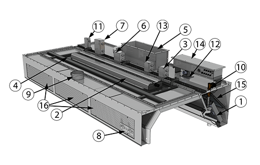
PARTS
1 KSA grease filters
2 Lighting fixture
3 Lighting fixture power supply junction box
4 Maintenance hatch
5 Exhaust air connection, fire damper or shut-off damper* (available as an option) and adjustment damper
6 Fire damper junction box
7 Actuator power and fuse info junction box
8 Damper switch and indication (available as an option)
9 Supply air connection and adjustment damper
10 Water wash piping connection R3/4” (G3/4” solenoid valve as an option)
11 Washing solenoid valve junction box
12 UV system, available as an option
13 UV power supply junction box, available as an option
14 UV control junction box, available as an option
15 Mesh filter, available as an option, 16 Supply air panels
*If fire or shut-off damper is located at the duct, Halton suggests two default solutions for duct connection:
- Eurovent-collar with flange
- Welded L-collar
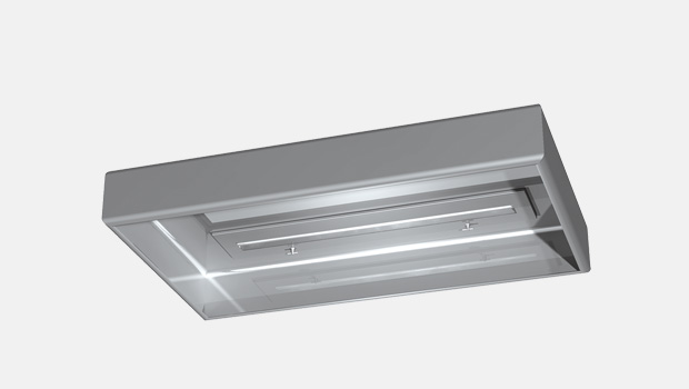
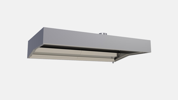
The KWT hood comprises a Capture Jet™ air supply module, a light fixture, adjustment dampers, airflow measurement taps and KSA grease filters. All parts of the hood are manufactured from polished stainless steel EN 1.4301 (AISI304). The joints at the lower edges of the device are watertight. A drain pipe connection is fitted into the exhaust plenum in order to enable removal of the grease and dirt extracted by the KSA multi-cyclone filters and to drain the washing water. The Capture Jet™ / supply plenum is thermally insulated through the use of mineral wool material to prevent condensation on the inner face above the cooking equipment.
Eurovent-collar with flange
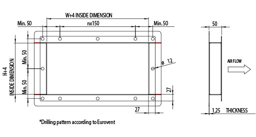
Welded L-collar

Weights of standard KWT hoods (kg)
| B/L | 1200 | 1600 | 2000 | 2500 | 3000 |
| 1100 | 105 | 127 | 148 | 176 | 203 |
| 1300 | 110 | 133 | 155 | 184 | 212 |
| 1500 | 116 | 140 | 162 | 193 | 221 |
| 1700 | 122 | 146 | 169 | 201 | 230 |
| 1900 | 127 | 153 | 177 | 209 | 240 |
The above table represents an indication of different size of average KWT hoods. Weight does not include a fire damper.
Weights of standard KWT hoods with UV-lights (kg)
| B/L | 1250 | 1600 | 2000 | 2500 | 3000 |
| 1100 | 149 | 172 | 198 | 232 | 264 |
| 1300 | 155 | 179 | 205 | 240 | 274 |
| 1500 | 161 | 185 | 212 | 249 | 283 |
| 1700 | 166 | 192 | 220 | 257 | 292 |
| 1900 | 172 | 198 | 227 | 265 | 301 |
The above table represents an indication of different size of average KWT hoods with UV-light technology. Weight does not include a fire damper.
Options and Accessories
- Non-standard spigots: choice of size and position
- UV-light filtration – a combination of KSA filter, mesh filter and ultraviolet-light technology
- Certified fire damper manufactured of EN 1.4301 (AISI 304) or EN 1.4404 (AISI 316L)
- Wet chemical fire suppression system
- M.A.R.V.E.L. demand-based ventilation system
- Possibility to have a separated make up air and capture air
- M.A.R.V.E.L. demand based ventilation system
- More accessories under Product Code
Function
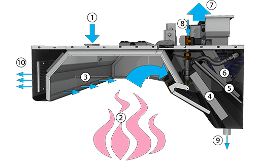
- Supply air enters the Capture Jet plenum.
- Contaminated air and heat rises from the cooking appliances.
- Contaminated air is directed into the hood by Halton patented Capture Jet technology.
- KSA multi-cyclone filters remove grease and contaminants from the air stream with the aid of centrifugal effect. According to independent laboratory tests KSA is the most efficient mechanical grease filter on the market.
- Mesh filter balances the airflow inside exhaust plenum and apply more filtration to the air. Together with KSA filter this doubles filtration efficiency. Mesh filter is available as an option.
- Based on Halton’s patented highly efficiency Capture JetTM solution and advanced mechanical KSA filter technology, the UV-light technology with scheduled maintenance keeps the plenum and duct virtually grease-free and mitigates the cooking odor and emissions.
The grease vapor and effluents that are not collected by high-efficiency filters pass over the lamps. This causes a chemical reaction that destroys the grease and converts it into carbon dioxide and water vapor. The chemical action carries over into the duct and helps keep the duct and exhaust fan clean. UV-filtration is available as an option. - Cleaned exhaust air contains small amounts of Ozone which further cleans the ducts downstream. All excess Ozone converts back into Oxygen.
- At scheduled times the washing control cabinet stops the hood operation and begins a washing cycle. Hot water with mild detergent is pumped into the hood spray nozzles, washing the essential parts of the exhaust plenum including UV-lights and filters.
- The waste from the washing cycle is drained from the hood via the drain connection.
- Supply air is distributed to the workspace at low velocity through the front panels.
Recommended exhaust airflow for KWT
| NUMBER OF KSA FILTERS | ||||
| MINIMUM l/s | MAXIMUM l/s | MINIMUM m3/h | MAXIMUM m3/h | |
| 1 | 130 | 201 | 468 | 724 |
| 2 | 259 | 402 | 932 | 1447 |
| 3 | 389 | 602 | 1400 | 2167 |
| 4 | 518 | 803 | 1865 | 2891 |
| 5 | 648 | 1004 | 2333 | 3614 |
| 6 | 778 | 1205 | 2801 | 4338 |
Note: KSA filter size 500x330x50 mm
Specification
Suggested specification
General
The water wash galley hoods shall be constructed from stainless steel EN 1.4301 (AISI304). The galley hoods shall be supplied complete with outer casing / main body, supply air plenum, supply air panels, pressure measurement taps, supply and exhaust air spigot connections with adjustment damper, maintenance hatch, light fixture, capture air jet, grease filters, drain connection, automatic washing system controlled by separate control cabinet with interfaces to ships safety systems. Classified fire damper in each exhaust connection. The manufacture of all galley hoods shall be controlled by ISO 3834-2:2005, ISO 9001, 14001 and OHSAS 18001 standards. The design of hoods shall follow USPHS guidelines.
Construction
All parts shall be constructed of stainless steel sheet EN 1.4301 (AISI304) (thickness 1.25-2.0 mm) with a polished finish. The inside corners of the hood are rounded for easy cleanability according to USPHS guidelines. The joints at the lower edges of the device are welded watertight. All visible screws are thumb screw type. The hood is equipped with a drain connection for removing the dirty water. There is a maintenance hatch in each hood for easy access above hood.
Washing module
Grease filters shall have an automatic washing cycle utilising warm water and detergent via nozzles. The mixing of the detergent occurs within a separate control cabinet. The wastewater shall be removed from the hood by a direct drain connection. The casing of the control cabinet shall be constructed of stainless steel sheet EN 1.4301 (AISI304).
Supply air plenum
The supply air plenum shall be insulated with sealed mineral wool. Plenum can be accessed through a maintenance hatch(es). Part of the galley supply air will be distributed through the low velocity supply air panels located at the front of the hood. Rest of the supply air is used in Capture JetTM technology.
Capture JetTM System
The hood shall be designed with Capture JetTM technology to reduce the exhaust airflow rate required and increase the capture and containment efficiencies of the hood, while reducing energy use.
Airflow measurement taps
Measurement taps shall be located on top of the hood for supply air, capture air and exhaust air measurement.
Demand based filtration
Halton KSA filter
- Minimisation of grease deposits in the ducts
- Enhanced hygiene and safety
The KSA grease filters shall be constructed of stainless steel EN 1.4301 (AISI304). The grease filters shall be supplied in modular size of 500x330x50 mm and shall be removable via two folding handles. The grease filters shall have a honeycomb design in order to allow high grease filtration efficiency with the aid of centrifugal effect in filter honeycombs.
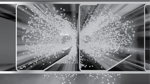
Mechanical filtration is recommended to be used in hoods with low utilization rate and cooking process producing mainly large grease particles (> 8 microns), e.g. food prepared with gas fryers, griddles and broilers (source ASHRAE).
UV-light filtration
Halton’s UV-light technology is the most efficient solution for hoods with medium to high utilization rate and cooking processes producing all sizes of grease particles, e.g. food prepared with electric ranges, griddles and all type of broilers. In the UV-light concept, most of the grease particles are first filtered with mechanical filtration (type KSA). The mesh filter behind the KSA spreads the airflow and the remaining grease particles inside the hood chamber. This increases filtration efficiency up to 50% with grease particles sizes between 5-8 microns. Based on Halton’s patented highly efficiency Capture JetTM solution and advanced mechanical KSA filter technology, the UV-light technology with scheduled maintenance keeps the plenum and duct virtually grease-free and mitigates the cooking odor and emissions.
The grease vapor and effluents that are not collected by high-efficiency filters pass over the lamps. This causes a chemical reaction that destroys the grease and converts it into carbon dioxide and water vapor. The chemical action carries over into the duct and helps keep the duct and exhaust fan clean.
Duct connections
The duct connections and adjustment dampers for supply and exhaust air shall be constructed from stainless steel. The dampers shall be adjustable.
Light fixtures
Each hood shall be delivered with a fluorescent light fixtures or LED light fixtures providing approx. an average illuminance of 500 lux at the work surfaces of the cooking appliances. The light fixtures shall be suitable for a single-phase 230-VAC power supply and shall be manufactured to be of protection class IP67. The ballast and capacitor shall be located within the light frame. The core electric cables connecting the light fixture to the junction box shall be provided.The light fixture shall be installed on a hinged maintenance hatch, allowing access to the hood roof.
Fluorescent light fixture sizes
| HOOD DIMENSION | LENGTH | WIDTH |
| L < 1250 mm, 2×24 W | 720 mm | 220 mm |
| L > 1250 mm, < 2000 mm, 2×39 W | 1020 mm | 220 mm |
| L > 2000 mm, 2×49 W | 1620 mm | 220 mm |
LED light fixture sizes
| HOOD DIMENSION | LENGTH | WIDTH |
| L < 1250 mm, 1×28 W | 720 mm | 175 mm |
| L > 1250 mm, < 2000 mm, 1×42 W | 1020 mm | 175 mm |
| L > 2000 mm, 1×69 W | 1620 mm | 175 mm |
Maintenance hatch
Each hood shall be provided with a maintenance hatch made of stainless steel EN 1.4301 (AISI304) with a shock-resistant plastic window. The heat tolerance of the window shall be up to +115 °C. The hatch shall be easily opened and closed. The maintenance / light fixture hatch is as big as the construction allows.
Airflow measurement
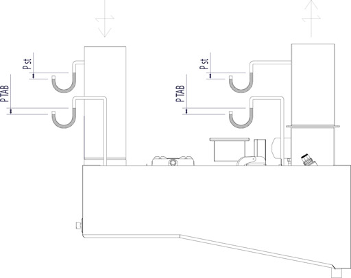
∆Pst = Static pressure loss
∆PTAB = TAB pressure for airflow rate measurement
Product Code
(S)=Model
(N) Shared supply with Capture Jet
(S) Separate supply and Capture Jets
(L)=Length
1000-3000 mm (with UV 1200-3000 mm)
For UV-lights more space is needed
(W)=Width
1100-1900 mm
(H)=Height of front end
350-400 (without waterwash 350-450)
The height of back end is 500 mm
(WF)=Washing Function
(A) Type GE CCW
(B) Type FI WR
(N) No
(UV)=UV-light filtration
(Y) Yes
(N) No
(FD)=Fire damper control
(Y) Yes
(N) No
(MV)=Marvel
(N) No
(A) 1 sensor
(B) 2 sensors
(C) 3 sensors
(D) 4 sensors
(UB)=UV or Marvel Box
(A) UV-box ALU
(B) UV-box SS
(C) Marvel-box PL
(N) No
(MA)=Material
(SS) Stainless steel EN1.4301
(AS) Stainless steel EN1.4404
(DS)=Diameter of supply connection
100
125
160
180
200
(LF)=Light fixture
(A) Type SLR
(B) Type LED SLV
(FK)=Fire suppression system
(N) No
(1) 1 pcs
(2) 2 pcs
(3) 3 pcs
(AC)=Accessories
(L3) Three Fire Damper LED indicators
(L2) Two Fire Damper LED indicators
(S2) Fire Damper and LED open/close test switches
(S1) Fire Damper open/close switch
(BL) Capture Jet fan with potentiometer
(HE) Ceiling condensation removal heating
Code example
KWT1/S-1200-1100-350,WF=B,UV=N,FD=Y,MV=B,UB=C,MA=SS,DS=200,D2=100,LF=A,FK=1,ZT=Y,AC=L2,S1,BL
Downloads
-
KWT – Galley water wash hood with supply air
Data
en
-
KWT – Galley water wash hood with supply air
Data
fi
-
KWT – Galley water wash hood with supply air
Data
fr
-
KWT 带供气的厨房水清洗烟罩
Data
cn
-
Halton KWT datasheet 2021
Data
English -
Halton KWT datasheet 2020 – Chinese
Data
Chinese -
Halton Marine Galley Ventilation FAQ
Data
English -
Halton UV-Light Technology datasheet 2024
Data
English -
Halton UV-Light Technology datasheet 2022 – Italian
Data
Italian
