Product / USL
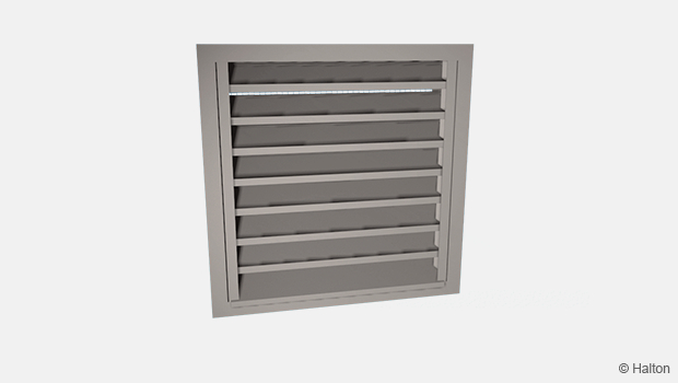
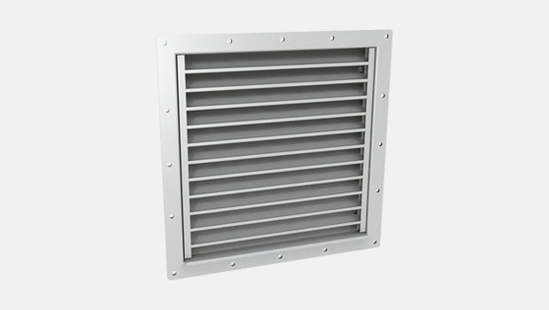
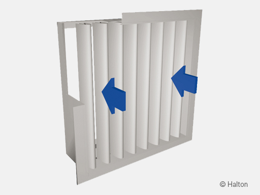
Halton USL – External louvre
An aesthetic model with electric heating. Modular construction available for large sizes and several finishing options ie, anodised or painted aluminium.
- Very effective prevention of rainwater (97%/Eurovent) and snow (75..95%) penetration due to special labyrinth construction
- Self-regulating heating cable with an operating voltage of 230 VAC
Overview
- Very effective prevention of rainwater (97%/Eurovent) and snow (75..95%) penetration due to special labyrinth construction
- Melted snow and water collection via a drip tray including a pipe connection
- Detachable front grille; electrically heated rear grille
- Self-regulating heating cable with an operating voltage of 230 VAC
- Modular construction available for large sizes
- Models available with front grille made of polyester-painted or anodized aluminum
Dimensions
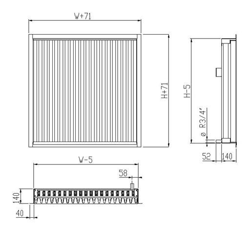
| W | H |
| 400, +50, …, 10000 | 400, +50, …, 2000 |
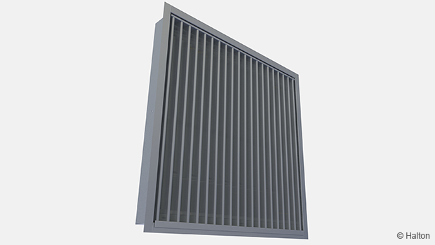
The distance between the front vertical blades is 50 mm. The free area is about 40% of the nominal opening.
Material
| Part | Material | Finishing | Note |
| Front grille | Aluminium | Polyester-painted Anodised |
Special colours available |
| Rear grille | Aluminium | – | – |
| Frame | Aluminium | – | – |
| Drip tray | Stainless steel, (AISI 316) |
– | Connection R3/4″ |
| Heating cable | – | – | Manufacturer: TYCO Raychem, type: EM2-R, self-regulating |
| Electrical connection box |
Plastic (Polypropylene) |
– | IP65 |
| Connection cable: 3 x 2.5 mm² |
Rubber (EPDM) | – | Length: 2 m |
The drip tray under the rear grille is fitted with a drain connection. The grilles are fastened to the frame with screws.
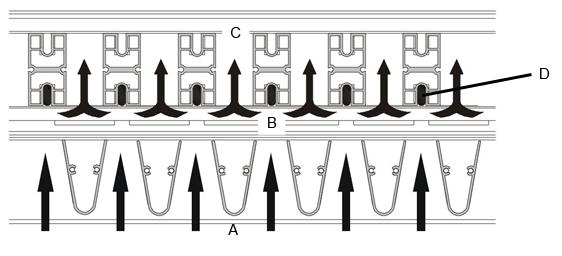
Function
Snow or water entering with the airflow is directed into the tapering slots of the front grille (A), increasing the air velocity.
The airflow is diverted into the space between the front and rear grille (B). The snowflakes hit the heated rear grille with heating cable (D), which melts the snow.
The melted water flows down the rear blades (C) to the heated drip tray, from which it is led to the drain.
When necessary, the louvre is cleaned with a soft brush.
Heating capacity
The maximum heating capacity of the rear grille and drip tray s self-regulating heating cable is 2400 W/m² when the outdoor temperature is -18 °C.
The operating voltage is 230 VAC / 50Hz.
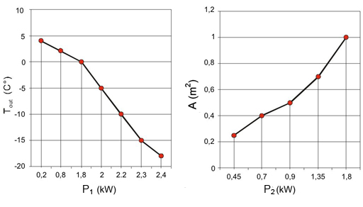
Tout (C°) = Outdoor temperature
A (m²) = Face area of louvre
P1 (kW) = Heating capacity
P2 (kW) = Heating capacity (with outdoor temp. of 0 °C)
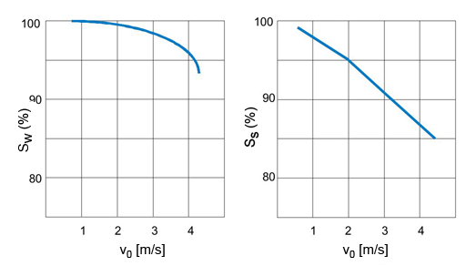
Water penetration prevention Snow penetration prevention
v0 = Face air velocity
Installation
Mounting of single Halton USL louvre
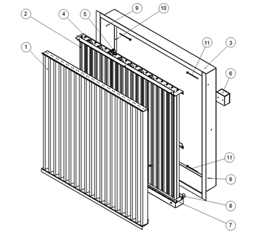
Code description
1. Front grille
2. Rear grille
3. Installation frame
4. Heating cable
5. Cable clamp
6. Cable connection box
7. Drip tray
8. Connection tap
9. Mounting hole (used for single louvre)
10. Mounting hole (used for modular louvre)
11. Mounting screw (not included in Halton delivery)
The louvre is sent from factory assembled (1-8). To be able to fasten louvre to the wall remove front (1) and rear (2) grille from frame (3). Fasten the louvre in place by screwing the installation frame (3) into a wall opening by using the mounting holes in the unit frame (9). Type of screw (11) to be selected by wall material (see drawing below: “Mounting of installation frame, single louvre”). Finally assemble the rear (2) and front (1) grille back to the installation frame (3).
The dimensions of the louvre are given as the nominal dimension. The installation opening shall be about 20 mm wider than the nominal dimension. To enable the connections, there should be an installation space of at least 100 mm behind the louvre.
Connect the drip tray drain tap to the drain pipework.
Note:
Drain pipe after the drain connection tap should be equipped with heating cable to avoid drain pipe freezing.
The duct or chamber after the louvre should be equipped with drain to remove the water or moister.

Fig.1. Mounting of installation frame, single louvre
Mounting of modular Halton USL louvre
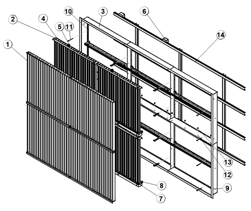
Code description
1. Front grille
2. Rear grille
3. Installation frame
4. Heating cable
5. Cable clamp
6. Cable connection box
7. Drip tray
8. Connection tap
9. Mounting hole (used for single louvre)
10. Mounting hole (used for modular louvre)
11. Mounting screw (not included in Halton delivery)
12. Mounting hole for modular connection
13. Mounting bolt for modular connection
14. Installation support for modular louvres – example structure, U-profile
(not included in Halton delivery)
– Check from Designer of structures.
Note:
In large modular installation (height > 2000 mm), the louvres shall be installed with a supporting installation construction (not included in the delivery) to be designed by Desiger of structures.
The louvre is sent from factory assembled (1-8). To be able to fasten louvre to each other and to the installation support remove front (1) and rear (2) grille from frame (3). In a modular installation, the frames of adjacent modules shall be bolted together (12,13). Assemble the rear (2) and front (1) grille to the installation frame (3).
If you are using installation support (14), connect the installation frames of modules to the installation support. Assemble then the rear (2) and front (1) grille to the installation frame (3). Finally the whole construction can be lifted up to the wall structures.
The dimensions of the louvre are given as the nominal dimension. The installation opening shall be about 20 mm wider than the nominal dimension. Because of the connections, there should be an installation space of at least 100 mm behind the louvre.
Connect the drip tray drain tap to the drain pipework.
Note:
Drain pipe after the drain connection tap should be equipped with heating cable to avoid drain pipe freezing.
The duct or chamber after the louvre should be equipped with drain to remove the water or moister.
Electrical wiring
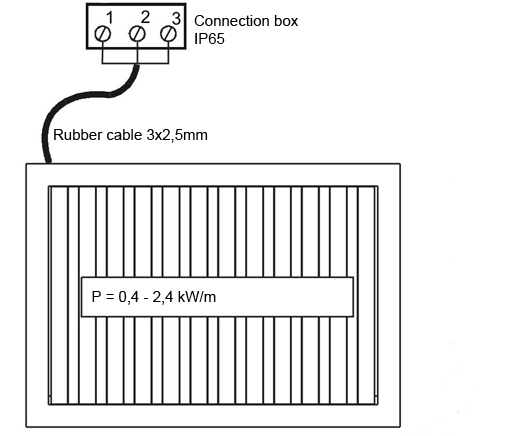
Delivery limit
Electrical connections are made with a connection box. Between the grille and connection box there is a two meter long rubber cable.
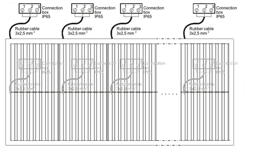
In the modular construction there is a separate connection box in each module. This must be taken into account when electrical drawings are being drafted.
Specification
The external louvre shall have a snow prevention capacity of at least 70%, and 90% for rainwater (Eurovent 2/5).
The rear grille shall be equipped with an electric self-regulating heating cable providing a maximum heating capacity of 2400 W/m2 when the outdoor temperature is -18 °C, with an operating voltage of 230 VAC.
The outdoor louvre shall be equipped with a connection box (IP 65).
The drip tray shall be provided with a drain tap R3/4″ connection.
Each louvre of a module shall have an independent connection box and drain connection.
Order Code
USL/S-W-H
S = Model
A Standard
B Louvre without heating
W = Width
400, +50, …, 10000
H = Height
400, +50, …, 2000
Other options and Accessories
FI = Finishing
NA No finishing
PN Painted
AN Anodised (colour: aluminium)
CO = Colour
G Grey
X Special colour
ZT = Tailored product
N N
Y Yes
Code example
USL/A-400-400, FI=NA, ZT=N
Downloads
"*" indicates required fields