Product / MOC
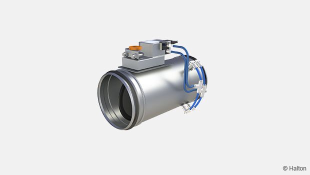
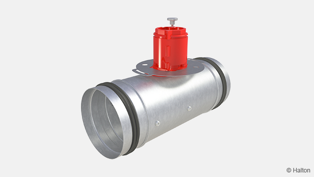
Halton Max MOC – Spjäll (VAV)
I produktutvecklingsfasen av Halton Max One har fokuset varit på att konstruera spjället minimalt påverkbart av smutsbildning.
Material och komponenter är noggrant utvalda för lång hållbarhet. Mätrören är konstruerade för att kunna hantera låga luftflöden med hög mätnoggrannhet och höga luftflöden med låg ljudalstring.
- Generell luftflödeshastighet för samtliga storlekar är 1-10 m/s med de flesta motoralternativ.
- Lämplig för både tilluft och frånluft.
- Även anpassad till Halton Vita OR operationsrums och Halton Workplace-applikationer.
Översikt
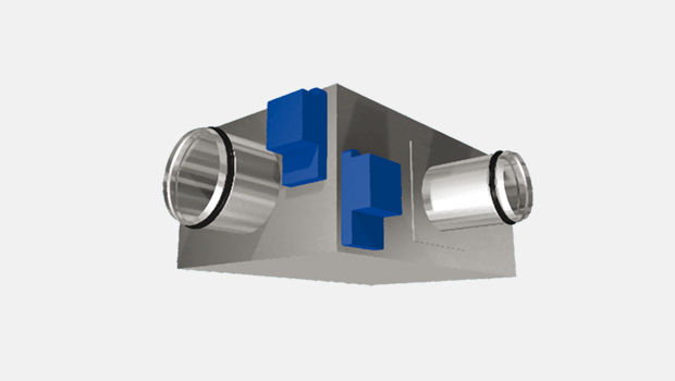
Halton Max MOC är en cirkulär luftflödesstyrningsspjäll som är utformad för mångsidig användning i ett brett utbud av VAV‑applikationer. Snabb och enkel driftsättning med fabriksinställda luftflödesgränser anpassade efter kundens specifika behov.
- Tvärställda medelvärdesmätningsrör, grundläggande ställdon, 1–10 m/s luftflöde
- Lämplig för både till- och frånluftsinstallationer
- Även anpassad till Halton Vita OR operationsrums och Halton Workplace-applikationer.
Produktmodeller och alternativ
- En modell med utvändig isolering finns som tillval
- Tätheten vid avstängning uppfyller kraven i (EN 1751), klass 4
- Höljets täthet uppfyller (EN 1751) täthetsklass C
- Flera olika anslutningsdimensioner mellan 100–630 mm
- Galvaniserat stål och rostfritt stål (EN 1.4404, AISI 316L) som alternativa material
- Flera ställdonsalternativ
- Ljuddämpare och eftervärmningsbatterier finns som tillval
Övriga produktegenskaper
- Max. differenstryck: 1 000 Pa över spjället
- Omgivningstemperatur 0–50 ºC vid drift
- Omgivande relativ luftfuktighet: < 95 %, icke-kondenserande
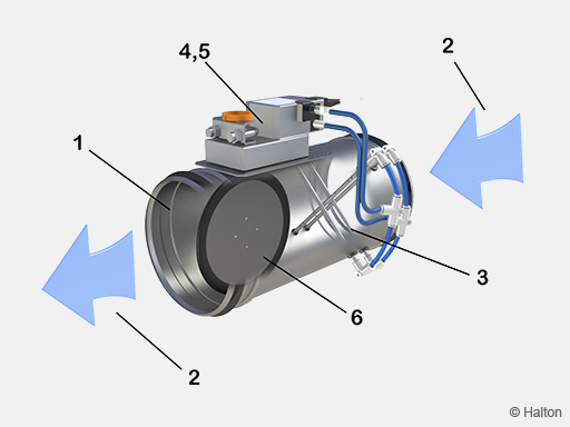
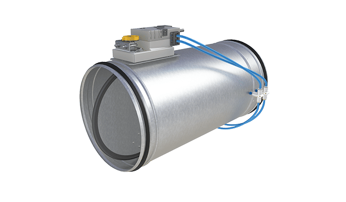
Driftsprincip
| Nr | Beskrivning |
| 1 | Spjäll |
| 2 | Luftflödesriktning |
| 3 | Mätsond |
| 4 | VAV-styrenhet för luftflöde |
| 5 | Ställdon |
| 6 | Blad |
Spjället innehåller en tvärställd sond för mätning av luftflöde, en VAV-styrenhet för luftflöde, ett ställdon och ett blad (med packning). Beroende på ställdonsmodellen är VAV-styrenheten en separat enhet eller integrerad i ställdonet.
Spjället kan fungera som både en till- eller frånluftsenhet. Spjället upprätthåller det nödvändiga luftflödet genom noggrann mätning och luftflödesstyrning, oavsett variationer i rumsförhållanden eller kanaltryck. Luftflödesmätningen baseras på ett differenstryck som skapas med hög precision av mätsondens tvärställda rör. Rören är konstruerade för hög känslighet i låga luftflöden och för låg ljudnivå i höga luftflöden.
Förändringar i rumsförhållanden kan justeras manuellt från ett slutanvändargränssnitt eller med olika sensorer såsom rörelse- eller rumstrycksensorer, termostater eller timers. Förhållandena kan också fjärrstyras från ett byggnadsstyrsystem (BMS). Styrsignalen och luftflödesmätdata från sondens rör behandlas i VAV-styrenheten. VAV-styrenheten ger ställdonet ett kommando att ändra spjällbladets läge för att hålla luftflödet vid det inställda börvärdet.
Luftflödets börvärde kan ändras mellan min- och maxvärden från rumstermostaten eller ett BMS. VAV-styrenheten kan också skicka faktiska värdesdata tillbaka till rumstermostaten. Kommunikationsprotokollet för signalen mellan rumstermostaten och VAV-styrenheten beror på ställdonsmodellen.
För mer information om tillgängliga ställdonsmodeller, se avsnittet Ställdon.
Tekniska data
Halton Max MOC luftflödesspjäll finns i två produktmodeller: G och I:
- Produktmodellerna G och I inkluderar en bladpackning för lufttät avstängning.
- Produktmodell I inkluderar en 50 mm isolering för ljuddämpning.
| Funktion | Produktmodell: G | Produktmodell: I |
| Bladpackning | x | x |
| 50 mm yttre isolering | x | |
| Täthet EN 1751, klass C och klass 4 | x | x |
| Vridmoment på ställdon, 5 Nm | Dimensioner 100-250 |
Dimensioner 100-250 |
| Vridmoment på ställdon, 10 Nm | Dimensioner 315-630 |
Dimensioner 315-630 |
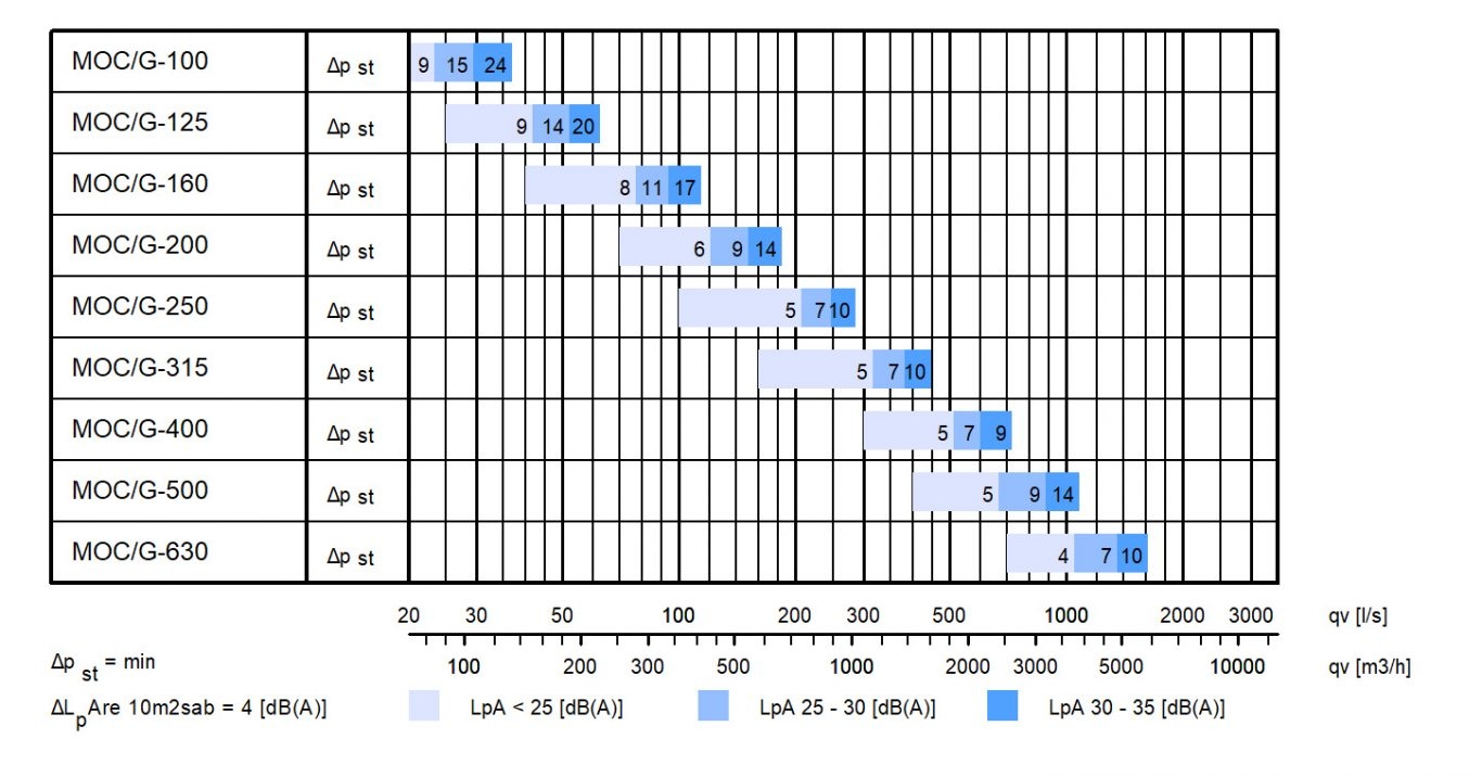
Snabbval
Luftflödesintervall för Halton Max One Circular med en lufthastighet på 1–10 m/s.
| NS [mm] | qv min – max [l/s] |
qv min – max [m3/h] |
| 100 | 8 – 79 | 28 – 283 |
| 125 | 12 – 123 | 44 – 442 |
| 160 | 20 – 201 | 72 – 724 |
| 200 | 31 – 314 | 113 – 1131 |
| 250 | 49 – 491 | 177 – 1767 |
| 315 | 78 – 779 | 281 – 2806 |
| 400 | 126 – 1257 | 452 – 4524 |
| 500 | 296 – 1964 | 707 – 7069 |
| 630 | 312 – 3117 | 1122 – 11222 |
System package
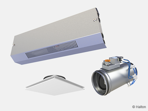
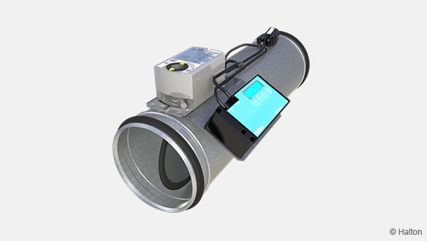
Halton Workplace WRA room automation system package for Halton Max One (MOC) airflow management damper
Halton Workplace WRA is part of the Halton Workplace solution offering.
Fig.1. Halton Jaz JDA static diffuser and Halton Max One Circular VAV damper combined with a Halton Workplace room automation controller.
Halton Workplace WRA is a controller especially designed for controlling the automation system of office spaces and meeting rooms. It is used for controlling the ventilation airflow, room temperature, and indoor air quality.
The Halton Workplace WRA room automation package consists of a controller unit and optional components depending on customer needs: a wall panel and sensors for temperature, CO2, occupancy, pressure, and condensation.
There are options available for the controller unit and wall panel, depending on the number of controls and sensors required. The Halton Workplace WRA room automation controller is always combined with other Halton products for adaptable and high-level indoor climate.
Application area
- Controlling the ventilation airflow, room temperature, and indoor air quality in office spaces and meeting rooms
- The Halton Workplace WRA room automation controller is an important part of the Halton Workplace system, controlling room units and airflow control dampers
- Overall Halton Workplace System includes:
- Room air conditioning applications with Halton Workplace WRA room automation controller:
- Active chilled beams
- Exhaust units
- VAV dampers
- Active VAV diffuser
- Room air conditioning applications with Halton Workplace WRA room automation controller:
- Halton Max MDC zone control dampers
- Halton Workplace WSO system optimiser
Key features
- Factory-tested controller and wiring, easy to install
- Pre-installed project-specific parameters, quick to commission
- Several operating modes based on occupancy, thermal comfort, and indoor air quality
- Enables fully flexible layout solutions for changing needs in office environments
- Highly energy-efficient and reliable system operation
Operating principle
The Halton Workplace WRA room automation controller operates with Variable Air Volume (VAV) dampers and active chilled beams of the Halton Workplace system. These are used for adjusting the ventilation airflow, room temperature, and indoor air quality in office spaces.
Each room unit in an office space can have its own dedicated Halton Workplace WRA room automation controller, or a single controller can control multiple room units. The Halton Workplace WRA room automation controller can automatically adjust the system according to the indoor environment level preferred by users. Each room unit having its own dedicated controller brings maximum flexibility.
Room automation: Halton Jaz JDA and Halton Max One Circular (MOC) VAV damper controlled with Halton Workplace WRA room automation controller
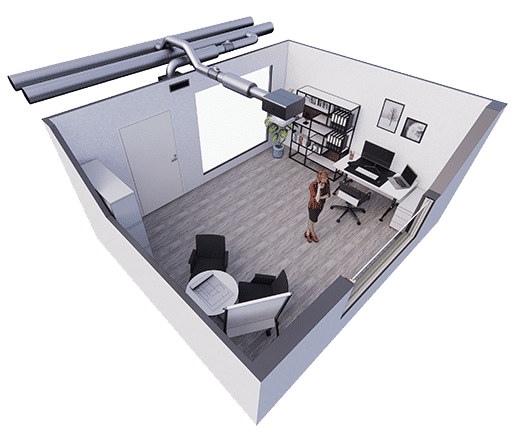
Fig.2. Halton Jaz JDA diffuser and Halton Max One Circular VAV damper, controlled with Halton Workplace WRA room automation controller in a single office room
Room automation description
In this configuration, the Halton Workplace WRA room automation controller (type DXR2.E12P-102A) controls a Halton Jaz JDA diffuser that is combined with a Halton Max One Circular VAV damper. External CO2 and occupancy sensors are installed in the room. The temperature sensor is integrated into the wall panel (type QMX3.P34). The system also includes an exhaust VAV damper and radiator heating water valve control. One Halton Workplace WRA room automation controller can individually control up to four room units, and there can be several Halton Workplace WRA room automation controllers in the room.
Design criteria for room automation
- Supply airflow control
- Exhaust airflow control
- Window switch control
- External CO2 and occupancy sensors
- Wall panel with temperature sensor and display
- Radiator heating water valve control
Schematic drawing
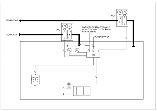
Fig.3. Schematic drawing: Halton Jaz JDA diffuser and Halton Max One Circular VAV damper, controlled with Halton Workplace WRA room automation controller
Equipment list
RCController unit
| Code | Equipment |
| FG | Airflow damper actuator |
| FC | Airflow measurement |
| H | Water valve actuator |
| OS | Occupancy sensor |
| CO2 | CO2 sensor |
| WP | Wall panel |
| TE | Temperature sensor |
| TI | Temperature display |
Wiring diagram
For the wiring diagram of similar configuration, see the product pages of the Halton Workplace WRA room automation controller.
Components and order code examples for the system
- 1 x Passive diffuser: Halton Jaz JDA
– JDA/S-125(R4) WS=NA, CO=W, ZT=N + TRI/S-125-125(N) - 1 x VAV damper: Halton Max One Circular
– MOC/G-125, MA=CS - 1 x Exhaust unit: Halton AGC Exhaust grille + Halton PRL Plenum for grilles
– AGC/N-400-100 FS=CL, ME=A, FI=PN, CO=W, ZT=N+PRL/F-400-100-160 - 1 x VAV damper: Halton Max MOC
– MOC/G-160, MA=CS - Automation package: 1 x Halton Workplace WRA room automation controller unit with related components
– WRA/MOC-E21-EV-EX4, WP=34, LC=NA, SE=NA, SW=NA, ST=NA, SL=OE, PM=NA, TC=NA, CV=NA, RV=RA, ZT=N
Note: For more information, see the product pages of the Halton Workplace WRA room automation controller.
Konstruktion och material
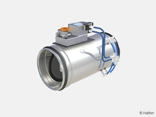
Fig.4. Halton Max One Circular (MOC), rostfritt stål (EN 1.4404 / AISI 316L)
| Komponent | Materialalternativ galvaniserat stål (beställningskod MA=CS) (order code MA=CS) |
Materialalternativ rostfritt stål (beställningskod MA=AS) |
| Hölje | Förzinkat stål | Rostfritt stål (EN 1.4404/AISI 316L) |
| Spjällblad | Förzinkat stål | Rostfritt stål (EN 1.4404/AISI 316L) |
| Axel | Förzinkat stål | Rostfritt stål (EN 1.4404/AISI 316L) |
| Bladpackning | EPDM-gummi | EPDM-gummi |
| Kanalpackningar (fastvulkade i höljet) |
1C-polyuretanhybrid | 1C-polyuretanhybrid |
| Mätsond | Aluminium | Rostfritt stål (EN 1.4404/AISI 316L) |
| Yttre isolering (modell I) |
Mineralull | Mineralull |
| Mätrör | PU-plast | PU-plast |
Styrenheter
Ett antal ställdon finns tillgängliga för olika tillämpningsbehov.
Alla ställdon inkluderar en integrerad dynamisk differenstrycksgivare med ett litet sidoluftflöde genom givarelementet. Spjället bör därför inte användas i starkt förorenade miljöer. Gränsvärden för luftflöde ställs in i fabriken.
| Ställdon | Anmärkningar | Åtdragnings-moment [Nm] |
Spjäls-storlek [mm] |
Komminikations-gränssnitt | Beställningskod (Länk till datablad) |
| EM | Analogt ställdon Tillverkare: Belimo |
5 | 100-250 | DC0..10V/2..10V | EM = LMV-D3-MF-F.1 HI (DC 0/2…10 V), 5 Nm |
| EK | Analogt ställdon Tillverkare: Belimo |
10 | 100-630 | DC0..10V/2..10V | EK = NMV-D3-MF-F.1 HI (DC 0/2…10 V), 10 Nm |
| EC | Ställdon med NFC-anslutning för mobil justering av parametrar på plats (Belimo Assistant App). Analog eller MP-bus. Tillverkare: Belimo |
5 | 100-250 | Belimo MP bus or 0..10V/2..10V |
EC = LMV-D3-MP (MP bus), 5 Nm |
| EE | Ställdon med NFC-anslutning för mobil justering av parametrar på plats (Belimo Assistant App). Analog eller MP-bus. Tillverkare: Belimo |
10 | 100-630 | Belimo MP bus or 0..10V/2..10V |
EE = NMV-D3-MP (MP bus), 10 Nm |
| ER | Ställdon med KNX Tillverkare: Belimo |
5 | 100-250 | KNX | ER = LMV-D3-KNX (KNX bus), 5 Nm |
| ES | Ställdon med KNX Tillverkare: Belimo |
10 | 100-630 | KNX | ES = NMV-D3-KNX (KNX bus), 10 Nm |
| ET | Ställdon med Modbus Tillverkare: Belimo |
5 | 100-250 | Modbus | ET = LMV-D3-MOD (Modbus RTU), 5 Nm |
| EU | Ställdon med Modbus Tillverkare: Belimo |
10 | 100-630 | Modbus | EU = NMV-D3-MOD (Modbus RTU), 10 Nm |
| EH | Analogt ställdon Tillverkare: Siemens | 5 | 100-250 | DC0..10V/ 2..10V | EH = GDB181.1E/3 (DC 0/2…10V), 5 Nm |
| EG | Analogt ställdon Tillverkare: Siemens |
10 | 100-630 | DC0..10V/2..10V | EG = GLB181.1E/3 (DC 0/2…10V), 10 Nm |
| EV | Ställdon med KNX Tillverkare: Siemens |
5 | 100-250 | KNX | EV = GDB181.1E/KN (KNX bus), 5 Nm |
| EW | Ställdon med KNX Tillverkare: Siemens |
10 | 100-630 | KNX | EW = GLB181.1E/KN (KNX bus), 10 Nm |
| EB | Ställdon med Modbus RTU (RS-485) Tillverkare: Siemens |
5 | 100-250 | Modbus | EB = GDB181.1E/MO (Modbus RTU), 5 Nm |
| EF | Ställdon med Modbus RTU (RS-485) Tillverkare: Siemens |
10 | 100-630 | Modbus | EF = GLB181.1E/MO (Modbus RTU), 10 Nm |
| T9 | Ställdon med Modbus Tillverkare: Halton | 5 | 100-250 | DC0-10V och Modbus | T9 = NSVA-MOD-5H (DC 0-10 V and Modbus RTU), 5 Nm |
| T11 | Ställdon med Modbus Tillverkare: Halton | 10 | 100-630 | DC0-10V och Modbus | T11 = NSVA-MOD-10H (DC 0-10 V and Modbus RTU), 10 Nm |
| V1* | Analogt ställdon Tillverkare: Belimo | 5 | 100-250 | DC0..10V/2..10V | V1 = LM24A-VST, (DC 0/2…10 V), 5 Nm + VRU-D3-BAC |
| V2* | Analogt ställdon Tillverkare: Belimo | 10 | 100-630 | DC0..10V/2..10V | V2 = NM24A-VST, (DC 0/2…10 V), 10 Nm + VRU-D3-BAC |
| V3* | Analogt ställdon Tillverkare: Belimo | 4 | 100-250 | DC0..10V/2..10V | V3 = LMQ24A-VST, 2.5 sec (DC 0/2…10 V), 4 Nm + VRU-D3-BAC |
| V4* | Analogt ställdon Tillverkare: Belimo | 8 | 100-630 | DC0..10V/2..10V | V4 = NMQ24A-VST, 4 sec (DC 0/2…10 V), 8 Nm + VRU-D3-BAC |
| HM | Styrenhet inkluderar ställdon med LonWorks Tillverkare: Distech |
5 | 100-250 | LonWorks | HM = ECL-VAV-S, HAV (LonWorks), 5Nm |
| HK | Modulerande ställdon från Belimo: Styrenhet LonWorks Tillverkare: Distech |
10 | 10 | LonWorks | HK = ECL-VAV-N, HAV + NM24A-SR (LonWorks), 10 Nm |
* Only for pressure control
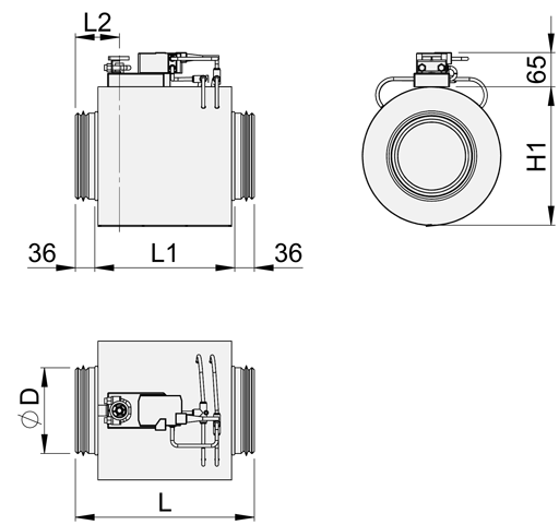
Dimensioner och vikt
Halton Max One Circular, G-modell (oisolerad ram)
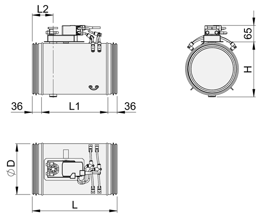
| NS | D | L | L1 | L2 | H | Vikt (kg) ** |
| 100 | 99 | 331* | 259* | 82 | 110 | 1.7 |
| 125 | 124 | 331* | 259* | 82 | 135 | 1.9 |
| 160 | 159 | 331 | 259 | 82 | 170 | 2.2 |
| 200 | 199 | 331 | 259 | 82 | 210 | 2.6 |
| 250 | 249 | 331 | 259 | 82 | 260 | 3.2 |
| 315 | 314 | 331 | 259 | 82 | 325 | 3.8 |
| 400 | 399 | 500 | 428 | 82 | 410 | 5.3 |
| 500 | 499 | 630 | 558 | 149 | 508 | 13.7 |
| 630 | 629 | 630 | 558 | 149 | 638 | 18.5 |
*) 2021-01-01 ändrades höljets längd (L=248 -> 331 mm, L1=176 -> 259 mm)
**) Ställdonet är inkluderat i vikten
Halton Max One Circular, I-modeller (isolerad ram)
| NS | D | L | L1 | L2 | H1 | Vikt (kg) ** |
| 100 | 99 | 331* | 176 | 82 | 200 | 2.2 |
| 125 | 124 | 331* | 176 | 82 | 225 | 2.7 |
| 160 | 159 | 331 | 259 | 82 | 260 | 3.6 |
| 200 | 199 | 331 | 259 | 82 | 300 | 4.4 |
| 250 | 249 | 331 | 259 | 82 | 350 | 5.3 |
| 315 | 314 | 331 | 259 | 82 | 415 | 6.8 |
| 400 | 399 | 500 | 428 | 82 | 500 | 10.2 |
| 500 | 499 | 630 | 558 | 149 | 600 | 23.6 |
| 630 | 629 | 630 | 558 | 149 | 730 | 30.8 |
*) 2021-01-01 ändrades höljets längd från 248 mm till 331 mm
**) Ställdonet är inkluderat i vikten
Specifikation
Tryckoberoende variabelt spjäll för luftflödesstyrning i till- och frånluftsinstallationer.
Konstruktion
- Spjället inkluderar en mätsond för luftflöde, luftflödesstyrenhet och ställdon.
- Kanalanslutningarna omfattar inbyggda lufttäta gummipackningar.
- Spjället inkluderar bladpackningar: styrspjällets täthet i stängt läge uppfyller klass 4 enligt standarden EN 1751 och höljets täthet uppfyller klass C enligt EN 1751.
- Spjäll med yttre ramisolering inkluderar ett 50 mm isoleringsskikt av mineralull.
Material
- Förzinkat stål, med en mätsond för luftflöde av aluminium
- Rostfritt stål, med en mätsond för luftflöde av rostfritt stål
Elektriska data
- Digital buss och/eller analog anslutning tillgänglig, beroende på ställdonet
- Analog luftflödesstyrenhet med en ingående styrsignal på 0–10 VDC eller 2–10 VDC, och utgångssignal på
0–10 VDC för återkoppling av luftflöde - Inspänning 24 VAC
Parameterinställningar
- Luftflödesgränserna förinställs på fabriken.
Tillbehör
- Ljuddämpare för minskning av buller.
- Elektriskt eftervärmningsbatteri med inbyggd värmestyrenhet. Strömförsörjning 230 VAC, mindre än 16 A. Värmaren har en inbyggd överhettningstermostat med såväl automatisk som manuell återställning samt även ett larmrelä för möjlighet till fjärrövervakning av larm. En rumstermostat krävs för att styra kanalvärmaren med en 0–10 VDC styrsignal.
- Elektriskt eftervärmningsbatteri utan inbyggd värmestyrenhet. Strömförsörjning 230 VAC (pulsbreddsmodulering). En överhettningstermostat med både automatisk och manuell återställning är inbyggd i värmaren. En rumstermostat krävs för att styra kanalvärmaren med en 0–10 VDC styrsignal.
Installation
Säkerhetsavstånd
Störningar i kanalerna som t.ex. böjar, T-stycken och ljuddämpare orsakar turbulens och ojämnt luftflöde. Detta kan leda till fluktuationer och felaktiga mätvärden.
För att säkerställa noggrannheten i luftflödesmätningen måste man ta hänsyn till det minsta säkerhetsavståndet mellan mätdonet och flödesstörningar.
För luftflödesreglerande tillämpningar är det minsta säkerhetsavståndet 1xD efter en böj och 3xD för T-stycken. Säkerhetsavståndet mellan spjället och en ljuddämpare är 2xD.
Installera enheten i kanalen så att säkerhetsavstånden och riktningen för luftflödet är som visas i följande figurer. Se projektspecifika ritningar för mer information.
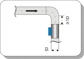
Fig.5. Böj (90º-knä)
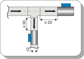
Fig.6. T-stycke
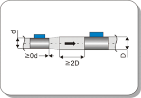
Fig.7. Med ljuddämpare
Utrymmeskrav
Tillräckligt med utrymme måste reserveras för att ge åtkomst till tillbehör under driftsättning och underhåll.
Kabeldragning
Kabeldragningen måste utföras enligt gällande bestämmelser och av behörig tekniker. En säkerhetsisolerad transformator måste användas för strömförsörjningen.
Ansvarsfördelningen mellan Halton och tredje part anges i följande exempel på kopplingsschema för en typisk tillämpning med variabel luftflödesreglering:
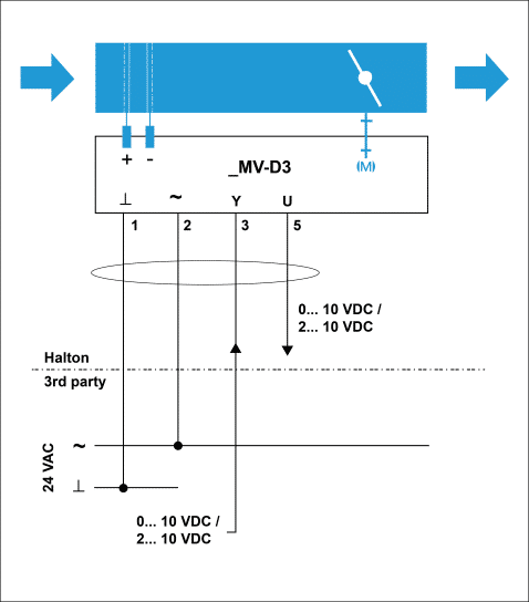
| Nr. | Nyckel |
Beskrivning |
| 1 | ⟂ | 24 VAC systemnolla |
| 2 | ~ | 24 VAC fas |
| 3 | Y | 2…10- or 0…10-VDC insignal för luftflödets börvärde |
| 5 | U5 | 2…10- or 0…10-VDC utsignal för luftflödets ärvärde |
Följande bild visar en typisk tillämpning med variabelt luftflödesreglering utan kablar.
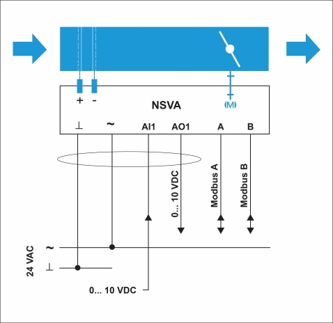
| Kabel färg | Nyckel | Beskrivning |
| Svart | ⟂ | 24 VAC systemnolla |
| Röd | ~ | 24 VAC fas |
| Grå | AI1 | Analog ingång |
| Lila | AO1 | Utgång för luftflödesåterkopplingssignal |
| Gul | A | Data in/ut A |
| Grön | B | Data in/ut B |
Driftsättning
Luftflödesstyrning
Luftflödesgränserna för Halton Max One Circular (MOC) ställs in på fabriken. Om luftflödena inte specificeras av kunden är fabriksinställningarna som standard 0 för det minsta luftflödet och det nominella värdet (Vnom) för det maximala flödet.
De nominella luftflödena i följande tabell anges för en trycknivå på 150 Pa. Gäller alla Halton Max One Circular ställdonsmodeller
| NS | Vnom [l/s] @ 150 Pa |
Vnom [m3/h] @ 150 Pa |
| 100 | 78 | 282 |
| 125 | 123 | 441 |
| 160 | 221 | 794 |
| 200 | 353 | 1270 |
| 250 | 574 | 2068 |
| 315 | 881 | 3170 |
| 400 | 1484 | 5344 |
| 500 | 2387 | 8593 |
| 630 | 3895 | 14021 |
Det verkliga luftflödet beräknas som en funktion av differenstrycket i mätsonden och mätsondens k-faktor.

| ∆pm | mätsondens differentialtryck [Pa] |
| k | k-faktor |
| qv | verkligt luftflöde [l/s] |
Ställdonen är försedda med en tryckgivare, och det går ett mycket lågt luftflöde genom styrenhetens differenstrycksgivare. En manuell manometer för mätning av differenstryck kan därför anslutas parallellt med luftflödesstyrenheten (t.ex. med T-stycken) och båda mätningarna kan ske parallellt under kontinuerlig styrning.
k-faktorer för de olika spjällstorlekarna anges i följande tabell.
| NS | k-factor [l/s] |
| 100 | 6.4 |
| 125 | 10.0 |
| 160 | 18.0 |
| 200 | 28.8 |
| 250 | 46.9 |
| 315 | 71.9 |
| 400 | 121.2 |
| 500 | 194.9 |
| 630 | 318.0 |
Tillbehör
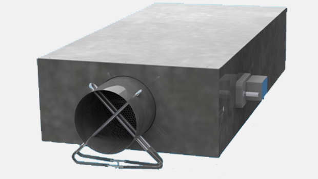
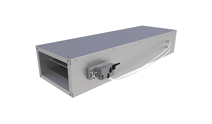
Ljuddämpare
Beskrivning
Halton erbjuder högkvalitativa rektangulära ljuddämpare med rund kanalanslutning för att minska buller i kanalen.
Ljuddämparna finns som tillbehör med följande alternativ:
- Tre längder: 600, 1 000 och 1 250 mm
- Anslutningstyper:
▪ D2=D1. Kanalens (D2) och spjällets (D1) anslutningar är lika stora.
▪ D2>D1. Kanalens anslutning (D2) är en storlek större än spjällets anslutning (D1). - Alternativa isoleringsmaterial:
▪ Polyesterfiber (PEF), testad enligt ISO 7235, EN 1751 täthetsklass C
▪ Mineralull (MW), EN 1751 täthetsklass C - Finns med eller utan renslucka för underhållsändamål
Tekniska data
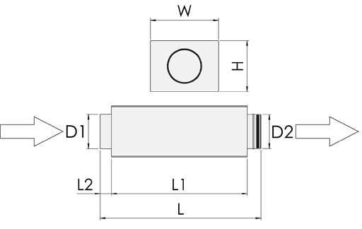
D1 är ansluten direkt till spjället med anslutning av hontyp. D2 är ansluten till kanalen med anslutning av hantyp. Bilden ovan visar tilluftsinstallationer. I en frånluftsinstallation är luftflödesriktningen från D2 till D1. Spjället är alltid anslutet till D1.
Dimensioner (mm) och vikt
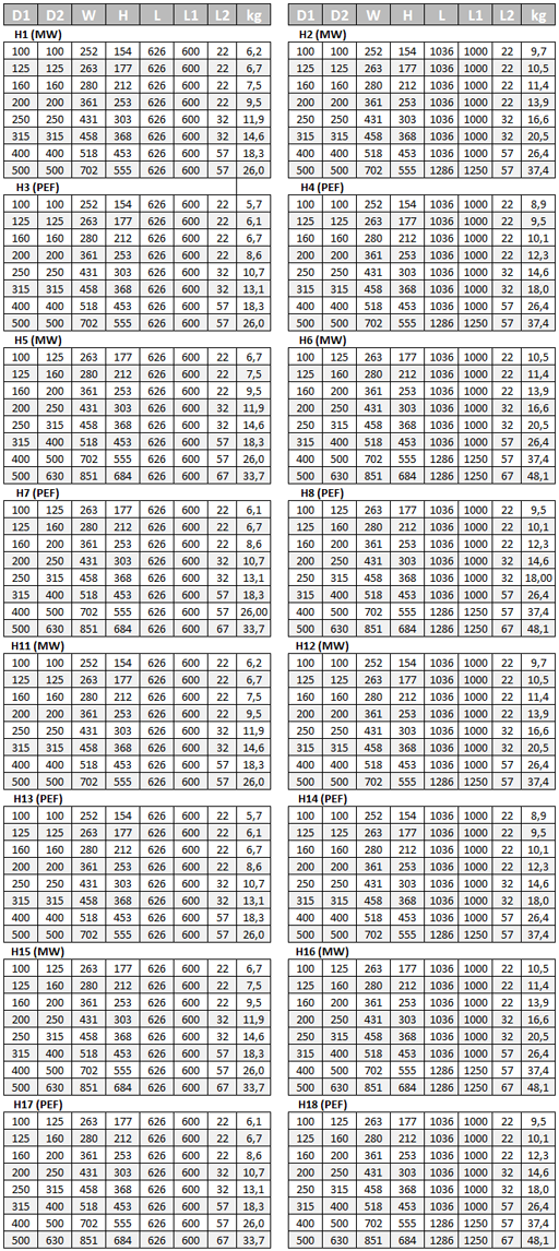
Teckenförklaring:
| Nyckel | Beskrivning |
| MW | mineralull |
| PEF | polyesterfiber |
Exempel på ljuddämpningsdata:
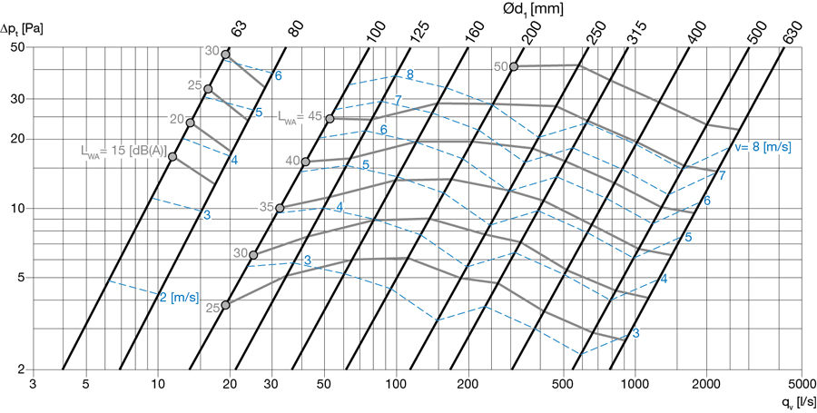
Fig.1. Ljuddämpningsdata, L = 600 mm, material = PEF
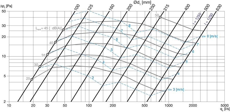
Fig. 9. Ljuddämpningsdata, L = 1 000 mm, material = PEF
Kontakta Haltons försäljningsavdelning för mer information.
Beställningskod
SA = modellkod, enligt följande koder H1–H18:
| Kod | Längd [mm] | Anslutningstyp | Isoleringsmaterial | Renslucka |
| H1 | 600 | D2=D1 | MW | Nej |
| H2 | 1000/1250* | D2=D1 | MW | Nej |
| H3 | 600 | D2=D1 | PEF | Nej |
| H4 | 1000/1250* | D2=D1 | PEF | Nej |
| H5 | 600 | D2>D1 | MW | Nej |
| H6 | 1000/1250* | D2>D1 | MW | Nej |
| H7 | 600 | D2>D1 | PEF | Nej |
| H8 | 1000/1250* | D2>D1 | PEF | Nej |
| H11 | 600 | D2=D1 | MW | Ja |
| H12 | 1000/1250* | D2=D1 | MW | Ja |
| H13 | 600 | D2=D1 | PEF | Ja |
| H14 | 1000/1250* | D2=D1 | PEF | Ja |
| H15 | 600 | D2>D1 | MW | Ja |
| H16 | 1000/1250* | D2>D1 | MW | Ja |
| H17 | 600 | D2>D1 | PEF | Ja |
| H18 | 1000/1250* | D2>D1 | PEF | Ja |
| Nyckel | Beskrivning |
| D1 | Spjällanslutning |
| D2 | Kanalanslutning |
| MW | Mineralull |
| PEF | Polyesterfiber |
| * | För storlekar ⌀D 400 eller 500. Se dimensionstabellen ovan. |
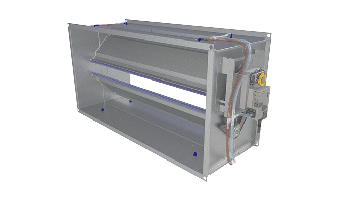
Eftervärmningsbatterier
Beskrivning
Eftervärmningsbatterier finns som tillval. Viktiga egenskaper:
- Produktmodeller
▪ Modell RM: utan inbyggd värmestyrenhet.
▪ Modell PWM: ingående styrsignal (230 VAC, pulsbreddsmodulering).
▪ Modell RC: med inbyggd värmestyrenhet, 0–10 VAC ingående styrsignal. Inbyggt larmrelä med potentialfri växlingskontakt för fjärrövervakning av larmet. Larmet utlöses av manuellt överhettningsskydd eller strömavbrott i värmaren. - Enfasvärmare med 230 VAC, mindre än 16 A
- Ökad värmarsäkerhet med två interna överhettningsskydd (automatiskt och manuellt), seriekopplade
- EN 1751, täthetsklass C
- Finns för kanaldimensioner 100–400 mm
- Effekt 600–3 000 W
Tekniska data
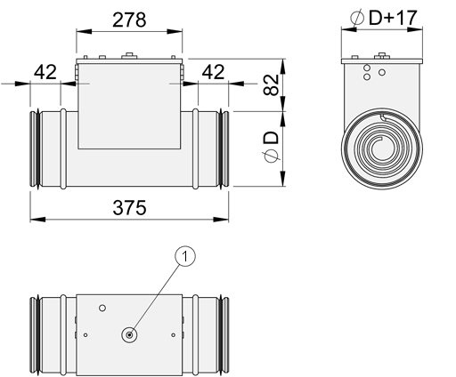
| Nyckel | Beskrivning |
| ⌀D | 100, 125, 160, 200, 250, 315, 400 mm |
| 1 | Återställning av manuellt överhettningsskydd |
Anmärkning: Eftervärmningsbatteri är inte tillgänglig på storlekar över 400 mm.
Värmaren kan installeras i vertikala eller horisontala kanaler. Säkerhetsavståndet är 2xD.
Värmaren måste alltid vara förreglad mot fläkten som blåser luft in i kanalen eller mot luftflödet som går genom värmaren. Förreglingsfunktionen är ansluten till kanalvärmarens strömförsörjning eller, om värmaren har en inbyggd värmestyrenhet (modell RC), kan den också anslutas direkt till styrenheten.
Strömmen till kanalvärmaren måste slås av när fläkten stängs av eller när luftflödet är för lågt.
När du väljer luftflödesspjäll och eftervärmningsbatteri, se till att luftflödeshastigheten är över 1,5 m/s för att garantera en korrekt styrfunktion.
Värmekapacitet med en lufthastighet på 2 m/s
| NS | Effekt [W] | qv [l/s] | qv [m3h] | dT(max) K |
| 100 | 600 | 16 | 57 | 32 |
| 125 | 900 | 25 | 88 | 31 |
| 160 | 1500 | 40 | 145 | 31 |
| 200 | 2100 | 63 | 226 | 28 |
| 250 | 3000 | 98 | 353 | 25 |
| 315 | 3000 | 156 | 561 | 16 |
| 400 | 3000 | 251 | 905 | 10 |
Värmekapacitet med en lufthastighet på 6,0 m/s
| NS | Effekt [W] | qv [l/s] | qv [m3h] | dT(max) K |
| 100 | 600 | 47 | 170 | 11 |
| 125 | 900 | 74 | 265 | 10 |
| 160 | 1500 | 121 | 434 | 10 |
| 200 | 2100 | 188 | 679 | 9 |
| 250 | 3000 | 295 | 1060 | 8 |
| 315 | 3000 | 468 | 1683 | 5 |
| 400 | 3000 | 754 | 2714 | 3 |
Kontakta Haltons försäljningsavdelning för mer information.
Beställningskod
RH=RM, RH=RC eller RH=PWM
Beställningskod
MOC-S-D; SP-MA-CU-FS-SE-TF-SA-RH-ZT
| Huvudalternativ | |
| S = Model | |
| G | Med bladpackning |
| I | Med bladpackning och isolering (50 mm) |
| D = Kanalens anslutningsdimension [mm] | 100, 125, 160, 200, 250, 315, 400, 500, 630 |
| Alternativa utföranden och tillbehör | |
| SP = Systemlösning | |
| Nej | |
| Ja | |
| MA = Material | |
| GS | Galvaniserat stål |
| AS | Rostfritt stål (EN 1,4404/AISI 316L) |
| CU = Styrenhet | |
| EM | LMV-D3-MF-F.1 HI (DC 0/2…10 V), 5 Nm |
| EK | NMV-D3-MF-F.1 HI (DC 0/2…10 V), 10 Nm |
| EC | LMV-D3-MP (MP bus), 5 Nm |
| EE | NMV-D3-MP (MP bus), 10 Nm |
| ER | LMV-D3-KNX (KNX bus), 5 Nm |
| ES | NMV-D3-KNX (KNX bus), 10 Nm |
| ET | LMV-D3-MOD (Modbus RTU), 5 Nm |
| EU | NMV-D3-MOD (Modbus RTU), 10 Nm |
| EH | GDB181.1E/3 (DC 0/2…10 V), 5 Nm |
| EG | GLB181.1E/3 (DC 0/2…10V), 10 Nm |
| EV | GDB181.1E/KN (KNX bus), 5 Nm |
| EW | GLB181.1E/KN (KNX bus), 10 Nm |
| EB | GDB181.1E/MO (Modbus RTU), 5 Nm |
| EF | GLB181.1E/MO (Modbus RTU), 10 Nm |
| T9 | NSVA-MOD-5H (DC 0-10 V and Modbus RTU), 5 Nm |
| T11 | NSVA-MOD-10H (DC 0-10 V and Modbus RTU), 10 Nm |
| V1 | LM24A-VST, (DC 0/2…10 V), 5 Nm+VRU-D3-BAC (only for pressure control) |
| V2 | NM24A-VST, (DC 0/2…10 V), 10Nm+VRU-D3-BAC (only for pressure control) |
| V3 | LMQ24A-VST, 2.5 sec (DC 0/2…10 V), 4 Nm+VRU-D3-BAC (only for pressure control) |
| V4 | NMQ24A-VST, 4 sec (DC 0/2…10 V), 8 Nm+VRU-D3-BAC (only for pressure control) |
| HM | ECL-VAV-S, HAV (LonWorks), 5Nm |
| HK | ECL-VAV-N, HAV + NM24A-SR (LonWorks), 10 Nm |
| FS = Fabriksinställda luftflödesgränser | |
| DC | Kundspecificerade inställningar |
| DS | Fabriksinställningar som standard (Vnom) |
| SE = Givare | |
| NA | Inget angivet |
| DS1 | Kanalgivare (CO2G, Kanal CO2) |
| P1 | Differenstrycksgivare (HDP-PE) |
| TF = Transformator | |
| NA | Inget angivet |
| TF1 | 230/24 transformator (35VA) |
| SA = Ljuddämpare (tillval) | Endast tillgänglig från Kausala, Finland |
| NA | Inget angivet |
| H1 | L = 600 mm; Utlopp = Inlopp; Mineralull |
| H2 | L = 1000/1250 mm; Utlopp = Inlopp; Mineralull |
| H3 | L = 600 mm; Utlopp = Inlopp; Polyesterfiber |
| H4 | L = 1000/1250 mm; Utlopp = Inlopp; Polyesterfiber |
| H5 | L = 600 mm; Utlopp > Inlopp; Mineralull |
| H6 | L = 1000/1250 mm; Utlopp > Inlopp; Mineralull |
| H7 | L = 600 mm; Utlopp > Inlopp; Polyesterfiber |
| H8 | L = 1000/1250 mm; Utlopp > Inlopp; Polyesterfiber |
| H11 | L = 600 mm; Utlopp = Inlopp; Mineralull; Renslucka |
| H12 | L = 1000/1250 mm; Utlopp = Inlopp; Mineralull; Renslucka |
| H13 | L = 600 mm; Utlopp = Inlopp; Polyesterfiber; Renslucka |
| H14 | L = 1000/1250 mm; Utlopp = Inlopp; Polyesterfiber; Renslucka |
| H15 | L = 600 mm; Utlopp > Inlopp; Mineralull; Renslucka |
| H16 | L = 1000/1250 mm; Utlopp > Inlopp; Mineralull; Renslucka |
| H17 | L = 600 mm; Utlopp > Inlopp; Polyesterfiber; Renslucka |
| H18 | L = 1000/1250 mm; Utlopp > Inlopp; Polyesterfiber; Renslucka |
| RH = Elektriskt eftervärmningsbatteri (tillval) | -> Endast tillgänglig från Kausala, Finland |
| NA | Inget angivet |
| RM | Ingen inbyggd värmestyrenhet, PWM ingående styrsignal (230 VAC, pulsbreddsmodulering) |
| PWM | Control signal input (230 VAC, pulse width modulation) |
| RC | Med inbyggd värmestyrenhet (ingående styrsignal 0–10 VAC) |
| ZT = Exempel på kod | |
| N | Nej |
| Y | Ja (ETO) |
| Tillbehör | |
| RD | Med bladpackning |
| RP | Med bladpackning och isolering (50 mm) |
| HW | Närvarogivare, vägg (HOS-OE1) |
| HC | Närvarogivare, tak (HOS-OE2) |
Exempel på kod
MOC-G-100; SP=N, MA=CS, CU=EM, FS=DC, SE=NA, TF=TF1, SA=NA, RH=NA, ZT=N
Downloads
-
Halton Max MOC – Airflow management damper (VAV)
Data
en
-
Halton Max MOC – Ilmavirtasäädin
Data
fi
-
Halton Max MOC – Régulateur à débit d’air variable (VAV)
Data
fr
-
Halton Max MOC – Spjäll (VAV)
Data
se
-
Halton Max Ultra Circular (MUC) et Halton Max One Circular (MOC) brochure
Data
French (fr) -
Halton Max MOC – Fiche technique
Data
fr_FR -
Halton Max Ultra Circular (MUC) ja Halton Max One Circular (MOC) esite
Data
Finnish (fi) -
Halton Max Ultra Circular (MUC) and Halton Max One Circular (MOC) brochure
Data
English (en) -
Halton Max MOC – Technical description
Data
English (en)
"*" indicates required fields
ABD – Automated Balancing Damper for kitchen ventilation (CE)
product
Halton BOX – VAV-spjäll
product
Halton HFD – Luftflödesspjäll
product
Halton Max MLC – Variabelflödesspjäll
product
Halton Max MOC – Spjäll (VAV)
product
Halton Max MOS – Variabelflödesspjäll
product
Halton Max MSB – Smalt VAV-spjäll
product
Halton Max MUC – Ultraljud spjäll (VAV)
product
Halton PRA – Spjäll (CAV)
product
Halton PTS – Spjäll (enbladig)
product
Halton RMC – Konstantflödesdon (CAV)
product
Halton UKV – Spjäll (VAV)
product
Halton UTK – Jalusispjäll (CAV)
product
Halton UTT – Jalusispjäll (CAV)
product