Product / MSD
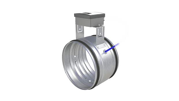
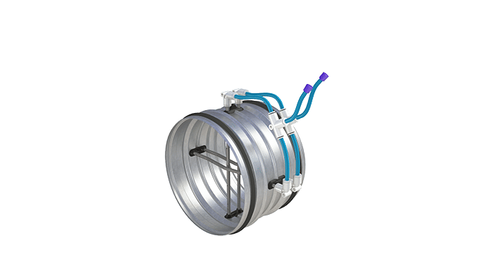
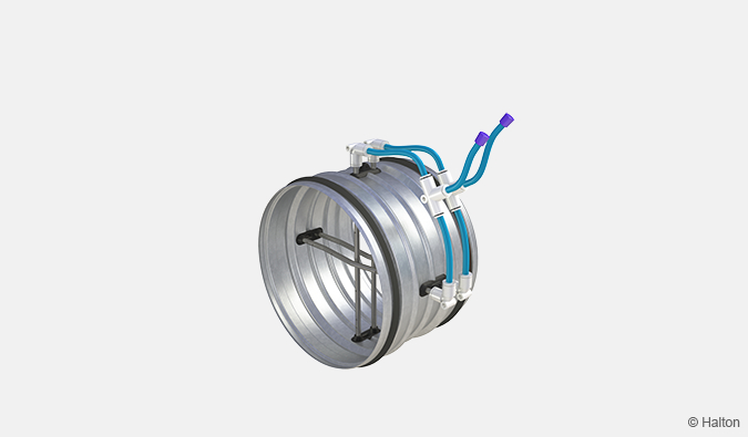
Halton MSD – Airflow measurement unit
This circular airflow measurement unit is available in many sizes. Accurate measurement based on differential pressure created by measurement probe pipes.
- Airflow measurement unit based on differential pressure created by measurement probe pipes
- Airflow transmitter installation allows 50 mm insulation
Overview
- Airflow measurement unit based on differential pressure created by measurement probe pipes
- Classification of casing leakage EN 1751 class C
- Inlet and outlet spigots have integral rubber gaskets
- Airflow transmitter installation allows 50 mm insulation
Dimensions and weight
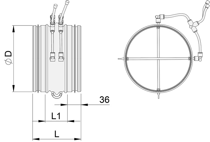
| MSD | L [mm] | L1 [mm] | ØD [mm] | Weight [kg] |
| 100 | 142 | 75 | 99 | 0.3 |
| 125 | 142 | 75 | 124 | 0.4 |
| 160 | 142 | 75 | 159 | 0.5 |
| 200 | 142 | 75 | 199 | 0.6 |
| 250 | 142 | 75 | 249 | 0.7 |
| 315 | 142 | 75 | 314 | 0.9 |
| 400 | 195 | 125 | 399 | 1.1 |
| 500 | 195 | 125 | 499 | 1.4 |
Material
| Part | Material |
| Casing | Galvanised steel |
| Measurement probe pipes | Aluminium |
| Measurement tubes | PVC and PP plastic |
| Duct gaskets | 1C-polyurethane hybrid |
Function
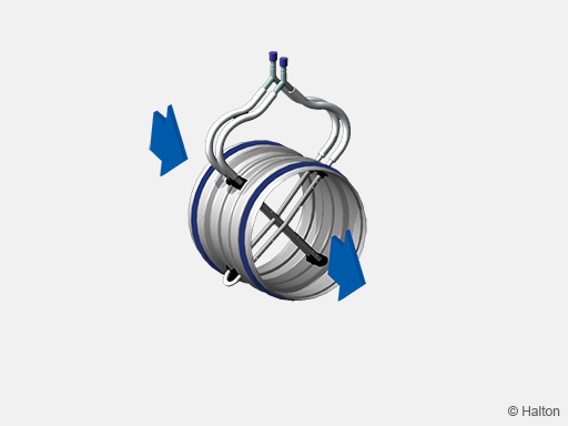
Airflow in a duct creates a pressure difference between the front and rear probes.
The corresponding airflow rate can be defined by measuring the pressure difference sensed by the two crossing sets of averaging probes.
Installation
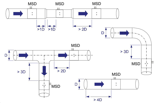
In order to ensure the accuracy of the airflow measurement the safety distances between the measurement unit and flow disturbances (e.g. bends, T-branches) have to be respected. The necessary safety distances before and after different disturbances are presented in figures below.
The figure below describes also the recommended axial orientation of measurement probes related to bends and T-branches.
Measurement
Connect the measurement tubes to the manometer and read the pressure difference. The airflow rate is calculated using the formula below or by reading the airflow rate directly from the diagram:
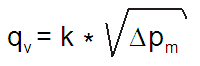
| NS | k factor |
| 100 | 5.7 |
| 125 | 9.4 |
| 160 | 17.2 |
| 200 | 27.8 |
| 250 | 43.9 |
| 315 | 72.3 |
| 400 | 127.0 |
| 500 | 200.0 |
Nominal airflow rates of Halton MSD are presented in the table below:
| NS | qv_nom |
| 100 | 70 l/s (252 m3/h) |
| 125 | 115 l/s (414 m3/h) |
| 160 | 210 l/s (756 m3/h) |
| 200 | 340 l/s (1224 m3/h) |
| 250 | 538 l/s (1937 m3/h) |
| 315 | 885 l/s (3186 m3/h) |
| 400 | 1555 l/s (5598 m3/h) |
| 500 | 2449 l/s (8816 m3/h) |
Specification
The casing of the measurement unit shall be made of galvanised steel.
The measurement probe pipes shall be made of aluminium.
The measurement unit shall have integral gaskets.
Order code
MSD-D; PT-ZT
| Main options | |
| D = Size of duct connection [mm] | 100, 125, 160, 200, 250, 315, 400, 500 |
| Other options and accessories | |
| PT = Difference pressure transmitter | |
| NA | Not assigned |
| P1 | HDE-PE |
| P2 | VRU-D3-BAC |
| ZT = Tailored product | |
| N | No |
| Y | Yes (ETO) |
Order code example
MSD-100; PT=P1, ZT=N
Downloads
"*" indicates required fields