Product / SM2
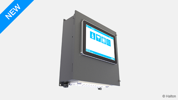
Halton Safe Management 2.0 (SM2) – Control centre
Halton Safe Management 2.0 is a fire and smoke safety system that consists of a Halton Safe Management 2.0 controller combined with several Halton Safe HSL link units that manage Halton fire dampers and smoke detectors. When a fire breaks out, the system controls the shut-off operation of fire dampers based on alarm indications from thermal fuses, smoke detection, or external alarm inputs
- Can control 200 fire dampers and 200 smoke detectors
- Enables automatic, manual, or external testing of fire damper operation
- Easy to connect with other systems
Overview
Halton Safe Management 2.0 is a fire and smoke safety system that consists of a Halton Safe Management 2.0 controller combined with several Halton Safe HSL link units that manage Halton fire dampers and smoke detectors. When a fire breaks out, the system controls the shut-off operation of fire dampers based on alarm indications from thermal fuses, smoke detection, or external alarm inputs.
The Halton Safe Management 2.0 controller enables automatic, manual, or external testing of fire damper operation, including test reporting. You can set the controller to shut off the fans during testing and in a fire situation.
The Halton Safe Management 2.0 controller has outputs for remote fire and service alarm indications. It also has local alarm indication for fire and service alarms. You can connect the controller to the Building Management System (BMS) via BACnet/IP.
Applications
- Controlling fire dampers and smoke detectors in buildings.
Key features
- Can control 200 fire dampers and 200 smoke detectors
- Enables automatic, manual, or external testing of fire damper operation
- Easy to connect with other systems
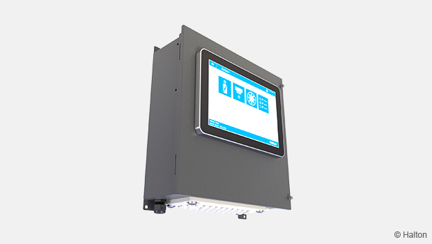
- 10.1″ graphical touch screen
- BACnet/IP communication to Building Management System (BMS)
Operating principle
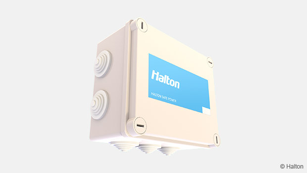
You can extend the Halton Safe Management 2.0 system modularly with up to 50 pieces of Halton Safe HSL link units to which the fire dampers and smoke detectors are connected. 1–4 fire dampers and 1–4 smoke detectors can be connected to each Halton Safe HSL link unit. The link unit’s internal control logic is used in managing the fire dampers and smoke detectors. An internal communication bus is used between the Halton Safe Management 2.0 controller and Halton Safe HSL link unit. Halton Safe HSP power units provide power to Halton Safe HSL link unit.
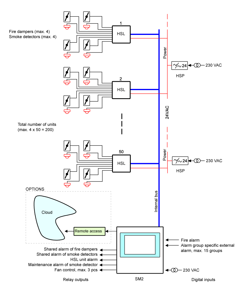
Fig.1. Overview of the Halton Safe Management 2.0 system
Features and options
Alarm groups
Fire dampers and smoke detectors can be clustered into as many as 15 alarm groups, enabling the system to respond to a fire alarm by closing only those fire dampers that are in the affected fire compartment. You can set each fire damper or Halton Safe Link unit to function as an independent alarm group.
Testing
The fire dampers can be set to be automatically tested at a specified time, or you can start a test manually. The system creates a report of the tests carried out, indicating the functionality of each fire damper. If the actuator of a fire damper is not functioning properly, the system activates a service alarm.
System use
The system can be used with the 10.1″ graphical touch screen user interface. Optionally, you can also have a remote connection (4G, for example) that enables you to use the system through a web browser.
Safety functions
If the power supply to the system fails or there is a fault in the Halton Safe Management 2.0 controller, the Halton Safe Link units continue operating independently. If a Halton Safe HSL link unit loses its operating voltage because of a fire or because the power supply to the system fails, the fire dampers are closed by a spring. It is also possible to connect a backup battery to the Halton Safe Management 2.0 controller to make sure the system can relay alarms also in case the power supply to the system fails.
Specification
Fire and smoke safety system for up to 200 fire dampers and 200 smoke detectors.
- The main controller can be modularly extended with fire damper link units, to which fire dampers and smoke
detectors are connected. - An internal communication bus is used between the main controller and the fire damper link units.
- The operating voltage of the main controller is 230 V AC.
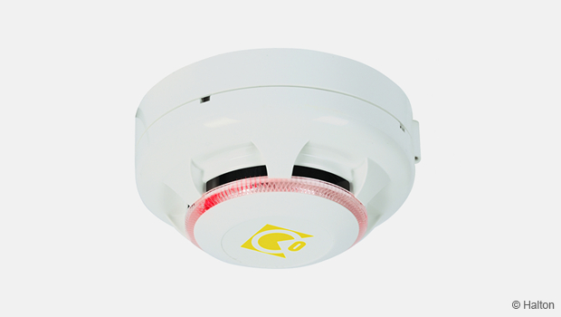
- Smoke detectors for ductwork or room installation are used.
Control and grouping
- 1–4 fire dampers and 1–4 smoke detectors can be connected to each fire damper link unit.
- Fire damper link unit uses its internal control logic in managing the fire dampers and smoke detectors.
- Each fire damper or fire damper link unit can be set to function as an independent alarm group.
- Fire dampers and smoke detectors can be clustered into as many as 15 alarm groups, enabling the system to respond to a fire alarm by closing only those fire dampers that are in the affected fire compartment.
Testing and operation
- The damper test function is triggered by an automatic function at adjustable intervals, manually, or from an external system.
- The system shuts off the fans for the duration of the test cycle.
- The system creates a report of the tests carried out.
- The test report indicates the functionality of each fire damper. If the actuator of a fire damper is not functioning properly, the system sends a service alarm.
- The system is used with a 10.1″ graphical touch screen user interface.
- The system can be equipped with an optional remote connection (4G, for example) that enables the user to use the system through a web browser.
Safety functions
- If the power supply to the system fails or there is a fault in the main controller, the fire damper link units continue operating independently.
- If a fire damper link unit loses its operating voltage because of a fire or because the power supply to the system fails, the fire dampers are closed by a spring.
- In the event of a fire, the system closes all the fire dampers and shuts off the ventilation fans in the common service area.
- A fire alarm is activated based on alarm indications from thermal fuses, smoke detection, or external alarm inputs.
Design information
Design considerations
When designing a fire safety system, consider the following:
How are dampers controlled in an alarm situation: should all dampers close or are dampers defined in different alarm groups?
- All dampers close when there is a fire alarm.
- Using alarm groups, only those dampers close that are in the affected fire compartment. Other alarm groups stay open until there is a new fire alarm or a common fire alarm.
How does the damper status affect the fans?
- If there are several alarm groups, a certain alarm group can affect the fan running permissions, whereas in another alarm group, the fans can keep running, even when there is a fire alarm.
- How is the communication between different systems taken care of?
- A traditional relay-based system can be used, where alarm information between systems goes through separate wires.
- A BACnet/IP interface can be included for communication with other systems, for example, for sending damper status information to the Building Management System (BMS).
Commissioning
When designing a Halton Safe Management 2.0 system, take into account the following information related to commissioning and maintenance:
The project-specific parameters of the controller are configured during system commissioning on site. Wiring needs to be checked before the system start-up.
The Halton Safe Management 2.0 controller addressing is pre-set at the factory. If addressing needs to be changed later or if any system parameters need to be modified, it can be done from the controller user interface.
Halton Safe HSL link unit addressing is defined during system commissioning. Each Halton Safe HSL link unit must have a unique address. The addresses are defined by using the DIP switches in the Halton Safe HSL link units.
For more detailed commissioning and maintenance instructions, see Halton Safe Management 2.0, Installation, commissioning, operating and maintenance guide.
System selection examples
Halton Safe Management 2.0 controller controlling several alarm groups
Description
In this configuration, the Halton Safe Management 2.0 controller controls three alarm groups. Each alarm group includes several Halton Safe HSL link units to which the fire dampers are connected. The building has a separate fire alarm system that it is connected to the external fire alarm inputs of the Halton Safe Management 2.0 controller with cables. The Halton Safe Management 2.0 controller is connected to the Building Management System (BMS) with cables. The separate fire alarm system is also connected to the BMS. The Halton Safe Management 2.0 controller gives the running permission to the Air Handling Unit (AHU).
When the fire alarm system sends an alarm to the Halton Safe Management 2.0 controller or the thermal fuse of a fire damper gives an alarm indication the Halton Safe Management 2.0 controller closes certain alarm groups and forwards the status of the alarm groups to the BMS system. Depending on the alarm groups in question, the Halton Safe Management 2.0 controller keeps the AHU running or stops it. The fire alarm system also sends an alarm indication to the BMS.
Design criteria
- Building has several fire groups
- One Halton Safe Management 2.0 controller
- Separate fire alarm system
- A relay-based system with cable connections is used for communication between different systems
- Halton Safe Management 2.0 gives the running permission to AHU
Schematic drawing

Fig.2. Schematic drawing of one Halton Safe Management 2.0 controller controlling several alarm groups
| Code | Equipment |
| SM2 | Halton Safe Management 2.0 controller |
| HSL | Halton Safe Link unit |
| HSP | Halton Safe Power unit |
| AHU | Air Handling Unit |
| M | Fire damper actuator |
Example order code
- 1 x Halton Safe Management 2.0 controller
- Code example: SM2/C
- 7 x Halton Safe HSL link unit
- Code example: HSL/L
- 3 x Halton Safe HSP power unit
- Code example: HSP/P
- 1 x System commissioning
- 27 x Halton fire damper
Halton Safe Management 2.0 system with smoke detectors controlling several alarm groups
Description
In this configuration, the Halton Safe Management 2.0 controller controls three alarm groups. Each alarm group includes several Halton Safe Link units to which the fire dampers and smoke detectors are connected. The Halton Safe Management 2.0 controller is connected to the Building Management System (BMS) with cables.
When a smoke detector or the thermal fuse of a fire damper gives an alarm indication, the Halton Safe Management 2.0 controller closes certain alarm groups and forwards the status of the alarm groups to the BMS system.
Design criteria
- Several alarm groups in the building
- One Halton Safe Management 2.0 controller
- Smoke detectors included in the system
- Ethernet cable and BACnet/IP bus used for communication between different systems
Schematic drawing

Fig.3. Schematic drawing of Halton Safe Management 2.0 system with smoke detectors controlling several alarm groups
| Code | Equipment |
| SM2 | Halton Safe Management 2.0 controller |
| HSL | Halton Safe HSL, link unit |
| HSP | Halton Safe HSP, power unit |
| AHU | Air Handling Unit |
| M | Fire damper actuator |
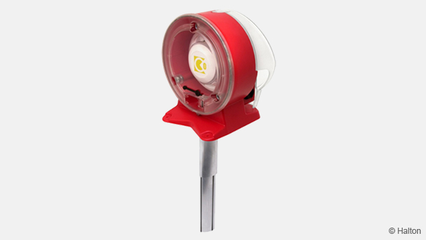
| SD | Smoke detector, type: Halton Safe HSD, smoke sensor – duct |
Example order code
- 1 x Halton Safe Management 2.0 controller
- Code example: SM2/C
- 5 x Halton Safe Link unit
- Code example: HSL/L
- 3 x Halton Safe Power unit
- Code example: HSP/P
- 1 x System commissioning
- 18 x Halton fire damper
- 9 x Halton Safe Smoke Sensor Duct
- Code example: HSD/D1
Structure and components
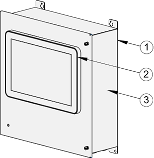
Fig.4. Structure of Halton Safe Management 2.0 controller
| No. | Part | Details |
| 1 | Controller case | Painted metal, grey |
| 2 | User interface | Touch screen |
| 3 | Label | Product info |
Dimensions and weight
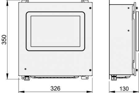
Fig.5. Dimensions of Halton Safe Management 2.0 controller
Weight
4.1 kg
Order code
SM2/S; ZT
M = Model
S Standard
Other options and accessories
ZT = Tailored product
N No
Code example
SM2/S, ZT=N
Downloads
-
Halton Safe Management 2.0 (SM2) – Control centre
Data
en
-
Halton Safe Management 2.0 (SM2) – Ohjauskeskus
Data
fi
-
Halton Safe Management 2.0 (SM2) – Installation, commissioning, operating and maintenance guide
Data
en_GB -
Halton Safe Management 2.0 (SM2) – Asennus-, käyttöönotto-, käyttö- ja huolto-opas
Data
fi
"*" indicates required fields