Product / ULA
Overview
- Suitable as supply or exhaust air valve.
- Wall or ceiling installation.
- Adjustable airflow rate.
- Ability to measure airflow rate.
- Attenuates duct noise.
- Flow pattern can be directed to one direction.
- Installation without an installation frame directly into ductwork or with a separate installation frame.
Product models and accessories
- Model with installation frame.
- Protection ring for protecting the surfaces from smudging.
- Extension part for detaching the valve from surfaces.
Quick selection
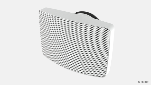
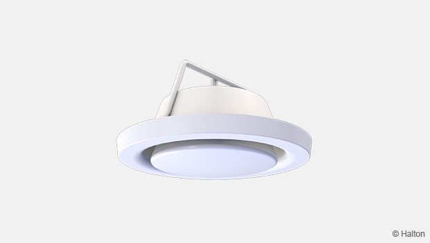
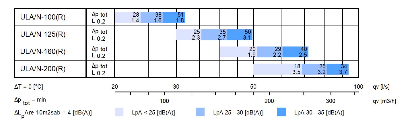 Fig.1. Halton ULA, radial jet
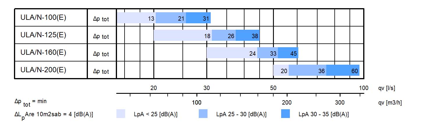
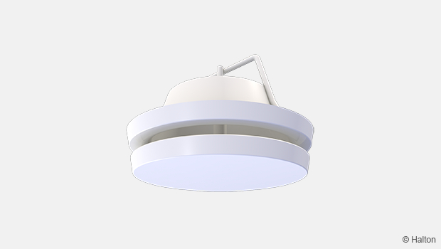
Fig.2. Halton ULA, exhaust
Dimensions and weight
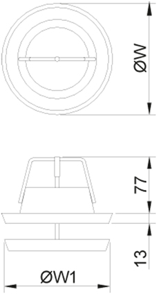
| NS [mm] |
ØW [mm] |
ØW1 [mm] |
Weight [kg] |
| 100 | 140 | 133 | 0.4 |
| 125 | 165 | 155 | 0.5 |
| 160 | 200 | 189 | 0.6 |
| 200 | 251 | 240 | 0.9 |
Material
| Part | Material | Note |
| Collar | Steel | – |
| Front panel | Steel | – |
| Attenuation panel | Polyethylene | – |
| Sector plate | Polyethylene | – |
| Gasket | Polyurethane | – |
| Finishing | Painted, white (RAL 9003 /30%) | Special colour available |
Accessories
| Accessory | Code | Description |
| Cover plate | CS | For protection of the surfaces from smudging and for directing the air jet in a grid-structured ceiling |
| Extension part | EP | Extension part for detaching the valve from the surface/ standard height 50 mm |
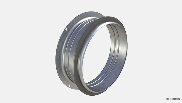
| Installation frame | LF | Installation frame without gasket/ height 50 mm |
| Installation frame | GF | Installation frame with gasket/ height 50 mm |
| Installation frame | DF | Installation frame with duct dimensions can be installed directly to duct parts such as bending or T-branch etc |
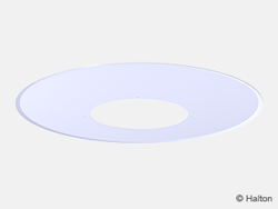
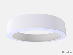
Fig.1. Cover plate (CS) Fig.2. Extensions part (EP)
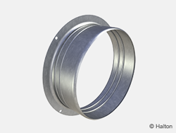
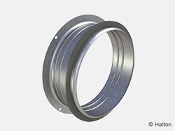
Fig.3. Installation frame (LF) Fig.4. Installation frame (GF)
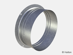
Fig.5. Installation frame (DF)
Function
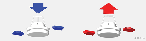
Supply Exhaust
In supply air application in the desired flow pattern is directed using an internal sector plate.
Pressure loss and airflow rate are dependent on both the flow pattern adjustment and position of the front panel.
The valve attenuates duct noise.
The desired pressure loss and airflow rate can be adjusted in an exhaust air application, by removing the sector plate and adjusting the front panel position.
Installation
The collar of Halton ULA is installed either directly into the end of a duct with fixing springs or alternatively with the aid of a separate installation frame (LF, GF or DF).
The supply air valve can be installed in contact with the ceiling or wall surface, with or without a protection ring (CS), or with an extension part (EP).
Protection ring (CS)
The CS protection ring protects the surface from smudging and can also be used for directing the air jet in an open grid-structured ceiling installation.
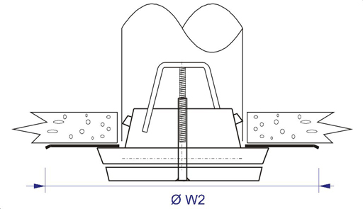
| NS | Ø W2 |
| 100 | 290 |
| 125 | 315 |
| 160 | 350 |
| 200 | 400 |
Extension part (EP)
The EP extension part allows the valve to be suspended from the ceiling surface, allowing the supply air jet to be directed clear of a nearby obstacle.
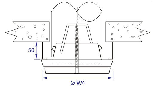
| NS [mm] |
Ø W4 [mm] |
| 100 | 150 |
| 125 | 175 |
| 160 | 210 |
| 200 | 260 |
Installation hole in hollow core slabs
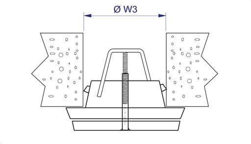
| NS [mm] |
Ø W3 [mm] |
| 100 | 96-101 |
| 125 | 121-126 |
| 160 | 155-161 |
| 200 | 195-201 |
Adjustment
In the supply application the sector plate is positioned prior to airflow direction. In an exhaust application the sector plate is not used, yet the spring shall be conserved.
The Halton ULA valve is adjusted by rotating the front panel. Measure the opening (A) position (in mm) of the front panel.
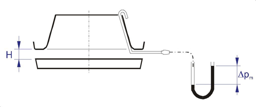
Set a probe inside the valve and measure the differential pressure with a manometer. The airflow rate is calculated using the formula below.
After adjustment, lock the front panel with the locking nut.
Servicing
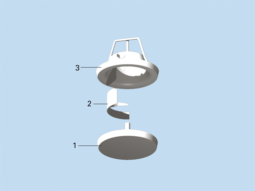
Key
1. Front panel
2. Sector plate
3. Collar
Loosen the valve from duckwork and unscrew the front panel (1) from the collar (3) for cleaning. Remove the sector plate (2) by pulling gently to detach the spring. Clean the components with a damp cloth, instead of immersing in water. Reassemble in reverse order after cleaning.
Specification
The supply and exhaust valve shall have a detachable front panel and collar made of painted steel, with a white (RAL 9003) standard colour.
The collar shall have fixing springs and comprise a sealing gasket to be fixed directly to the duct. The front panel shall have a sound attenuation panel to reduce duct noise.
When used for supply, the desired flow pattern shall be adjusted by rotating the front panel and using the internal sector plate (180° or 360°).
Order code
ULA/S-D; CO-ZT
S = Model
N Standard with fastening springs
A For installation with a separate frame
D = Duct connection size [mm]
100, 125, 160, 200
Other options and accessories
CO = Colour
SW Signal white (RAL 9003)
X Special colour (RAL xxxx)
ZT = Tailored product
N No
Y Yes (ETO)
Sub products
CS Cover plate (ULA)
EP Extension part
DF Installation frame for duct parts
GF Installation frame with gasket
LF Installation frame without gasket
Order code example
ULA/N-100, CO=SW, ZT=N
Downloads
"*" indicates required fields