Product / ZRE
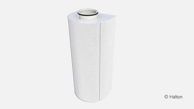
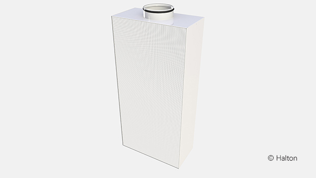
Halton Zen ZRE – Displacement ventilation unit
Rectangular displacement unit, excellent for general use.
- Capacity for wide supply airflow range
- Low velocity air is supplied horizontally at the floor level
Overview
- Capable of a large supply airflow range
- Uniform supply air distribution is achieved through small perforations, providing optimal conditions in the immediate proximity of the diffuser.
- Low velocity air is supplied horisontally at the floor level.
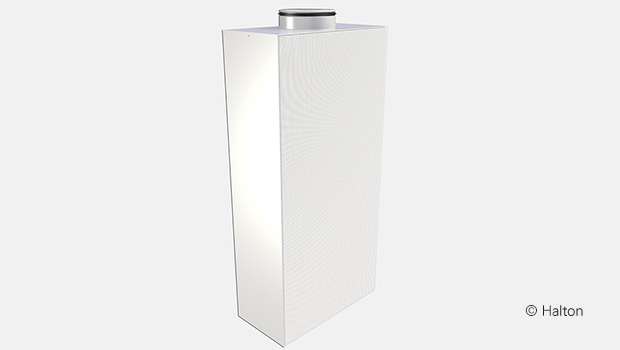
- The unit can also be installed flush with the wall.
- Ceiling installation available as tailored solution. Please contact sales..
- The detachable front panel and metallic internal structure enable cleaning of the unit and ductwork.
- Circular or rectangular duct connections available, with integrated rubber gasket at the top/bottom, or circular connections on the side or back.
Product models and accessories
- Optional duct connection locations
- Stainless steel (AISI 316L) design
- Model with thick front panel (1.5 mm)
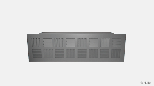
- Duct cover
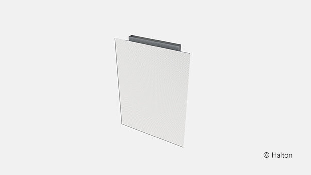
- Installation base
- Installation frame
Quick selection
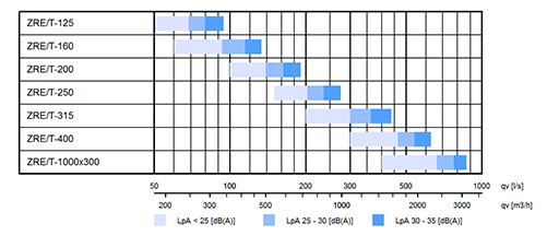
Fig.1. Halton Zen ZRE, top connection
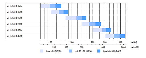
Fig.2. Halton Zen ZRE, left and right connection
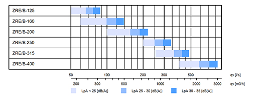
Fig.3. Halton Zen ZRE, back connection
Dimensions and weight
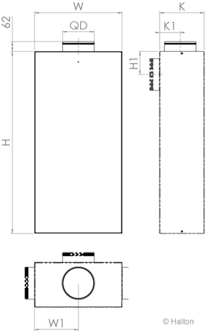
| NS [mm] |
W [mm] |
H [mm] |
W1 [mm] |
H1 [mm] |
K [mm] |
K1 [mm] |
ØD [mm] |
Weight [kg] |
| 125 | 550 | 540 | 275 | 125 | 240 | 110 | 124 | 10.7 |
| 160 | 550 | 540 | 275 | 125 | 240 | 110 | 159 | 10.7 |
| 200 | 550 | 1140 | 275 | 145 | 280 | 130 | 199 | 20.0 |
| 250 | 660 | 1350 | 330 | 170 | 330 | 155 | 249 | 28.3 |
| 315 | 830 | 1600 | 415 | 200 | 400 | 188 | 314 | 41.0 |
| 400 | 950 | 2000 | 475 | 245 | 480 | 230 | 399 | 58.0 |
| *1000×300 | 1150 | 2000 | 575 | – | 380 | 180 | 998×298 | 62.4 |
* Size 1000×300 available only with top connection
- AB/ZRE installation base:
Height = 100 mm - SB/ZRE installation base, high model:
Height = 200 mm, W=W+120, K=K+60
Material
| Part | Material | Note |
| Front panel | Perforated galvanised steel | Stainless steel (AISI 316L) as option |
| Polyester-epoxy painted White (RAL 9003 30% gloss) |
Special colours available | |
| Casing | Galvanised steel | Stainless steel (AISI 316L) as option |
| Flow equalisation element | Galvanised steel | Stainless steel (AISI 316L) as option |
| Pressure measurement pipe | Plastic | – |
| Spigot | Galvanised steel | Stainless steel (AISI 316L) as option |
| Gasket | Rubber compound | – |
| Duct cover | Galvanised steel | – |
| Polyester-epoxy painted White (RAL 9003/30% gloss) |
Special colours available | |
| Installation base | Galvanised steel | – |
| Polyester-epoxy painted White (RAL 9003/30% gloss) |
Special colours available | |
| Cover list | Galvanised steel | Stainless steel (AISI 316L) as option |
| Polyester-epoxy painted White (RAL 9003/30% gloss) |
Special colours available |
Accessories
| Accessory | Code | Description | Note |
| Duct cover (1) | DC | Standard lengths 500 / 1000 / 1500 / 2000 mm |
– |
| Installation base (2) | AB | Standard height 100 mm | – |
| Installation base | SB | Standard height 200 mm / Dimensions = unit size + 60 mm |
High (store) model |
| Cover list | CL | Cover list for fixing into wall or ceiling | – |
Product models
- Duct cover (DC) made of perforated steel (same material as ZRE unit)
- Construction made of stainless steel (AISI 316L)
- Thicker front panel (1.5 mm)
- Optional duct connection sides (left, right or back – see images below)
Note: Size 1000×300 available only with top connection
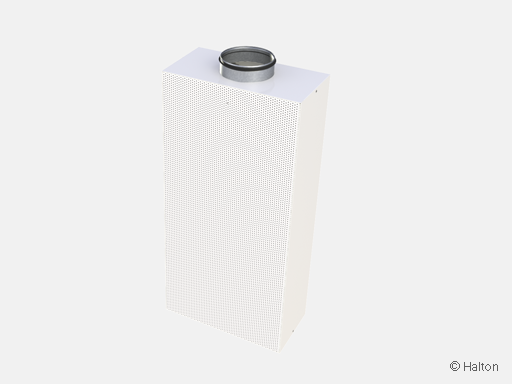
Fig.4. Connection from top (ZRE/T)
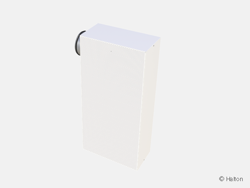
Fig.5. Connection from left (ZRE/L)
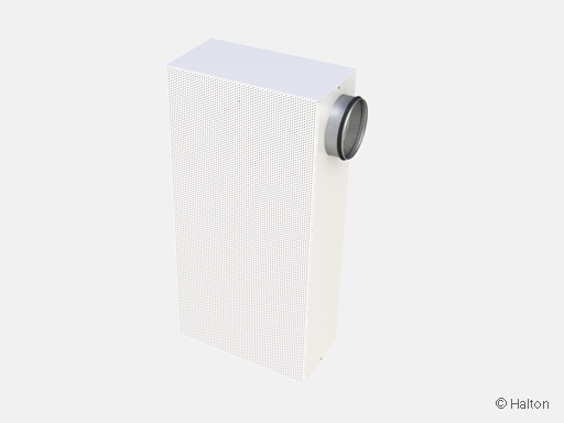
Fig.6. Connection from right (ZRE/R)
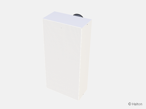
Fig.7. Connection from back (ZRE/B)
Function
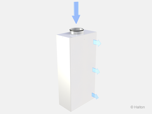
Air is supplied into the space uniformly through the front panel of Halton Zen ZRE, generally at a slightly lower temperature than the room air. The supply air flows down to the floor level, before gradually pervading the occupied zone at a low velocity. Finally the convection of warm surfaces causes the air to rise out of the occupied zone. The low velocity flow pattern is directed forwards.
The non-clogging unit can be easily opened and cleaned.
Halton PRA or Halton PTS/C can be used as an airflow adjustment damper in round duct sections. The safety distance for reliable air flow measurement from the displacement unit is 5 duct dimensions between displacement unit and air flow adjustment damper.
If air flow adjustment damper is installed closer to the displacement unit (minimum distance about 3 duct dimensions), supply air throw pattern is correct, but air flow measurement result will not be accurate. When installing air flow adjustment damper close to the displacement unit (minimum 3xD), attenuator could be needed between the damper and the displacement unit.
Note: The flow pattern data has been defined for a floor level installation.
Installation
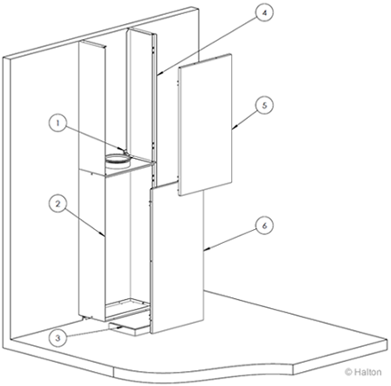
Perform the installation for Halton Zen Rectangular in the following order:
A) Installation without base:
Fix mounting brackets(4 places) to the unit (1).
Position the unit (2) against the wall and secure with mounting brackets
(included in delivery).
Installation with base:
Fix the base (6) onto the floor and fix the unit (2) onto that.
Secure with mounting brackets on top (1) (2 places)
B) Fix duct cover sides (4) onto the wall between the unit and ceiling with
screws (not included in delivery) through cover.
C) After installation of the ductwork, install the front plate of the duct cover (5).
D) When multiple sections of duct covers are used, secure them with screws
(not included in delivery).
E) Install front plate of the low velocity unit (6).
Ceiling installation available as tailored solution. Please contact sales.
Adjustment
The supply flow rate is determined by measuring the differential pressure from the measurement nipple with a manometer.Use a measurement probe thin enough fit into the nipple. Then use tape or another gasket to create a seal in the nipple in order to get an accurate reading .
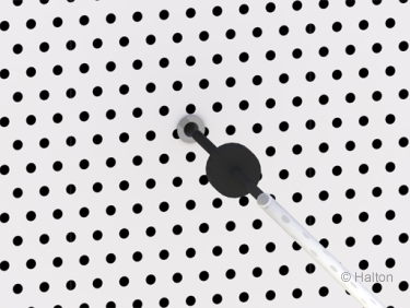
The flow rate is calculated by using the formula below:
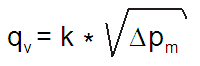
The values of k factor for formula
(D = duct diameter; L/R, T, B = location of duct connection)
| D [mm] |
k factor Left/Right |
k factor Top |
k factor Back |
| 125 | 10.9 | 11.1 | 12.1 |
| 160 | 15.6 | 16.2 | 17.1 |
| 200 | 27.3 | 26.9 | 29.1 |
| 250 | 44.3 | 42.9 | 47.6 |
| 315 | 67.9 | 66.1 | 74.2 |
| 400 | 105.7 | 100.7 | 118.1 |
| 1000X300 | – | 166.3 | – |
Servicing
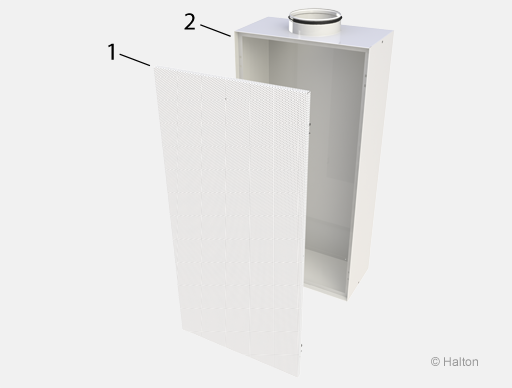
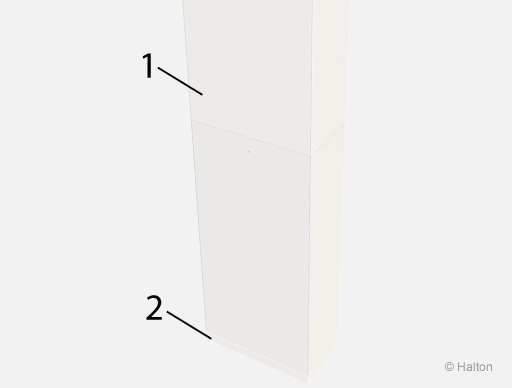
Key
1. Front panel
2. Casing
Open the front panel (1) by carefully pulling the spring connections out.
If required, the flow equalization plate can be detached.
Wipe the parts with a damp cloth. Do not immerse in water.
Reassemble after cleaning in reverse order.
Specification
The Halton Zen ZRE displacement ventilation supply unit is made of galvanised steel, polyester-epoxy-painted with a white (RAL 9003) colour.
The unit has a robust maintenance-free, non-clogging design.
The unit is comprised of a detachable, perforated front panel, an internal flow equalization plate, and casing.
The unit has a circular or rectangular duct connection on at the top, or a circular connection on the left/right side or back depending on where the unit is located.
Mounting brackets are included in the delivery, screws not.
Options
The unit is equipped with a duct cover and/or installation base, where required.
The front panel of the unit is available of 1.5mm thick galvanised steel for demanding spaces.
Order Code
ZRE/S-D; MA-TP-CO-ZT
S = Location of duct connection
T Top
L Left
R Right
B Back
D = Size of duct connection [mm]
125, 160, 200, 250, 315, 400
1000 x 300 (only top connection)
Other options and accessories
MA = Material
CS Steel
AS Stainless steel (AISI 316L)
TP = Front panel thickness 1.5 mm
N No
Y Yes
CO = Colour
SW Signal white (RAL 9003)
X Special colour (RAL xxxx)
ZT = Tailored product
N No
Y Yes (ETO)
Sub products
DC Duct cover
AB Installation base (standard)
SB Installation base (high, store)
CL Cover list
Order code example
ZRE/T-160, MA=CS, TP=N, CO=SW, ZT=N
Downloads
"*" indicates required fields