Product / JRF
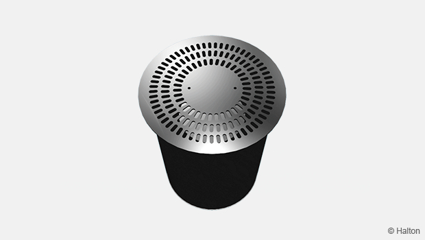
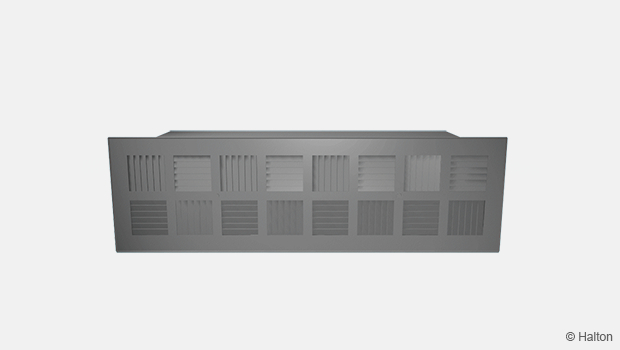
Halton JRF – Floor diffuser
Rectangular diffuser creating comfortable environments for the end user in demanding acoustic spaces.
- Comfortable thermal and good acoustic conditions
- Integrated installation to the floor within the riser of the step
Rectangular diffuser for floor installation
Overview
- Vertical air supply
- Designed for use in auditoriums, theatres, concert halls, classrooms etc.
- Comfortable thermal and good acoustic conditions
- Integrated installation to the floor within the riser of the step
- Ducted or connected to pressurized under-floor plenum chamber
- Pressure drop of the diffuser enables self-balancing in most cases
- Very limited distance between diffuser and seat required
- Detachable front module enables cleaning of the diffuser
Dimensions
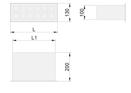
| NS | L | L1 |
| 330×130 | 330 | 300 |
| 430×130 | 430 | 400 |
Material
| Part | Material | Finishing |
| Casing | Galvanised steel | |
| Front panel | Galvanised steel | Epoxy-painted, Black (RAL 9005) |
| Sound attenuation material | Mineral wool |
Function
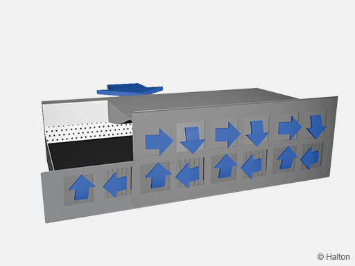
Halton JRF floor diffusers are designed for under-floor air distribution systems.
Air is supplied into the space through the front panel where it mixes efficiently with room air due to the swirl jet air pattern.
The perforated plate inside the casing creates sufficient pressure drop to enable self-balancing system in ductless applications.
The recommended pressure level in the plenum chamber is 30 … 40 Pa.
The recommended supply air temperature is max. 3.5 °C lower than the room temperature.
The supply airflow rate per unit is 14 … 18 l/s.
System Design
Floor supply system design
The Halton JFR floor diffusers are designed for installation within the riser of a step in auditoriums, concert halls, theatres, where a high level of comfort and conveyance is required. Supply air velocity must be very low to reduce discomfort that may be felt in the near zone. We recommend designing as a displacement system with a maximum supply temperature of 3,5 ° C below room. Supply 14 to 18 l/s per unit and allow a distance between outlets of 0.8 to 1 meter. Where comfort requirements are less important, higher airflow rates can be used, generating increased velocities close to the diffuser. Discomfort may be felt if exposed for an extended period of time. In this case outlets should be installed at least 1.5 m from the work place or other continuously occupied areas.
Connection of the diffusers
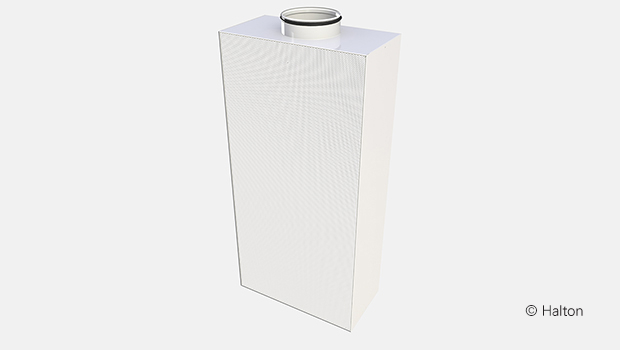
The Halton JRF is suitable for installations without ductwork connections (fig.1).
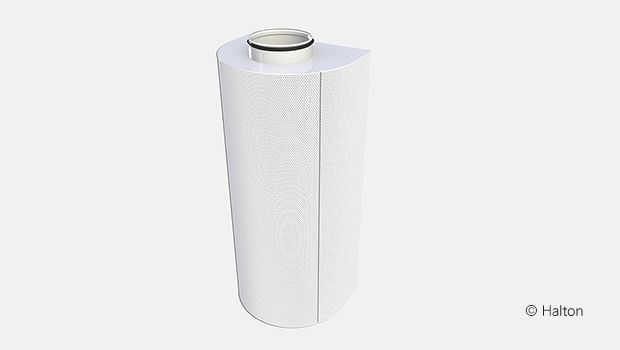
The space beneath the raised floor is used as a distribution plenum chamber. Construction includes an acoustic plenum with perforated cylinder, which causes an efficient pressure loss and provides a self-balancing system.
We recommend designing the system so that the pressure inside the plenum chamber will be 30 … 40 Pa.
Where the plenum chamber has a large volume, we recommend the use of multiple air introduction points.
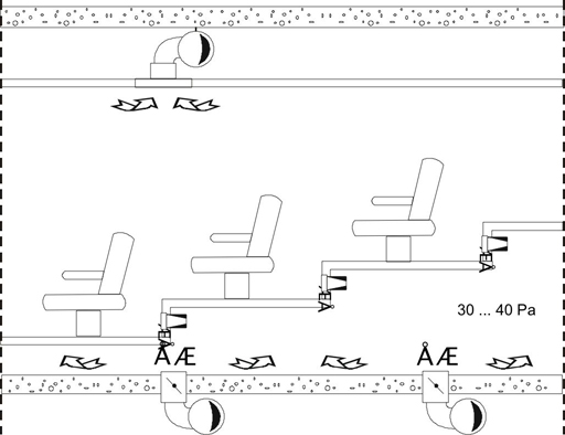
Fig.1
Measurements
Velocity and temperature measurement
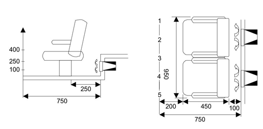
Halton JRF-330×130
Airflow rate qv 14 l/s (50 m³/h)
Supply temperature 21,5 °C
Room temperature 25,0 °C
ΔT – 3,5 °C
| Height mm |
1 | 2 | 3 | 4 | 5 |
| 400 | 0.12 m/s 24.2°C |
0.12 m/s 24.5°C |
0.11 m/s 24.1°C |
0.11 m/s 24.2°C |
0.12 m/s 24.2°C |
| 250 | 0.11 m/s 24.4°C |
0.11 m/s 24.7°C |
0.13 m/s 24.1°C |
0.14 m/s 24.2°C |
0.11 m/s 24.3°C |
| 100 | 0.17 m/s 23.5°C |
0.13 m/s 23.9°C |
0.19 m/s 24.1°C |
0.13 m/s 23.8°C |
0.16 m/s 23.6°C |
Halton JRF-430×130
Airflow rate qv 18 l/s (65 m³/h)
Supply temperature 21,5 °C
Room temperature 25,0 °C
ΔT – 3,5 °C
| Height mm |
1 | 2 | 3 | 4 | 5 |
| 400 | 0.13 m/s 24.2°C |
0.13 m/s 24.3°C |
0.12 m/s 24.5°C |
0.12 m/s 24.3°C |
0.13 m/s 24.8°C |
| 250 | 0.12 m/s 24.3°C |
0.12 m/s 24.6°C |
0.14 m/s 24.1°C |
0.14 m/s 24.4°C |
0.13 m/s 24.3°C |
| 100 | 0.18 m/s 23.0°C |
0.14 m/s 23.3°C |
0.21 m/s 22.9°C |
0.14 m/s 23.5°C |
0.19 m/s 23.2°C |
Installation
The Halton JRF is connected directly onto the floor, by fixing the casing to the floor.
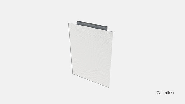
The front panel (supply air part) is fastened with screws.
Adjustment
The airflow rate is adjusted by setting the plenum chamber static pressure to the required pressure level.
Servicing
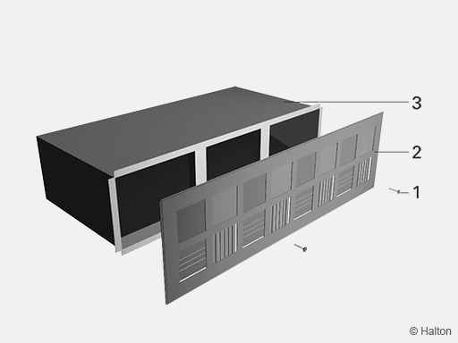
Code description
1. Screws
2. Front panel
3. Casing
Detach the front panel from the casing by unscrewing the screws..
Clean the parts by wiping them with a damp cloth, instead of immersing in water.
Reattach the front panel by screwing it to the casing.
Specification
The casing is made of galvanised steel.
The front panel is made of galvanised steel epoxy-painted to black (RAL 9005) colour.
The perforated plate inside the casing creates sufficient pressure drop to enable self-balancing in applications with a pressurised plenum chamber.
The diffuser has a swirl air jet supply pattern.
Sound attenuation material within the casing is made of mineral wool.
Order code
JRF/S-W-H; CO-ZT
S = Model
N Standard
F Front plate only
W = Width (mm)
330, 430
H = Height (mm)
130
Other options and accessories
CO = Colour
B Black (RAL 9005)
ZT = Tailored product
N No
Y Yes (ETO)
Code example
JRF/N-330-130, CO=B, ZT=N
Downloads
"*" indicates required fields