Product / DRV
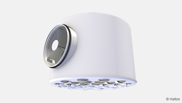
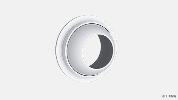
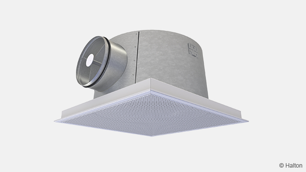
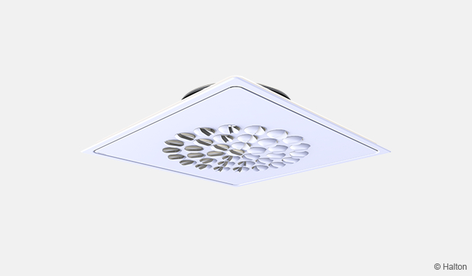
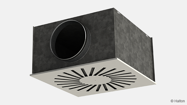
Halton DRV – Multi-nozzle terminal unit
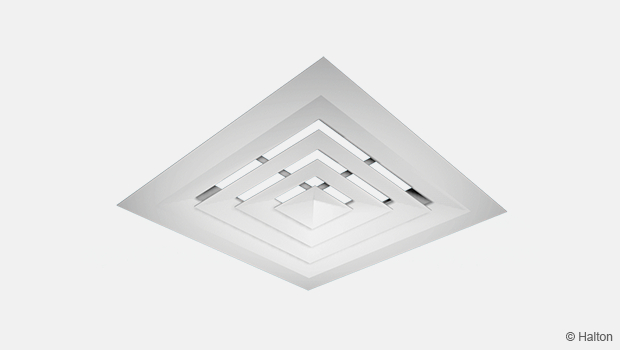
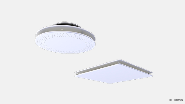
Circular and compact in design for free installation with adjustable airflow.
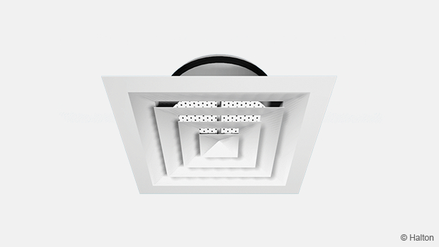
- Directional nozzles with two-slot air paths efficiently deflect the airstreams
- Supply air velocity is efficiently reduced due to the high mixing effect
Overview
- Horisontal or vertical air supply
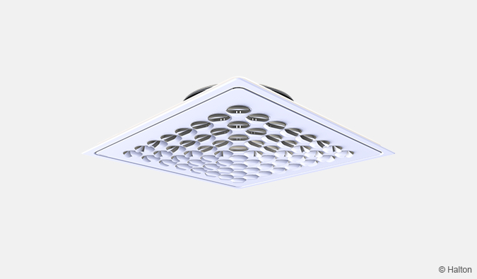
- Directional nozzles with two-slot air path efficiently deflect the airstreams
- Supply air velocity is efficiently reduced due of high mixing effect
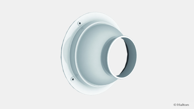
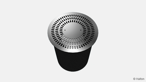
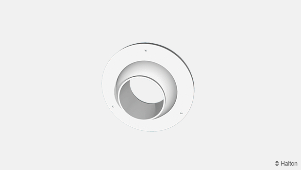
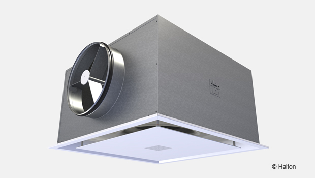
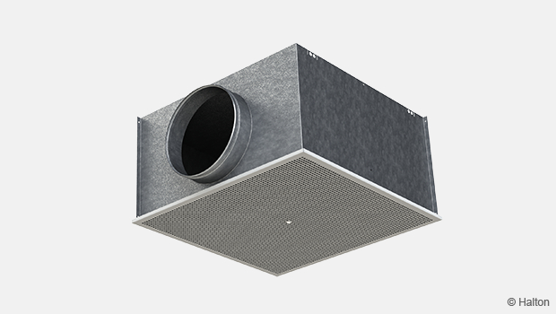
- Integrated circular balancing plenum with measurement and adjustment functions
- Circular duct connection with gasket
- Detachable front panel enables cleaning of the terminal unit and ductwork
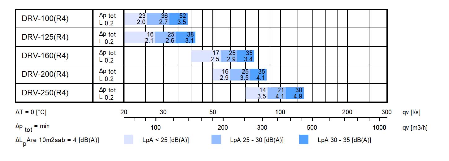
Quick selection
Dimensions
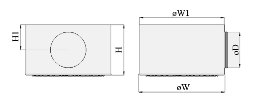
| NS | ØW | ØW1 | H | H1 | ØD |
| 100 | 300 | 289 | 231 | 93 | 99 |
| 125 | 300 | 289 | 231 | 103 | 124 |
| 160 | 450 | 439 | 269 | 121 | 159 |
| 200 | 450 | 439 | 293 | 138 | 199 |
| 250 | 600 | 589 | 351 | 174 | 249 |
Material
| Part | Material | Note |
| Front panel | Steel | – |
| Nozzles | Polypropylene (PP) | Colour alternatives: White, Grey and Black |
| Plenum | Galvanised steel | – |
| Attenuation material | Polyester fibre | – |
| Coupling sleeve | Galvanised steel | – |
| Gasket | Rubber compound | – |
| Finishing | Painted, white (RAL 9003) | Special colours available |
Function
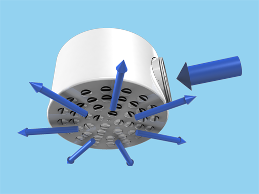
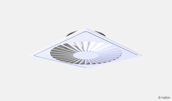
Air is supplied either horizontally into the space or alternatively vertically through the adjustable nozzles in the front panel of the diffuser and mixed with the room air outside of the diffuser. Horizontal swirl jet and different air patterns can also achieved by adjusting the nozzles.
The recommended maximum air temperature difference between supply and room air is 10 0C.
The maximum recommended temperature for plastic material is 60 0C.
Installation
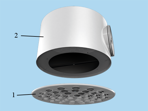
Key
1. Front panel with nozzles
2. Plenum
The terminal unit is connected directly to the duct by screwing or riveting. Adjust the flow pattern in the desired direction by individually rotating each nozzle in order to meet the required specification.
It is recommended that the minimum safety distance before the terminal unit is 3xD.
Adjustment
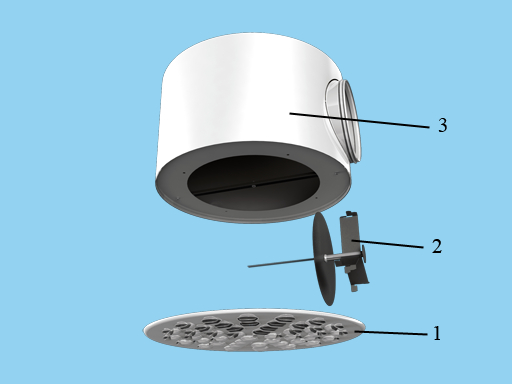
Key
1. Front panel with nozzles
2. Measurement and adjustment module
3. Plenum
The supply airflow is determined using the measurement and adjustment module MSM.
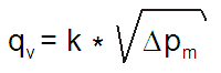
Detach the plug in the plenum and connect the manometer. Measure the differential pressure using the connected manometer. The supply airflow rate is calculated using the formula below.
Adjust the supply airflow rate by rotating the control spindle until the desired setting is achieved.
Lock the damper position with the screw.
Reassemble the tubes and spindle into the plenum and reinstall the plug.
The k factors for installations with different safety distances
(D = duct diameter)
| NS | > 8xD | min. 3xD |
| 100 | 6,0 | 8,5 |
| 125 | 10,0 | 13,0 |
| 160 | 17,1 | 22,8 |
| 200 | 27,5 | 32,1 |
| 250 | 47,9 | 55,5 |
Servicing
Detach the cover plug and open the front panel of the diffuser. By pressing the stoppers each nozzle can easily be removed through the front panel. Wipe the nozzles and front panel with damp cloth. The nozzles are relpaced by pushing into the front panel.
Remove the measurement and adjustment module by gently pulling the shaft (not the control spindle or measurement tubes!). Wipe the parts with damp cloth, instead of immersing in water.
Reassembly the measurement and adjustment module by pushing the shaft back into place until yhe unit meets the stopper.
Reinstall the front panel back into place.
Specification
The diffuser and plenum is made of painted steel with a white (RAL 9003) standard colour. The front panel of the diffuser is equipped with plastic nozzles, which have two-slot construction in order to ensure effective mixing of supply air. Nozzles are individually adjustable to provide high flexibility for the adjustment of the throw pattern.
The diffuser is integrated to a balancing plenum equipped with a measurement and adjustment module.
The diffuser has detachable front panel in order to provide access to the measurement and balancing module in the plenum and to the duct.
The plenum has detachable a spigot equipped with integral gasket for airtight duct connection.
Order code
DRV/D; CO-ZT
D = Diameter of duct Connection
100, 125, 160, 200, 250
Other options and accessories
CO = Colour
SW Signal white RAL 9003
X Special colour (RAL xxxx)
Colour for nozzles is not selectable.
ZT = Tailored product
N No
Y Yes (ETO)
Code example
DRV-100, CO=SW, ZT =N
Downloads
"*" indicates required fields
Halton APL – Jet air diffuser
product
Halton APS – Jet air diffuser
product
Halton BCF – Floor diffuser
product
Halton CAR – Conical diffuser
product
Halton DAC – Square diffuser
product
Halton DCS – Modular diffuser
product
Halton DFA – Square conical diffuser
product
Halton DFB – Conical diffuser
product
Halton DRV – Multi-nozzle terminal unit
product
Halton IAO – Jet nozzle diffuser
product
Halton Jaz JCC – Diffuser
product
Halton Jaz JDA – Diffuser with side slot
product
Halton Jaz JDB – Diffuser with side slot
product
Halton Jaz JDS – Variable air volume diffuser unit (VAV)
product
Halton Jaz JMC – Nozzle diffuser
product
Halton Jaz JRC – Perforated diffuser
product
Halton Jaz JRP – Swirl diffuser
product
Halton Jaz JSC – Nozzle diffuser
product
Halton Jaz JTH – Swirl diffuser
product
Halton Jaz JWC – Swirl diffuser
product