Product / DFB
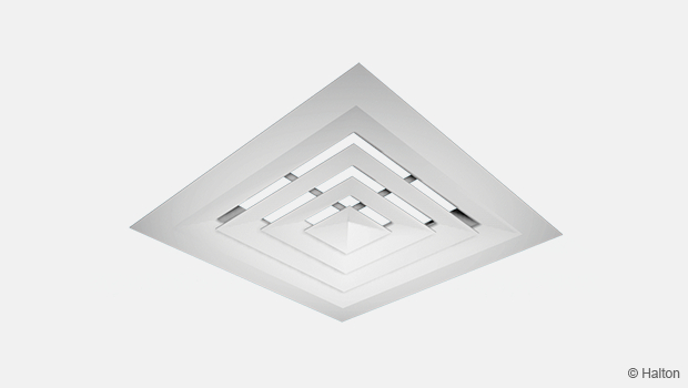
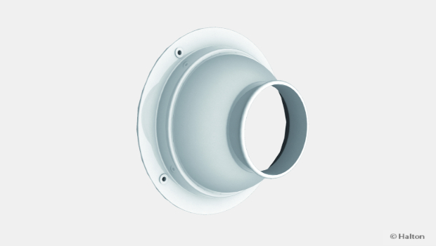
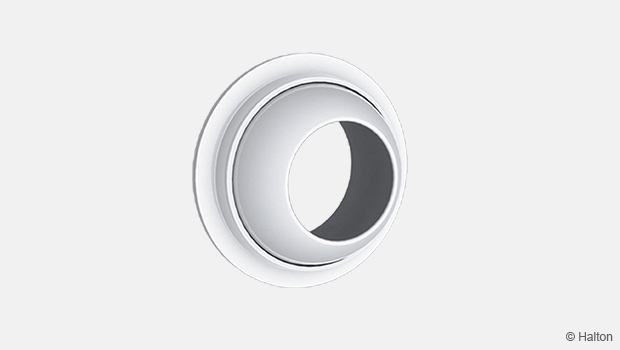
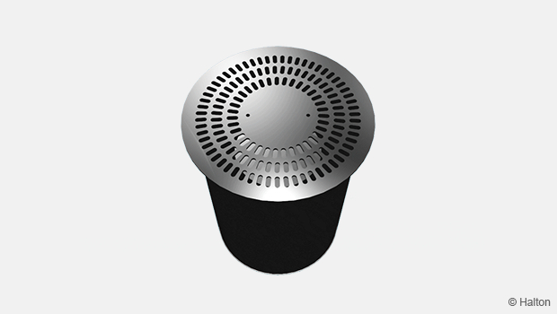
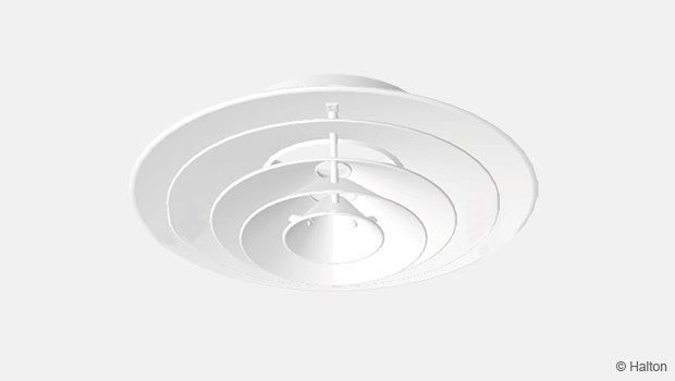
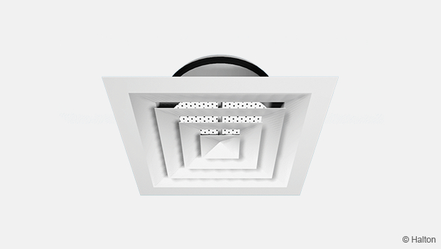
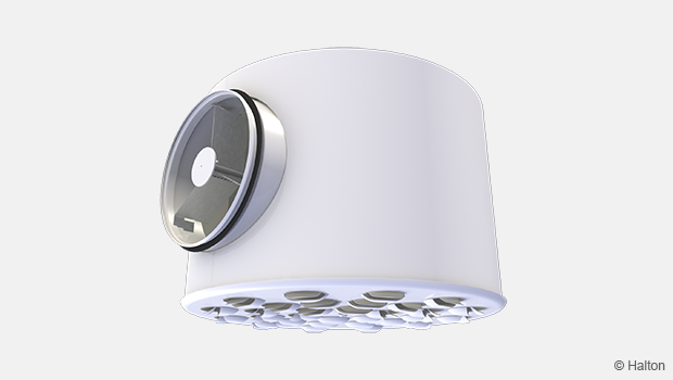
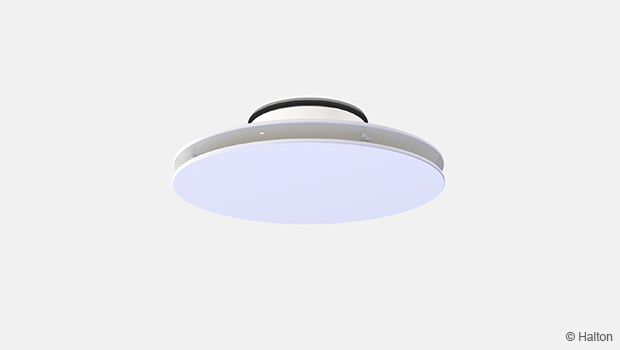
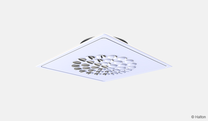
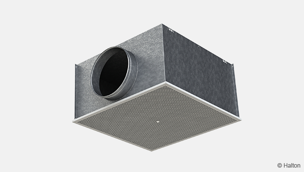
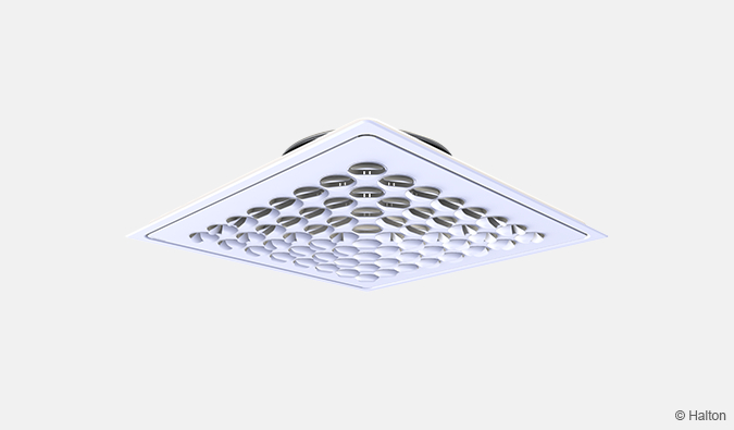
Halton DFB – Conical diffuser
Easy to clean and maintain.
- Suitable for horisontal supply and exhaust
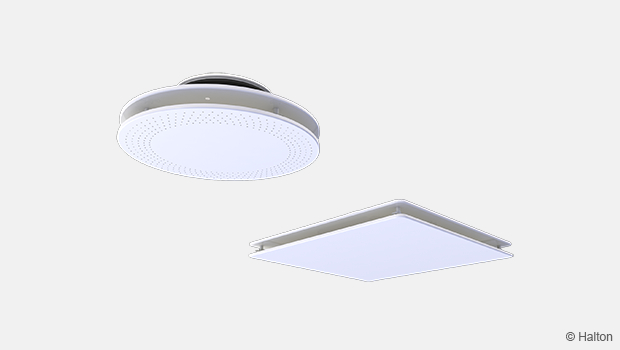
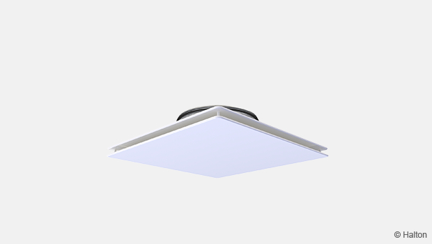
- All sizes adapted for installation in modular 600×600 mm suspended ceiling
Overview
- Suitable for horisontal supply and exhaust
- Openable cone module enables cleaning of the diffuser and ductwork.
- All sizes adapted for installation in modular 600×600 mm suspended ceiling
- Lightweight aluminum material
Accessories
- Airflow adjustment damper
- Plenum options with measurement and adjustment functions
- Measurement and adjustment module
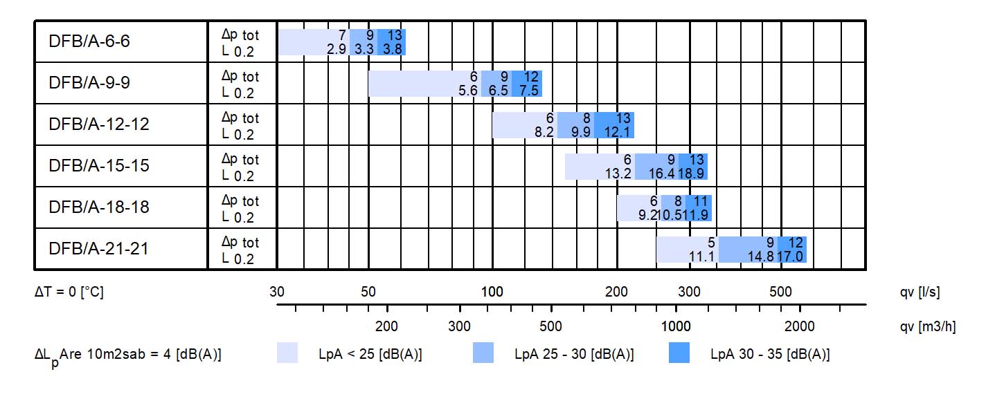
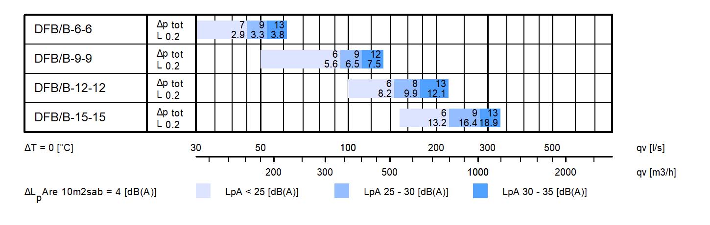
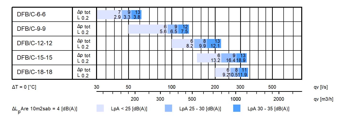
Quick selection
Dimensions
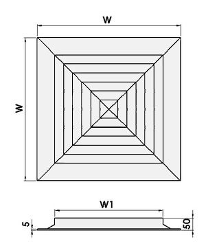
| NS | W | W1 |
| 6×6 | 295 | 150 |
| 9×9 | 370 | 225 |
| 12×12 | 445 | 300 |
| 15×15 | 520 | 375 |
| 18×18 | 595 | 450 |
| 21×21 | 670 | 525 |
| 24×24 | 745 | 600 |
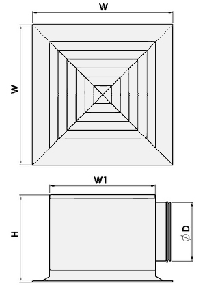
| NS | W | W1 | H | ØD |
| 6×6 | 295 | 150 | 225 | 124 |
| 9×9 | 370 | 225 | 310 | 199 |
| 12×12 | 445 | 300 | 350 | 249 |
| 15×15 | 520 | 375 | 415 | 314 |
| 18×18 | 595 | 450 | 500 | 399 |
| 21×21 | 670 | 525 | 550 | 449 |
| 24×24 | 745 | 600 | 600 | 499 |
Material
| Part | Material | Finishing | Note |
| Frame | Aluminium | Polyester-painted, White (RAL 9003 / 30% gloss) |
Special colours available |
| Central cone | Aluminium | Polyester-painted, White (RAL 9003 / 30% gloss) |
Special colours available |
Accessories
| Accessory | Code | Description |
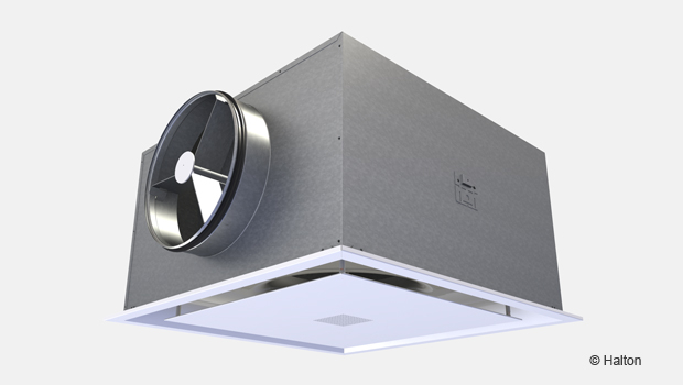
| Plenum | PDF/H | Plenum for horizontal duct connection (with or without insulation) |
| Plenum | PDF/V | Plenum for vertical duct connection (with or without insulation) |
| Airflow measurement and adjustment module |
MSM | For supply installation |
| Sound attenuation | IN | Mineral wool in the plenum |
| Flow adjustment damper | ODD | Aluminium opposite blade damper for flow adjustment |
Product Models
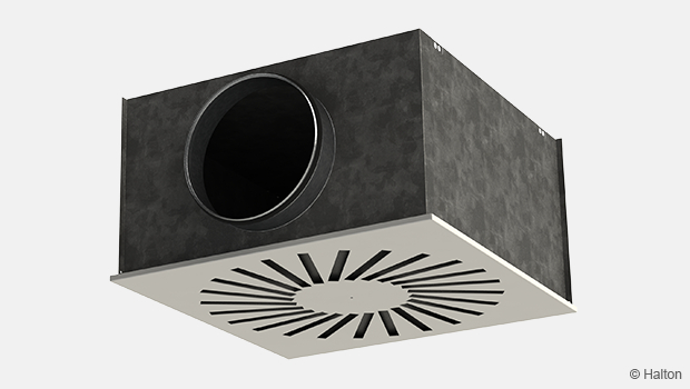
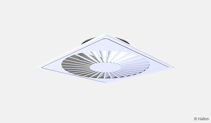
All standard sizes are available also with 1, 2 or 3 supply directions (DFC).
Function
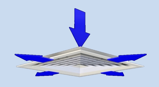
Air is supplied horisontally into the space through the slots in the conical front panel.
Supply air mixes with room air in the vicinity of the diffuser.
The fixed cones of the diffuser are designed to ensure that the supply air flows along the ceiling.
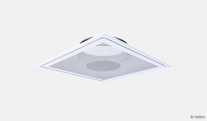
The Halton DFB diffuser can also be used as an exhaust unit.
Installation
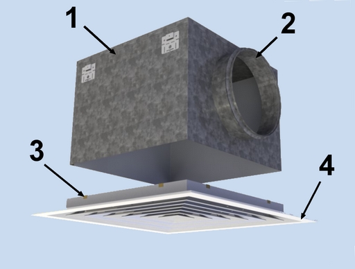
Code description
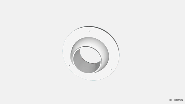
1. Plenum
2. Spigot
3. Clips
4. DFB or DFC plenum
Plenum installation
The plenum is installed into the suspended ceiling with M8 drop rods (not supplied in the delivery) and connected to the ductwork with a spigot.
When equipped with a measurement and adjustment module, the recommended safety distance upstream of the device is at least 3xD, in order to ensure a reliable airflow rate measurement.
The units control spindle must not be excessively bent.
Diffuser installation
The diffuser is attached to the plenum via clips.
Dimensions of installation hole
| NS | H (mm) | L (mm) |
| 6×6 | 215 | 215 |
| 9×9 | 290 | 290 |
| 12×12 | 365 | 365 |
| 15×15 | 440 | 440 |
| 18×18 | 515 | 515 |
| 21×21 | 590 | 590 |
| 24×24 | 665 | 665 |
Adjustment
To aid in adjusting and measuring the air flow rate, it is recommended that the diffuser is connected to a plenum equipped with a MSM.
The supply airflow is determined by measuring the pressure difference with a measurement module.
Measure the differential pressure with a manometer.
The airflow rate is calculated according to the following formula:
where:
∆Pm is the measured pressure (Pa)
k is a factor given as a function of mounting and diameter
Qv is the airflow rate
The k factor for installations with different safety distances (distance of other items from the MSM):
| Safety distance | ||
| Spigot Diameter | > 6xD | min. 3xD |
| 100 | 6 | 7 |
| 125 | 10 | 12 |
| 160 | 19 | 22 |
| 200 | 28 | 32 |
| 250 | 49 | 51 |
| 315 | 78 | – |
Airflow adjustment damper OD
The airflow rate is adjusted by turning the damper blades behind the grille with a screwdriver. The measurement is carried out when diffuser is installed.
Servicing
Remove the central cones by gently drawing out the central part.
Clean the parts by wiping them with a damp cloth.
Push the central cones back into place so that the springs lock.
Option: With balancing plenum Halton PDF + MSM
Remove the measurement and adjustment module by gently pulling the shaft (not the control spindle).
Wipe the parts with a damp cloth, instead of immersing in water.
Remount the measurement and adjustment module by pushing in the shaft until the module meets the stopper.
Push the central cones back into place so that the springs lock.
Specification
The diffuser is made of extruded aluminium, polyester-painted to white (RAL 9003) colour.
The bevel angles of the outer frame and central cone are welded so that the joints are almost invisible.
The diffuser is connected to the ductwork using a plenum with mineral wool as sound attenuation material.
The plenum is equipped with an airflow measurement and adjustment module.
The central cones of the diffuser sre detachable to provide access to the measurement and adjustment module in the plenum.
Order Code
DFB/S-A-B; FI-CO-ZT
S = Model
A Standard
B Suspended ceiling installation 600×600
C Suspended ceiling installation 675×675
A = Size of connection
S=A: 6, 9, 12, 15, 18, 21, 24
S=B: 6, 9, 12, 15
S=C: 6, 9, 12, 15, 18
B = Height of connection
A=6: 6
A=9: 9
A=12: 12
A=15: 15
A=18: 18
A=21: 21
A=24: 24
Other options and Accessories
FI = Finishing
PN Painted
CO = Colour
SW White (RAL 9003)
X Special colour
ZT = Tailored product
N No
Y Yes (ETO)
Sub products
PDF Plenum for DFB and DFC
Code example
DFB/A-6-6, FI=PN, CO=SW, ZT=N
Downloads
"*" indicates required fields
Halton APL – Jet air diffuser
product
Halton APS – Jet air diffuser
product
Halton BCF – Floor diffuser
product
Halton CAR – Conical diffuser
product
Halton DAC – Square diffuser
product
Halton DCS – Modular diffuser
product
Halton DFA – Square conical diffuser
product
Halton DFB – Conical diffuser
product
Halton DRV – Multi-nozzle terminal unit
product
Halton IAO – Jet nozzle diffuser
product
Halton Jaz JCC – Diffuser
product
Halton Jaz JDA – Diffuser with side slot
product
Halton Jaz JDB – Diffuser with side slot
product
Halton Jaz JDS – Variable air volume diffuser unit (VAV)
product
Halton Jaz JMC – Nozzle diffuser
product
Halton Jaz JRC – Perforated diffuser
product
Halton Jaz JRP – Swirl diffuser
product
Halton Jaz JSC – Nozzle diffuser
product
Halton Jaz JTH – Swirl diffuser
product
Halton Jaz JWC – Swirl diffuser
product