Product / DCS
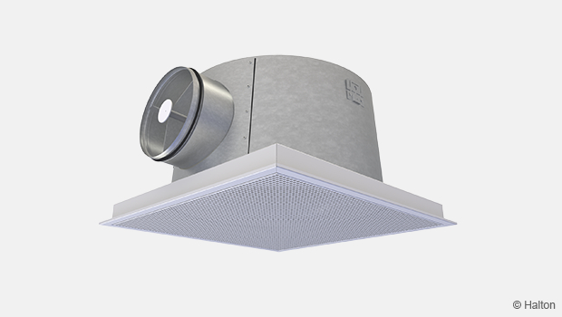
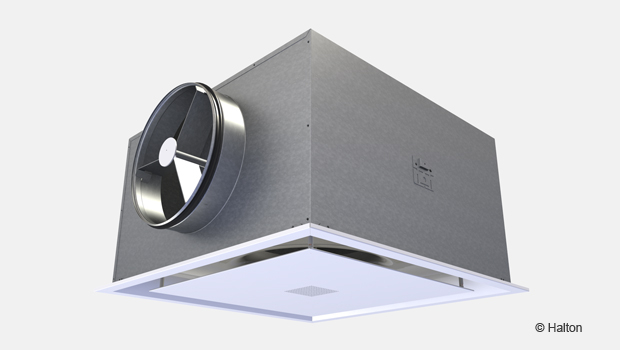
Halton DCS – Modular diffuser
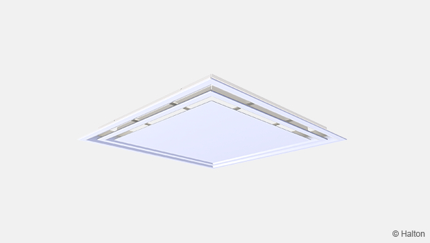
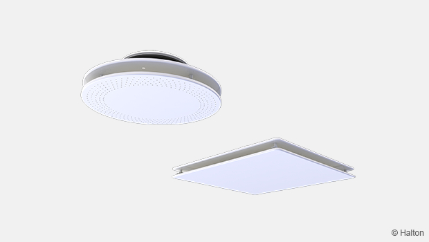
Multi-functional and easy to clean ceiling diffuser with different front panel options, packet with plenum.
- Modular construction with five different, interchangeable front panel options suited for modular 600 x 600, 625×625, 675×675 mm ceilings, providing different appearance and performance characteristic
- Diffuser adaptation possibility for changing ventilation rate requirements
Overview
- Available for supply and exhaust
- Modular construction with five different, interchangeable front panel options suited for modular 600 x 600, 625 × 625, 675 × 675 mm ceilings, providing different appearance and performance characteristic
- Diffuser adaptation possibility for changing ventilation rate requirements
- Detachable front panel enabling the cleaning of the diffuser and ductwork
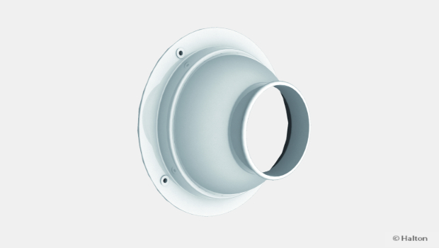
- Connection to ductwork using integrated balancing plenum with optional duct connection dimensions and plenum heights
- Circular duct connection with integral gasket
- Balancing plenum with an air flow rate measurement function
Accessories
- Airflow range adapter
- Various front panel options
- Deflectors for the direction of the flow pattern for models DCS/C and DCS/P
- Sound attenuation options
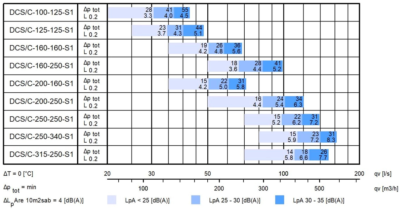
Quick selection
Dimensions
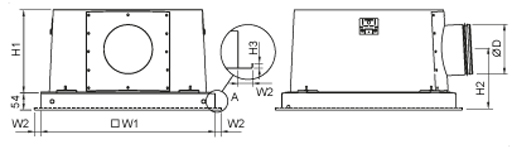
| NS | H1 | H2 | W1 | Ø D |
| 100 | 163 | 135 | 555 | 99 |
| 125 | 163 | 135 | 555 | 124 |
| 160 | 263 | 189 | 555 | 159 |
| 200 | 263 | 189 | 555 | 199 |
| 250 | 363 | 239 | 555 | 249 |
| 315 | 363 | 239 | 555 | 314 |
| Ceiling integrations | H3 | W2 |
| T-ceiling 600 | 6 | 20.5 |
| T-ceiling 625 | 6 | 33 |
| T-ceiling 675 | 6 | 58 |
| Plaster-Armstrong 600 | 6 | 20,5 |
| Dampa 600 | 20 | 22 |
| Fineline 600 | 8 | 15 |
| Fineline 675 | 8 | 52,5 |
Material
| Part | Material | Note |
| Perforated front panel | Perforated steel | |
| Conical front panel | Aluminium | |
| Swirl diffuser front panel |
Steel | |
| Multi-nozzle front panel |
Steel | |
| Nozzles | Plastic | The maximum recommended temperature for plastic nozzle material is 60°C. Nozzle colour options: white and black |
| Balancing plenum | Galvanised steel | |
| Sound attenuation material |
Polyester fiber Mineral wool |
2 options |
| Spigot | Galvanised steel | |
| Coupling sleeve with gasket |
Hot galvanised steel | Rubber compound gasket |
| Adjustment module MSC,MEC |
Body: Aluminium Blade: Galvanised steel Brackets: Galvanised steel Plastic parts: Polypropylene (PP) Spindle: Stainless steel |
|
| Airflow equalizer | Steel Plastic parts: Polypropylene (PP) |
|
| Ceiling adapter | Steel | |
| Finishing of perforated front panel (DCS/P) |
Epoxy painted: White (RAL 9003 / 30 % gloss) |
Special colours available |
| Finishing of conical front panels (DCS/C, DCS/A) |
Polyester painted: White (RAL 9003 / 30 % gloss) |
Epoxy painting (100 %) available |
| Finishing of multi-nozzle front panel (DCS/N) |
Epoxy painted:White (RAL 9003 / 30 % gloss) |
Special colours available |
| Finishing of swirl jet front panel (DCS/J) |
Epoxy painted: White (RAL 9003 / 30 % gloss) |
Special colours available |
Accessories
| Accessory | Code | Description | Note |
| Duct connection with spigot | SP/DCS | Interchangeable duct size | |
| Air flow range adapter | N/DCS | Adaptation of air flow range | |
| Sound attenuation | AT/DCS | Sound absorption material for duct noise attenuation |
Material options: Polyester fiber Mineral wool |
| Perforated front panel, conical front panel, conical solid centre front panel, multi-nozzle front panel, swirl diffuser front panel |
P/DCS, C/DCS, A/DCS, N/DCS, J/DCS |
Exchangeable front panels |
Function
The diffuser allows both appearance and performance to be changed and adapted to new requirements and operation conditions.
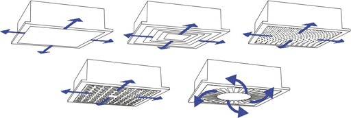
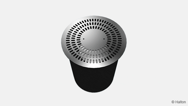
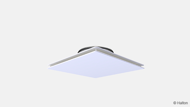
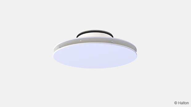
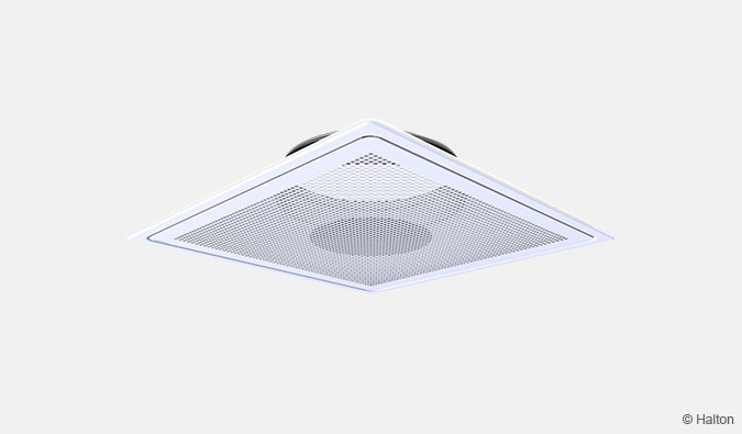
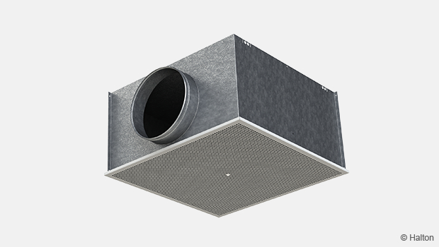
Halton DCS/P
Air is supplied to the space through the perforated front panel and mixed into the room air outside the diffuser. The recommended maximum air temperature difference between supply and room air is -8 °C.
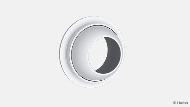
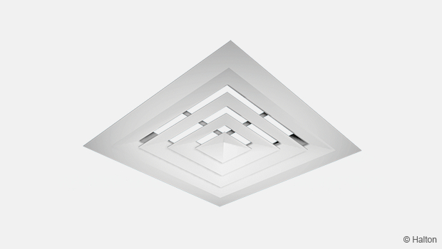
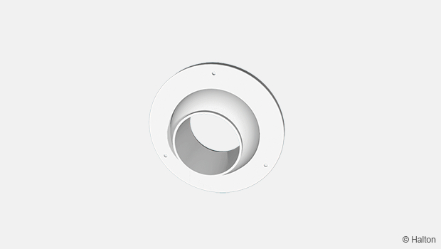
Halton DCS/C
Air is supplied to the space through the slots of the conical front panel and mixed into the room air outside the diffuser. The recommended maximum air temperature difference between supply and room air is -12 °C.
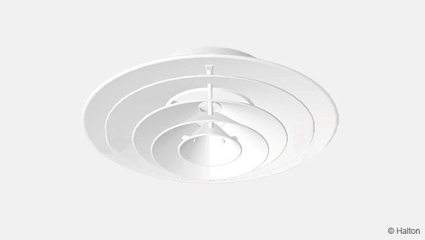
Halton DCS/A
Air is supplied to the space through the slots of the conical front panel and mixed into the room air outside the diffuser. The recommended maximum air temperature difference between supply and room air is -12 °C.
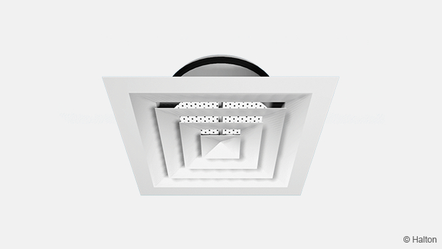
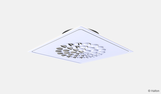
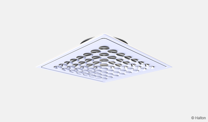
Halton DCS/N
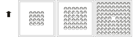
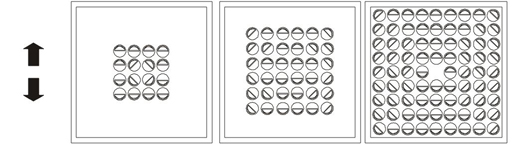
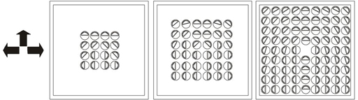
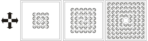
Air is supplied both horisontally and vertically to the space through the front panel of the diffuser.
The supply air pattern can be radially directed in the direction(s) desired (1, 2, 3, and 4) by manually rotating the nozzles.
Horisontal swirl jet and later vertical air patterns can also be achieved by adjusting the nozzles.
The direction of the supply air has no effect on the pressure drop or the air flow rate.
The recommended maximum air temperature difference between supply and room air is -10 °C
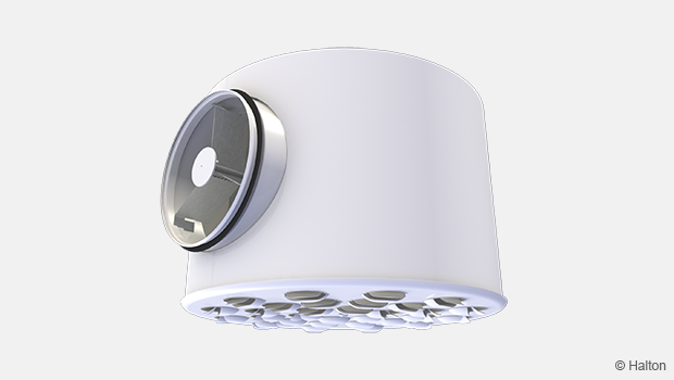
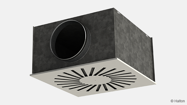
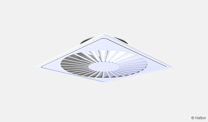
Halton DCS/J
The horizontal radial swirl jet air is supplied to the space through the profiled spiral blades of the diffuser The recommended maximum air temperature difference between supply and room air is -12 °C.
The supply air jet velocity is effectively reduced because of the high mixing effect.
Function in general
The balancing plenum equalises the air flow by reducing the flow velocity.
Air is spread evenly into the diffuser, ensuring proper function.
Air flow range can be adapted to the actual demand by changing the air flow range adapter, by which means proper air distribution for a wide operation range is ensured. (DCS/P, DCS/C, DCS/A, DCS/J)
The airflow rate can be adjusted by using the detachable measurement and adjustment module.
The balancing plenum also attenuates duct noise.
The diffuser can also be used as an exhaust unit.
Nozzle Settings
Installation
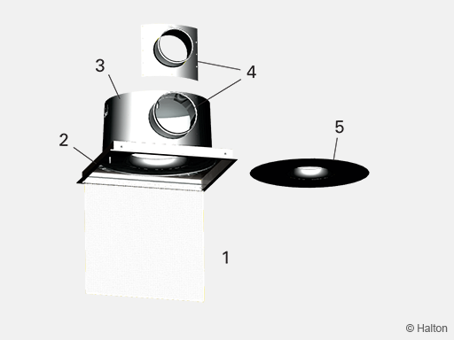
Code description
1. Front panel
2. Ceiling adapter
3. Balancing plenum
4. Duct connection with spigot
5. Air flow range adapter
As needed, the duct connection size and air flow range adapter can be changed in order to adapt the installed diffuser to a significantly reduced or increased air flow rate.
Multi-nozzle diffusers do not have air flow range adapters. Instead, front panels with more or fewer nozzles are changed in this context in the stead of an air flow range adapter change.
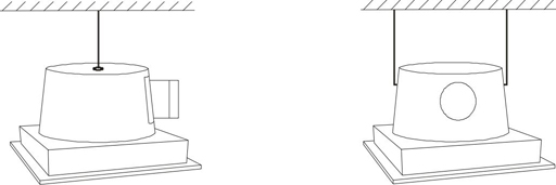
The diffuser is connected to the balancing plenum via fastening plates and screws.
Adjustment
The supply and the exhaust flow rates are determined by measuring the differential pressure from the measurement nipple with a manometer.
The air flow rate is calculated by using the formula below.
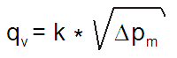
The k-values for exhaust
| Neck | DCS/A | DCS/C | DCS/J | DCS/P |
| 340 | 32.3 | 69.6 | 28.9 | 79.3 |
| 250 | 27.9 | 47.2 | 21.2 | 51.8 |
| 160 | 17.6 | 21.4 | 13.6 | 23.2 |
| 125 | 9.7 | 11.1 | 8 | 12 |
| Nozzles | DCS/N |
| 80 | 52.8 |
| 36 | 27.2 |
| 16 | 12.9 |
The k-values for supply
Halton DCS/A
| Neck | k-value | k-value 0-opening |
| 340 | 33.1 | 27.7 |
| 250 | 26.6 | 0.07 x D + 2.82 |
| 160 | 13.8 | 11.3 |
| 125 | 8.2 | 6.6 |
Halton DCS/C
| Neck | Directioning | k-value | k-value 0-opening |
| 340 | R4 | 52.9 | 0.24 x D – 31.75 |
| 340 | R3 | 49.7 | 0.24 x D – 31.75 |
| 340 | R2 | 44 | 0.24 x D – 31.75 |
| 250 | R4 | 32 | 0.08 x D + 2.73 |
| 250 | R3 | 32.6 | 0.08 x D + 2.73 |
| 250 | R2 | 29.2 | 0.08 x D + 2.73 |
| 160 | 14.5 | 11.4 | |
| 125 | 8.3 | 6.6 |
Halton DCS/J
| Neck | k-value | k-value 0-opening |
| 340 | 33.1 | 26.3 |
| 250 | 26.1 | 0.06xD+4.31 |
| 160 | 14.1 | 11.4 |
| 125 | 8.4 | 6.6 |
Halton DCS/N
| Nozzles | Duct connection | k-value | k-value 0-opening |
| 80 | 315, 250 | 48.1 | 0.18 x D – 13.12 |
| 80 | 200 | 40.5 | 0.18 x D – 13.12 |
| 36 | 27.4 | 0.08 x D + 2.37 | |
| 16 | 13.2 | 0.06 x D + 1.00 |
Halton DCS/P
| Neck | Directioning | k-value | k-value 0-opening |
| 340 | R4 | 50.6 | 0.22 x D – 26.91 |
| 340 | R3 | 47.7 | 0.22 x D – 26.91 |
| 340 | R2 | 46.3 | 0.22 x D – 26.91 |
| 250 | R4 | 30.3 | 0.08 x D + 3.94 |
| 250 | R3 | 29.6 | 0.08 x D + 3.94 |
| 250 | R2 | 28.6 | 0.08 x D + 3.94 |
| 160 | 13.4 | 11.1 | |
| 125 | 8 | 6.3 |
Obs.
D = diameter of duct connection in mm
Adjust the air flow rate by rotating the control spindle of the MSC/MEC unit until the desired setting is achieved.
Lock the damper in position with a screw. Replace the spindle in the plenum.
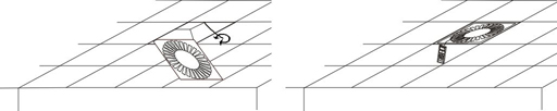
Servicing
Open the front panel of the diffuser.
Detach the air flow range adapter by unscrewing the four screws.
Remove the air flow adjustment module by pulling gently on the shaft (not the control spindle).
Wipe the parts with a damp cloth, instead of immersing in water.
The washable Dacron sound attenuation material within the plenum can be removed to enable cleaning of the inner side of the plenum.
Remount the measurement and adjustment module by pushing on the shaft until the unit meets the stop.
Fix the air flow range adapter in place by screwing in the four screws.
Push the front panel back into its place so that the springs lock.
Specification
The diffuser is of the modular type and comprise a diffuser and balancing plenum.
The front panel dimensions is adapted to a modular 600 x 600 mm suspended ceiling.
The front panel of the diffuser is changeable, providing different appearance options.
The airflow operating range is adaptable by replacing an exchangeable airflow range adapter, independently of the diffuser size
(DCS/P, DCS/C, DCS/A, DCS/J).
The duct connection has optional dimensions, for adaptation to different airflow rates.
The balancing plenum is made of galvanised steel, comprising a changeable spigot in different sizes with integral gasket for airtight duct connection.
The front panel of the diffuser is detachable for access to the balancing plenum, the airflow range adapter, ductwork and the airflow measurement and adjustment module.
DCS/P
The perforated front panel of the diffuser is made of epoxy-painted steel with white (RAL 9003) as the standard colour.
DCS/C DCS/A
The conical front panel of the diffuser is made of extruded aluminium, with polyester white (RAL 9003) as standard colour.
DCS/J
The swirl front panel of the diffuser is made of epoxy-painted steel with a white (RAL 9003) standard colour. The swirl diffuser comprises fixed spiral blades to ensure a high mixing rate.
DCS/N
The multi-nozzle front panel of the diffuser is made of epoxy-painted steel with a white (RAL 9003) standard colour. The nozzles have a two-slot design in order to ensure efficient mixing of supply air. Nozzles also are individually adjustable in order to provide high flexibility for the adjustment of the throw pattern.
Order code
DCS/F-D-N-M; J-IO-AT-CO-ZT
F = Front panel
C Conical
A1 Conical with centre plate, 1
A2 Conical with centre plate, 2
A3 Conical with centre plate, 3
P Perforated
J Swirl
N1 Nozzle, 16 pcs
N2 Nozzle, 36 pieces
N3 Nozzle, 80 pieces
D = Diameter of duct connection
100, 125, 160, 200, 250, 315
N = Air flow range adapter
125, 160, 250, 340
N None, if F = N1, N2 or N3
M = Model
S1 Supply + MSC
S2 Supply +Airflow equaliser
E1 Exhaust + MEC
E2 Exhaust + Airflow equaliser
Other options and accessories
J = Jet direction
R2 2 directions
R3 3 directions
R4 4 directions
IO = Ceiling type installation option
NA Standard for T-profile 600
AM Armstrong Orcal ceiling
DC Dampa ceiling
FL Fineline ceiling 600
TP T-profile 625
T2 T-profile 675
F2 Fineline ceiling 675
AT = Sound attenuation material
N No attenuation material
D Polyester fiber
W Mineral wool
CO = Colour
SW White, RAL 9003
X Special colour
ZT = Tailored product
N No
Y Yes (ETO)
Code example
DCS/C-315-250-S1, J=R3, IO=NA, AT=D, CO=SW, ZT=N
Downloads
"*" indicates required fields
Halton APL – Jet air diffuser
product
Halton APS – Jet air diffuser
product
Halton BCF – Floor diffuser
product
Halton CAR – Conical diffuser
product
Halton DAC – Square diffuser
product
Halton DCS – Modular diffuser
product
Halton DFA – Square conical diffuser
product
Halton DFB – Conical diffuser
product
Halton DRV – Multi-nozzle terminal unit
product
Halton IAO – Jet nozzle diffuser
product
Halton Jaz JCC – Diffuser
product
Halton Jaz JDA – Diffuser with side slot
product
Halton Jaz JDB – Diffuser with side slot
product
Halton Jaz JDS – Variable air volume diffuser unit (VAV)
product
Halton Jaz JMC – Nozzle diffuser
product
Halton Jaz JRC – Perforated diffuser
product
Halton Jaz JRP – Swirl diffuser
product
Halton Jaz JSC – Nozzle diffuser
product
Halton Jaz JTH – Swirl diffuser
product
Halton Jaz JWC – Swirl diffuser
product